EP2046505B1 - Verfahren zur reinigung einer spritzpistole - Google Patents
Verfahren zur reinigung einer spritzpistole Download PDFInfo
- Publication number
- EP2046505B1 EP2046505B1 EP07748209.9A EP07748209A EP2046505B1 EP 2046505 B1 EP2046505 B1 EP 2046505B1 EP 07748209 A EP07748209 A EP 07748209A EP 2046505 B1 EP2046505 B1 EP 2046505B1
- Authority
- EP
- European Patent Office
- Prior art keywords
- cleaning
- spray gun
- paint
- nozzle
- media
- Prior art date
- Legal status (The legal status is an assumption and is not a legal conclusion. Google has not performed a legal analysis and makes no representation as to the accuracy of the status listed.)
- Active
Links
Images


Classifications
-
- B—PERFORMING OPERATIONS; TRANSPORTING
- B05—SPRAYING OR ATOMISING IN GENERAL; APPLYING FLUENT MATERIALS TO SURFACES, IN GENERAL
- B05B—SPRAYING APPARATUS; ATOMISING APPARATUS; NOZZLES
- B05B15/00—Details of spraying plant or spraying apparatus not otherwise provided for; Accessories
- B05B15/50—Arrangements for cleaning; Arrangements for preventing deposits, drying-out or blockage; Arrangements for detecting improper discharge caused by the presence of foreign matter
- B05B15/55—Arrangements for cleaning; Arrangements for preventing deposits, drying-out or blockage; Arrangements for detecting improper discharge caused by the presence of foreign matter using cleaning fluids
- B05B15/555—Arrangements for cleaning; Arrangements for preventing deposits, drying-out or blockage; Arrangements for detecting improper discharge caused by the presence of foreign matter using cleaning fluids discharged by cleaning nozzles
-
- B—PERFORMING OPERATIONS; TRANSPORTING
- B05—SPRAYING OR ATOMISING IN GENERAL; APPLYING FLUENT MATERIALS TO SURFACES, IN GENERAL
- B05B—SPRAYING APPARATUS; ATOMISING APPARATUS; NOZZLES
- B05B15/00—Details of spraying plant or spraying apparatus not otherwise provided for; Accessories
- B05B15/50—Arrangements for cleaning; Arrangements for preventing deposits, drying-out or blockage; Arrangements for detecting improper discharge caused by the presence of foreign matter
- B05B15/55—Arrangements for cleaning; Arrangements for preventing deposits, drying-out or blockage; Arrangements for detecting improper discharge caused by the presence of foreign matter using cleaning fluids
-
- B—PERFORMING OPERATIONS; TRANSPORTING
- B05—SPRAYING OR ATOMISING IN GENERAL; APPLYING FLUENT MATERIALS TO SURFACES, IN GENERAL
- B05B—SPRAYING APPARATUS; ATOMISING APPARATUS; NOZZLES
- B05B7/00—Spraying apparatus for discharge of liquids or other fluent materials from two or more sources, e.g. of liquid and air, of powder and gas
- B05B7/24—Spraying apparatus for discharge of liquids or other fluent materials from two or more sources, e.g. of liquid and air, of powder and gas with means, e.g. a container, for supplying liquid or other fluent material to a discharge device
- B05B7/2402—Apparatus to be carried on or by a person, e.g. by hand; Apparatus comprising containers fixed to the discharge device
- B05B7/2405—Apparatus to be carried on or by a person, e.g. by hand; Apparatus comprising containers fixed to the discharge device using an atomising fluid as carrying fluid for feeding, e.g. by suction or pressure, a carried liquid from the container to the nozzle
Definitions
- the present invention relates to a method for cleaning a spray gun, and more specifically for cleaning a spray gun after use inside a paint spray booth or within a preparatory area.
- the element comprises a container in which the spray gun is inserted for cleaning.
- the element further comprises a suction system and which system inside the container has an intake for gases and vapors.
- Solvent vapors from cleaning of the spray gun are, during cleaning, sucked into the intake and transported to a suitable storage system.
- the spray gun is cleaned by a cleaning media, e.g. a detergent, which cleaning media is applied externally on the spray gun.
- the spray gun further comprises an internal paint distributing passage. This passage is cleaned by a cleaning media which passes through the passage.
- the cleaning media is introduced inside the passage by changing content in a paint cup from paint to a cleaning media, which paint cup then is connected to the spray gun.
- the cleaning media is then introduced into the spray gun with same known technique as used for paint during use of the spray gun.
- a cleaning device for cleaning a paint brush.
- the device comprises a nozzle that is equipped with a valve.
- the valve is in an open position when a brush is moved towards the nozzle.
- a cleaning solution e.g. a detergent, exits the nozzle under pressure when the valve is open.
- the heel or bristles of the brush are engaged against the nozzle whereby the valve opens.
- a flow of the detergent from the nozzle then cleans the brush.
- the paint spray booth is a room comprising a ceiling and walls and wherein a worker can spray an object, e.g. a car or e.g. a part of a car.
- the spray booth is an enclosed area. At least one wall is provided with the possibility to be partly open whereby an object can be placed inside the paint spray booth.
- a spray gun is used by the worker inside the spray booth to paint the placed object.
- the spray booth is equipped with an air providing system. The air providing system provides pressurized air to the spray gun.
- An object of the present invention is to provide a process according to claim 1 whereby a spray gun, which is used for painting in a paint spray booth, after use of one color is cleaned while a worker is holding the spray gun in his or her hand.
- a further object of the present invention is to provide a process whereby a paint distributing passage inside the spray gun is cleaned after use of the spray gun.
- An advantage afforded by a process according to the present invention is that the worker does not have to leave the paint spray booth in order to clean the spray gun.
- a further advantage afforded by a process according to the present invention is that the spray gun is held by hand during the process of cleaning. As such, the worker does not have to leave the spray gun in a conventional cleaning unit for spray guns. Total time for cleaning the spray gun after use is therefore reduced. A further result is that necessary time needed for changing between two different colors is also reduced.
- An example of an embodiment of the process according to the invention includes a second paint cup comprising a second paint located in or within a direct vicinity to the paint spray booth, wherein when painting of the paint contained in a first paint cup is performed.
- the first paint cup is changed to the second paint cup comprising the second paint, wherein the spray gun between the change of the first and the second paint cups is cleaned. Due to achieved results of the cleaning process it is possible to keep paint and to perform change between paints in or within a direct vicinity to the paint spray booth.
- Another example of an embodiment of the process according to the invention includes a disposable paint cup.
- An advantage of using a disposable paint cup is that a step for cleaning the lid and paint cup is removed. When a worker is finished painting with a paint contained in a disposable paint cup, the cup is removed and taken care of in an environmentally correct way. This saves time for the worker as the worker only has to clean the spray gun and not the cup and lid.
- Another example of an embodiment of the process according to the invention includes the cleaning unit being activated by the spray gun. After a worker has finished painting an object, the worker moves the spray gun towards the cleaning unit. As the spray gun is brought into contact with the cleaning unit the cleaning process starts. During this process the spray gun is held by the worker's hand. The cleaning process takes place inside the spray booth where the object to be painted is located or within a direct vicinity to the spray booth. The worker does not have to move away from the spray booth, nor disconnect the spray gun from pressurized air.
- the advantage of this is that the worker can rapidly clean the spray gun as the worker is holding the spray gun and after cleaning change to a new color and then continue painting using the same spray gun.
- Another example of an embodiment of the process according to the invention includes activating the cleaning process by moving the spray gun towards a cleaning nozzle on the cleaning unit.
- the nozzle is provided with a valve which can open and close. Techniques for opening and closing the valve are known to a person skilled in the art.
- the advantage of having the spray gun activating the cleaning process is that it reduces the number of necessary steps for cleaning the spray gun compared to traditional spray gun cleaning processes.
- Another example of an embodiment of the process according to the invention comprises the cleaning unit having a pedal, which pedal when pressed activates the cleaning process.
- the pedal is located in an area where a worker's feet are located.
- An advantage of this is that the pedal is close to the floor or ground and it does not take space and its location also prevents interference with objects located in the paint spray booth, e.g. clothing of the worker, which may catch on the pedal.
- Another example of an embodiment of the process according to the invention comprises the cleaning unit having a button, which button when pressed activates the cleaning process.
- the button can be located on a panel. The panel is placed on the cleaning unit or within a vicinity of the cleaning unit. The button, when pushed, activates an electronic unit, which then activates the cleaning process.
- Another example of an embodiment of the process according to the invention comprises the cleaning unit having a sensor, which sensor when touched, exposed to a temperature, light, movement, or sound activates the cleaning process.
- the sensor communicates with an electronic unit, which unit upon activation of the sensor then activates the cleaning process.
- Another example of an embodiment of the process according to the invention includes cleaning the spray gun to provide for a clean paint distributing passage and spray nozzle of the spray gun.
- the paint distributing passage and the spray nozzle are two parts of a spray gun after use to be cleaned. These two parts allow for the passage of paint during use of the spray gun and therefore are cleaned of old paint.
- Another example of an embodiment of the process according to the invention includes a cleaning media fed to the cleaning nozzle, which cleaning nozzle upon activation opens and provides an outflow of the cleaning media, which cleaning media e.g. is a solvent suitable for cleaning paint used in a spray gun.
- cleaning media e.g. is a solvent suitable for cleaning paint used in a spray gun.
- solvent include a thinner or a water based solvent.
- Other cleaning media or paint solvents known to a person skilled in the art for removing paint or cleaning a paint spray gun can be used as well as the above named examples.
- the cleaning media which exits the cleaning nozzle cleans the spray gun externally as well as internally.
- Another example of an embodiment of the process according to the invention includes entering the cleaning media initially through a paint distributing passage inside the spray gun via an inlet on the spray gun, which inlet is provided for delivering paint to the spray gun during use of the spray gun.
- Paint used for spray guns is contained in paint cups.
- Each paint cup comprises a connection whereby the paint cup is connected to the inlet on the spray gun during use.
- the paint cup is removed and changed to a new paint cup comprising a desired color.
- the paint cup can be cleaned and filled with a desired color whereby the paint cup is reused.
- the cleaning process is initiated by removing a first paint cup connected to the spray gun used for painting.
- the spray gun which is held by the worker's hand is then moved to the cleaning nozzle.
- the cleaning nozzle is in an open position as contact is made between the cleaning nozzle and the inlet for paint on the spray gun.
- cleaning media enters into the paint distributing passage.
- the cleaning media then flows through the paint distributing passage whereby the passage is cleaned and rinsed of old paint.
- Another example of an embodiment of the process according to the invention includes the cleaning media being influenced by a pressure whereby the cleaning media flows in the paint distributing passage and exits the spray gun via a spray nozzle.
- the spray nozzle spreads the paint during use when paint exits the spray gun.
- Another example of an embodiment of the process according to the invention includes moving cleaning media that has entered the paint distributing passage in a backward and forward direction.
- the inlet is part of the paint distributing passage.
- Part of the cleaning media which enters via the inlet of the paint distributing passage turns and flows out from the inlet.
- the cleaning media is therefore flowing in the paint distributing passage in two directions, thereby cleaning the inlet of the paint distributing passage.
- Another example of an embodiment of the process according to the invention includes removing cleaning media inside the paint distributing passage after the spray gun is removed from the cleaning nozzle.
- the cleaning media is removed from the spray gun by using air connected to the spray gun, which air during use of the spray gun is provided to generate a spraying function of paint from the spray gun.
- the spray gun uses the same air pressure supply for cleaning the spray gun which also is used during use of the spray gun. An advantage of this is that the spray gun does not have to be disconnected from the air pressure supply during cleaning of the spray gun.
- Another example of an embodiment of the process according to the invention includes removing cleaning media inside the paint distributing passage after the spray gun is removed from the cleaning nozzle by connecting a second air pressure supply from the cleaning unit to the spray gun. Air from the second pressure supply then blows the paint distribution passage free of cleaning media and old paint. If by any reason the spray gun has to be disconnected from its normal air supply, the cleaning process can still be performed by connecting the second air pressure supply to the spray gun.
- Fig. 1 depicts a spray gun (1) inside part of a paint spray booth (2).
- a first paint cup (3) Inside the paint spray booth (2) is a first paint cup (3), which first paint cup (3) is connected to the spray gun (1) held by a hand (38).
- a first paint contained and used for spraying Inside the first paint cup (3) is a first paint contained and used for spraying.
- a second paint cup (4) comprising a second paint placed inside the paint spray booth (2).
- the second paint cup (4) can also be placed within a direct vicinity to the paint spray booth (2) (not shown in figure).
- the paint is contained directly inside the paint cups.
- the paint is contained in small bags (3'; 4') which are placed inside the paint cups (3; 4).
- the paint cups with paint which are not connected to the spray gun (1) are placed in or within a direct vicinity to the paint spray booth (2), e.g. on a shelf inside the paint spray booth (2). It is also possible that the paint cups not connected to the spray gun are placed within a preparatory area (31) or inside a paint mixing room (not shown in figure). Further inside the paint spray booth (2) is a cleaning unit.
- a preparatory area (31) This is an area where objects to be painted inside the paint spray booth (2) are prepared for a paint job. The paint job is then to be carried out in the paint spray booth (2) or within a direct vicinity to the paint spray booth (2).
- the preparatory area is located in a direct vicinity to the paint spray booth (2).
- the cleaning unit (5) comprises a chamber (18), a media delivering system (12), a cleaning nozzle (6), and a container (29) in which a cleaning media is contained.
- the cleaning nozzle (6) communicates with the container (29) via the media delivering system (12).
- the spray gun (1) in Fig. 1 is a conventional spray gun (1) used for spray painting inside a paint spray booth (2).
- the spray gun (1) is connected with an air system providing pressurized air (11) to the spray gun (1).
- Fig. 2 depicts a cleaning unit (5).
- the cleaning unit (5) comprises a chamber (18), a cleaning nozzle (6), a valve (13), a wiping off element, (20) and drainage (19).
- the cleaning unit (5) further comprises a media delivering system (12) and a container (29) comprising a cleaning media (7).
- the cleaning nozzle (6) and the container (29) communicate with each other via the media delivering system (12).
- a pump (14) is connected to the media delivering system (12).
- the pump (14) is controlled by the valve (13) inside the cleaning nozzle (6).
- the valve (13) monitors the start of the pump (14).
- On a lower part of the inside of the chamber (18) is a wiping off element (20).
- the wiping off element (20) is mountable and dismountable from the cleaning unit (5) for repairing or cleaning of the wiping off element (20).
- Fig. 2 further depicts a spray gun (1) prepared for cleaning placed inside the chamber (18).
- the spray gun (1) comprises a spray nozzle (10), a paint distributing passage (8), an inlet (9), which inlet (9) is a receiver for paint which is contained in a paint cup (see Fig. 1 ) and which paint cup (see Fig. 1 ) is connected to the inlet (9) of the spray gun (1).
- the spray gun (1) in Fig. 2 is prepared for cleaning.
- the paint cup (see Fig. 1 ) has been removed before moving the spray gun (1) into a cleaning position inside the chamber (18).
- Fig. 3 depicts the spray gun (1) when the cleaning process has initiated.
- the spray gun (3) is oriented in such a position so that the inlet (9) is brought into contact with the cleaning nozzle (6).
- Contact between the cleaning nozzle (6) and the spray gun (1) opens the valve (13) inside the cleaning nozzle (6).
- the valve (13) is incorporated with the cleaning nozzle (6).
- the valve (13) can be opened in any desired manner.
- the valve (13) in an open position activates the pump (14).
- the valve (13) can activate the pump in any desired manner.
- the pump (14) draws a cleaning media (7) contained in a container (29) suitable for cleaning media into the media delivering system (12).
- the media delivering system (12) then guides the cleaning media (7) to the cleaning nozzle (6).
- the cleaning media is guided into the paint distributing passage (8) inside the spray gun (1).
- the cleaning media (7) flows in the paint distribution passage (8) inside the spray gun (1) and exits at a spray nozzle (10) located on the spray gun (1).
- Cleaning media (7) which exits the spray nozzle (10) during the cleaning process is guided down to the bottom of the chamber (18) due to gravity.
- a drainage (19) In the bottom of the chamber (18) is a drainage (19).
- the drainage (19) guides received cleaning media (7) and paint to a collecting tank (30) suitable for used cleaning media and paint.
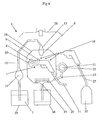
- Fig. 4 depicts the spray gun (1) after cleaning media (7) has entered and passed through the paint distributing passage (8).
- the spray nozzle (10) of the spray gun (1) is aimed into an open end (22) of a funnel-shaped nozzle (21).
- the spray gun (1) blows out remaining cleaning media and old paint from the paint distributing passage (8) into the funnel-shaped nozzle (21).
- As remaining cleaning media is blown out into the funnel-shaped nozzle (21) it is then guided via drainage (23) from the funnel-shaped nozzle (21) to the lower part of the chamber (18).
- the spray nozzle is wiped off on the wiping off element (20) inside the chamber (18) (not shown in figures).
- This wiping off performance can also be performed before blowing out the cleaning media and old paint from the paint distributing passage (8).
- cleaning media is splashed onto the exterior of the spray gun (1).
- Cleaning media and old paint which is on the exterior of the spray gun (1) is removed by pressurized air (32) which is led to an air nozzle (16) via a flexible member (27).
- the air nozzle (16) and the flexible member (27) are comprised in the cleaning unit.
- the cleaning unit (5) includes a means for ventilation (28), see Fig. 4 . Vapors and gases generated during cleaning and as well as during painting are guided into the means for ventilation (28).
- the means for ventilation (28) communicates with a unit known to a skilled person for handling the mentioned generated vapors and gases.
- Fig. 5 depicts the spray gun (1) when the cleaning process has initiated.
- the cleaning unit (5) includes a media delivering system (12) which communicates with the cleaning nozzle (6).
- the cleaning media (7) is fed to the cleaning nozzle (6) via a venturi nozzle (15).
- the venturi nozzle (15) is controlled by the valve (13).
- the valve (13) is integrated in the cleaning nozzle (6).
- air flows through the venturi nozzle (15) whereby cleaning media is drawn to the venturi nozzle (15).
- the cleaning media (7) and the air which has entered the venturi nozzle (15) are guided out through the cleaning nozzle (6). From the cleaning nozzle (6) the cleaning media (7) is mixed with air then guided into and through the paint distributing passage (8) as described above for Fig. 3 .
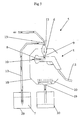
- Fig. 6 and Fig. 7 depict the cleaning of the spray gun (1) in accordance with another example of an embodiment of the invention.
- the cleaning unit (5) comprises a venturi nozzle (15) as described above in Fig. 5 .
- On the media delivering system (12) is a T-member (17) positioned between container (29) comprising the cleaning media (7) and the venturi nozzle (15) communicating with the cleaning nozzle (6).
- the T-member (17) has one part which is communicating with the container (29), one part which is communicating with the venturi nozzle (15) and the cleaning nozzle (6), and one part comprising a valve in which air is introduced into the T-member (17).
- the valve which air is introduced into the T-member may be any desired valve. When the valve in the T-member (17) is in an open position air is introduced into the T-member (17). When the valve in the T-member (17) is in a closed position no air can enter into the T-member (17).
- Fig. 6 depicts when the valve in the T-member (17) is in an open position. Air then flows through the T-member (17). The air, after entering the T-member (17), continues to the venturi nozzle (15) and then out through the cleaning nozzle (6). As air is introduced into the T-member (17) no cleaning media (7) from the container (29) is drawn up and led to the cleaning nozzle (6).
- Fig. 7 depicts when the valve in the T-member (17) is in a closed position.
- cleaning media due to the function of the venturi nozzle (15), as described above in relation to Fig. 5 is led to the venturi nozzle (15) and out through the cleaning nozzle (6) into the paint distributing passage (8) of the spray gun (1).
- Fig. 8 depicts a chamber (18) in accordance with an example of an embodiment of the invention where the chamber (18) comprises a second cleaning nozzle (36).
- the second cleaning nozzle (36) is located inside the chamber (18) on a side wall of the chamber (18).
- Fig. 8 further depicts another example of an embodiment of the invention where the chamber (18) comprises a vacuum tank (34).
- the vacuum tank (34) is connected to the chamber (18). However, it can also be located in the vicinity to the chamber (18).
- the vacuum tank comprises a receiving funnel (35), whereby the spray nozzle (10) of the spray gun (1) is placed into the receiving funnel (35) (not shown in figures).
- a low pressure contained in the vacuum tank (34) generates a vacuum effect into the vacuum tank (34), whereby cleaning media and old paint contained in the paint distributing passage (8) is drawn out from the paint distributing passage (8) via the spray nozzle (10) and into the vacuum tank (34).
- Fig. 8 further depicts an example of an embodiment of the invention where a washing means (37) is incorporated or connected to the chamber (18).
- the washing means (37) is constructed for receiving a paint cup and/or a lid and/or accessories to and for the spray gun (1) (not shown in figures), whereby the paint cup, lid and accessories to and for the spray gun is cleaned within in the washing means (37) in any desired manner.
Landscapes
- Details Or Accessories Of Spraying Plant Or Apparatus (AREA)
- Nozzles (AREA)
- Application Of Or Painting With Fluid Materials (AREA)
Claims (5)
- Verfahren zum Reinigen einer Spritzpistole (1), die mit einem Wegwerf-Farbbecher (3) arbeitet, wobei die Spritzpistole während der Reinigung in der Hand gehalten wird, wobei das Verfahren folgende Schritte aufweist:Entfernen des Wegwerf-Farbbechers (3) von der Spritzpistole (1); undPlatzieren der Spritzpistole (1) in einer Reinigungsposition innerhalb einer Reinigungseinheit (5) zum Reinigen der Spritzpistole;wobei die Reinigungseinheit (5) in einer oder in unmittelbarer Nähe einer Farbspritzkabine (2) oder einem Vorbereitungsbereich (31) angeordnet wird,dadurch gekennzeichnet,dass das Verfahren ferner folgende Schritte aufweist:Bereitstellen eines Reinigungsmittels (7) in Form eines Lösungsmittels;Zuführen des Reinigungsmittels (7) in eine Reinigungsdüse (8), wobei sich die Reinigungsdüse bei Aktivierung der Reinigungseinheit (5) öffnet und für einen Ausstrom des Reinigungsmittels sorgt;Leiten des Reinigungsmittels (7) in eine Farbverteilungspassage (8) im Inneren der Spritzpistole (1) durch einen Einlass (9) an der Spritzpistole zum Zuführen von Farbe zu der Spritzpistole; undAufbringen von Druck auf das Reinigungsmittel (7), während dieses die Spritzpistole (1) durchläuft.
- Verfahren zum Reinigen einer Spritzpistole (1) nach Anspruch 1,
dadurch gekennzeichnet, dass das Verfahren ferner folgenden Schritt aufweist:Aktivieren der Reinigungseinheit (5) durch Bewegen der Spritzpistole (1) in Richtung auf die Reinigungsdüse (6) an der Reinigungseinheit. - Verfahren zum Reinigen einer Spritzpistole (1) nach Anspruch 1,
dadurch gekennzeichnet, dass das Verfahren ferner folgenden Schritt aufweist:Aktivieren der Reinigungseinheit (5), indem der Einlass (9) der Spritzpistole (1) mit der Reinigungsdüse (6) in Kontakt gebracht wird und dadurch ein Ventil (13) in der Reinigungsdüse geöffnet wird. - Verfahren zum Reinigen einer Spritzpistole (1) nach Anspruch 1,
dadurch gekennzeichnet, dass das Verfahren ferner folgenden Schritt aufweist:Bereitstellen eines Pedals, das bei Betätigung den Reinigungsvorgang aktiviert, oderBereitstellen einer Taste an der Reinigungseinheit (5), die bei Betätigung den Reinigungsvorgang aktiviert, oderBereitstellen eines Sensors an der Reinigungseinheit (5), der bei Berührung oder wenn er einer Temperatur, Licht, Bewegung oder Schall ausgesetzt wird, den Reinigungsvorgang aktiviert. - Verfahren zum Reinigen einer Spritzpistole (1) nach einem der Ansprüche 1 bis 4,
dadurch gekennzeichnet, dass das Verfahren ferner folgenden Schritt aufweist:Bewegen des Reinigungsmittels (7) bei der Reinigung innerhalb der Farbverteilungspassage (8) sowohl in Rückwärtsrichtung als auch in Vorwärtsrichtung.
Applications Claiming Priority (2)
| Application Number | Priority Date | Filing Date | Title |
|---|---|---|---|
| US11/497,004 US7785420B2 (en) | 2006-08-01 | 2006-08-01 | Method for cleaning a spray gun |
| PCT/SE2007/000546 WO2008016321A1 (en) | 2006-08-01 | 2007-06-07 | An apparatus and method for cleaning a spray gun |
Publications (3)
| Publication Number | Publication Date |
|---|---|
| EP2046505A1 EP2046505A1 (de) | 2009-04-15 |
| EP2046505A4 EP2046505A4 (de) | 2011-04-13 |
| EP2046505B1 true EP2046505B1 (de) | 2015-03-04 |
Family
ID=38858085
Family Applications (1)
| Application Number | Title | Priority Date | Filing Date |
|---|---|---|---|
| EP07748209.9A Active EP2046505B1 (de) | 2006-08-01 | 2007-06-07 | Verfahren zur reinigung einer spritzpistole |
Country Status (10)
| Country | Link |
|---|---|
| US (1) | US7785420B2 (de) |
| EP (1) | EP2046505B1 (de) |
| CN (1) | CN201192669Y (de) |
| CA (1) | CA2659519C (de) |
| DE (1) | DE202007010385U1 (de) |
| ES (1) | ES2537958T3 (de) |
| FR (1) | FR2903332B3 (de) |
| IT (1) | ITTO20070424A1 (de) |
| RU (1) | RU2009102631A (de) |
| WO (1) | WO2008016321A1 (de) |
Cited By (1)
| Publication number | Priority date | Publication date | Assignee | Title |
|---|---|---|---|---|
| CN105032672A (zh) * | 2015-07-23 | 2015-11-11 | 山东朗法博粉末涂装科技有限公司 | Mdf板导电液喷涂设备 |
Families Citing this family (17)
| Publication number | Priority date | Publication date | Assignee | Title |
|---|---|---|---|---|
| DE102008027910B4 (de) * | 2008-03-11 | 2024-06-06 | B-TEC GmbH Geräte- und Anlagentechnik | Vorrichtung zum Reinigen von Lackier- und/oder Klebepistolen |
| DE102008064043A1 (de) * | 2008-12-19 | 2010-07-01 | Dürr Systems GmbH | Lackiervorrichtung und Verfahren zu deren Betrieb |
| ES2561046T3 (es) | 2008-12-19 | 2016-02-24 | Dürr Systems GmbH | Instalación de pintura y procedimiento para el funcionamiento de una instalación de pintura |
| FR2944221B1 (fr) | 2009-04-08 | 2012-03-09 | Fillon Technologies | Dispositif de nettoyage pour pistolet de pulverisation |
| DE102009018294B4 (de) * | 2009-04-21 | 2018-08-09 | Bayerische Motoren Werke Aktiengesellschaft | Mischvorrichtung |
| WO2011006170A2 (en) * | 2009-07-10 | 2011-01-13 | Microbial-Vac Systems, Inc. | System and method for cleaning contaminant collection equipment |
| SE534559C2 (sv) | 2010-02-24 | 2011-10-04 | Hedson Technologies Ab | Sprutpistoltvättanordning och metod för att anordna en sprutpistol däri, samt pistolhållare därför |
| GB2505692B (en) * | 2012-09-07 | 2018-07-11 | Ui Equipment Ltd | Spray gun washing apparatus and method |
| CN102989704A (zh) * | 2012-11-26 | 2013-03-27 | 吴江市金真缝纫机有限公司 | 喷气织机喷嘴的清洗装置及清洗方法 |
| DE102014006647A1 (de) * | 2014-05-07 | 2015-11-12 | Dürr Systems GmbH | Reinigungsgerät für einen Zerstäuber und zugehöriges Betriebsverfahren |
| CN105903619B (zh) * | 2016-05-19 | 2018-01-19 | 中银(宁波)电池有限公司 | 一种喷嘴清洁机构 |
| CN105903620B (zh) * | 2016-05-19 | 2018-01-19 | 中银(宁波)电池有限公司 | 一种喷嘴定时清洁机构 |
| CN107930935B (zh) * | 2017-11-30 | 2019-07-30 | 重庆市长寿区美全家具有限公司 | 一种家具喷漆装置 |
| CN109925078A (zh) * | 2018-10-16 | 2019-06-25 | 青岛大学附属医院 | 一种口腔科用口腔清洁装置 |
| CN111451222B (zh) * | 2020-03-18 | 2024-08-23 | 成都东日瑞姆机械有限公司 | 添加粉末组分多流道浇注的聚氨酯发泡设备 |
| FR3117910B1 (fr) * | 2020-12-18 | 2023-04-07 | Exel Ind | Robot, système et procédé de poudrage électrostatique |
| US12122350B2 (en) | 2021-02-22 | 2024-10-22 | Cnh Industrial America Llc | System and method for purging agricultural sprayer nozzles using air pressure data |
Family Cites Families (36)
| Publication number | Priority date | Publication date | Assignee | Title |
|---|---|---|---|---|
| US2726667A (en) | 1954-08-19 | 1955-12-13 | Northrop Aircraft Inc | Spray gun and cup cleaner |
| US3276988A (en) * | 1959-10-06 | 1966-10-04 | Anocut Eng Co | Electrolytic removal of work material |
| US3381845A (en) * | 1967-01-03 | 1968-05-07 | Roderick B. Macdonald | Disposable plastic container for spray guns |
| US3771539A (en) * | 1972-05-19 | 1973-11-13 | Santis B De | Paint gun cleaner |
| US3904431A (en) | 1974-08-08 | 1975-09-09 | David Dinerman | Spray-gun cleaners |
| US4025363A (en) | 1976-01-12 | 1977-05-24 | Benito De Santis | Spray equipment cleaner |
| US4324242A (en) * | 1980-10-03 | 1982-04-13 | Abbott Laboratories | Feminine syringe |
| US4570278A (en) * | 1983-02-25 | 1986-02-18 | The Kartridg Pak Co. | Portable polisher and buffs therefor |
| SE447799B (sv) | 1986-01-20 | 1986-12-15 | Stern Leif Einar | Anordning for att hos sprutpistoler rengora fergdistributionskanaler |
| US5213119A (en) | 1986-03-20 | 1993-05-25 | Safety-Kleen Corporation | Solvent recirculating type spray gun cleaner |
| US5174317A (en) | 1986-09-05 | 1992-12-29 | Herkules Equipment Corporation | Spray gun and associate parts washer and recycler |
| GB2195737B (en) | 1986-09-09 | 1991-01-30 | Leif Einar Stern | Container for hazardous detergents |
| CA1300366C (en) | 1986-11-10 | 1992-05-12 | Honda Giken Kogyo Kabushiki Kaisha | Method of and apparatus for cleaning paint spray guns |
| CA1293909C (en) | 1987-07-16 | 1992-01-07 | Soichiro Yamamoto | Apparatus for automatic cleaning of paint spray gun assemblies and their component parts |
| US4785836A (en) * | 1987-07-17 | 1988-11-22 | Soichiro Yamamoto | Spray washer |
| US4823820A (en) | 1987-07-28 | 1989-04-25 | Safety-Kleen Corp. | Solvent vapor collection and evacuation system |
| DE3734267A1 (de) | 1987-09-14 | 1989-03-23 | Gottlob Schwarzwaelder | Geraet zum halb- bzw. vollautomatischen reinigen von farb- und lackspritzpistolen od. dgl. sowie von farb- und lackverschmutzten gegenstaenden |
| DE3808801A1 (de) | 1988-03-16 | 1989-10-05 | Behr Industrieanlagen | Verfahren und vorrichtung zum reinigen einer spruehvorrichtung |
| US5183066A (en) * | 1991-04-02 | 1993-02-02 | General Dynamics Corp., Air Defense Systems Division | Spray nozzle cleaning apparatus and method |
| US5505387A (en) | 1995-01-23 | 1996-04-09 | Yaworski; Anthony | Assembly for use in a paint spray booth |
| US5513938A (en) * | 1995-04-03 | 1996-05-07 | International Marketing, Inc. | Wheel lift rotator |
| CA2238019C (en) | 1995-11-17 | 2004-05-11 | Crystal Cap Cleaners Inc. | Method and apparatus for cleaning spray guns |
| US5855218A (en) | 1995-12-04 | 1999-01-05 | Basf Corporation | Spray gun cleaning apparatus |
| US5704381A (en) | 1996-01-25 | 1998-01-06 | Northrop Grumman Corporation | Enclosed spray gun and accessories cleaning apparatus |
| ATE212402T1 (de) * | 1996-02-28 | 2002-02-15 | Internat Sanitary Ware Mfg Cy | Vorrichtung zum steuern einer gruppe von badezimmergeräten |
| IT1291747B1 (it) | 1997-05-16 | 1999-01-21 | Rosauto Srl | Apparecchiatura di lavaggio automatica e manuale a funzionamento variabile per pistole a spruzzo e loro componenti |
| DE29819052U1 (de) | 1998-10-26 | 2000-03-02 | J. Wagner Gmbh, 88048 Friedrichshafen | Fördervorrichtung |
| US20030127046A1 (en) | 2002-01-09 | 2003-07-10 | Harley-Davidson Motor Company Group, Inc. | Paint spray gun cleaner |
| CN2538433Y (zh) | 2002-02-21 | 2003-03-05 | 洽昌工业股份有限公司 | 喷漆枪的自动清洗装置 |
| ITMI20021707A1 (it) | 2002-07-31 | 2004-02-01 | Rosauto Srl | Dispositivo di lavaggio migliorato per una pistola a spruzzo |
| US20040128000A1 (en) * | 2002-12-26 | 2004-07-01 | Phillips Larry S. | Recipe control system and method |
| US6779535B2 (en) | 2003-01-21 | 2004-08-24 | Henry Drukarov | Paint brush cleaning device |
| JP4511371B2 (ja) | 2003-02-21 | 2010-07-28 | ジュサップ,フィリップ | 非接触スプレー器具洗浄装置 |
| DE102004044475B4 (de) | 2004-05-07 | 2008-10-16 | Bayerische Motoren Werke Aktiengesellschaft | Kupplungsstück |
| ITMI20041118A1 (it) | 2004-06-03 | 2004-09-03 | Rosauto Srl | Dispositivo di lavaggio dotato di zone di lavaggio automatico e manuale separate per pistole e spruzzo e loro componenti |
| WO2009044416A1 (en) | 2007-10-03 | 2009-04-09 | Power-One Italy S.P.A. | Method for reprogramming applications in embedded devices and related device |
-
2006
- 2006-08-01 US US11/497,004 patent/US7785420B2/en active Active
-
2007
- 2007-06-07 RU RU2009102631/05A patent/RU2009102631A/ru not_active Application Discontinuation
- 2007-06-07 CA CA2659519A patent/CA2659519C/en active Active
- 2007-06-07 WO PCT/SE2007/000546 patent/WO2008016321A1/en not_active Ceased
- 2007-06-07 ES ES07748209.9T patent/ES2537958T3/es active Active
- 2007-06-07 EP EP07748209.9A patent/EP2046505B1/de active Active
- 2007-06-14 IT IT000424A patent/ITTO20070424A1/it unknown
- 2007-06-20 FR FR0704394A patent/FR2903332B3/fr not_active Expired - Lifetime
- 2007-07-23 CN CNU2007201571462U patent/CN201192669Y/zh not_active Expired - Lifetime
- 2007-07-24 DE DE202007010385U patent/DE202007010385U1/de not_active Expired - Lifetime
Cited By (1)
| Publication number | Priority date | Publication date | Assignee | Title |
|---|---|---|---|---|
| CN105032672A (zh) * | 2015-07-23 | 2015-11-11 | 山东朗法博粉末涂装科技有限公司 | Mdf板导电液喷涂设备 |
Also Published As
| Publication number | Publication date |
|---|---|
| FR2903332A3 (fr) | 2008-01-11 |
| EP2046505A4 (de) | 2011-04-13 |
| ITTO20070424A1 (it) | 2007-09-13 |
| EP2046505A1 (de) | 2009-04-15 |
| ES2537958T3 (es) | 2015-06-16 |
| DE202007010385U1 (de) | 2008-01-10 |
| US7785420B2 (en) | 2010-08-31 |
| US20080029128A1 (en) | 2008-02-07 |
| RU2009102631A (ru) | 2010-09-10 |
| CA2659519A1 (en) | 2008-02-07 |
| WO2008016321A1 (en) | 2008-02-07 |
| CA2659519C (en) | 2017-01-24 |
| CN201192669Y (zh) | 2009-02-11 |
| FR2903332B3 (fr) | 2008-06-06 |
Similar Documents
| Publication | Publication Date | Title |
|---|---|---|
| EP2046505B1 (de) | Verfahren zur reinigung einer spritzpistole | |
| CA2680112C (en) | Cleaning device for cleaning spray guns | |
| KR100988659B1 (ko) | 비접촉식 스프레이 기구 세척 장비 | |
| EP1574262A1 (de) | Reinigungsgerät | |
| CN107683179B (zh) | 用于无气喷枪的压力供给附件适配器 | |
| WO2008084327A2 (en) | Paint gun washer station for paint guns and the like | |
| EP0443421B1 (de) | Vorrichtung zum Reinigen handbetriebener Spritzpistolen | |
| EP4446017A2 (de) | System zum waschen von spritzpistolen | |
| KR101932586B1 (ko) | 정전 분체도장용 분무장치 | |
| EP4043107B1 (de) | Sprühsystem mit rotierender abdeckung | |
| KR100268109B1 (ko) | 원단 수지 코팅액 분사장치 | |
| US7156919B2 (en) | Portable metallizing spray booth | |
| EP1386671B1 (de) | Verbesserte Reinigungsvorrichtung für eine Sprühpistole mit Schwerkraftbehälter | |
| JPH09262518A (ja) | 塗装ガン洗浄装置 | |
| CN210496891U (zh) | 喷射装置及蒸汽洗车机 | |
| JPH0330852A (ja) | 塗装ガン | |
| JP4059430B2 (ja) | 廃塗料回収装置 | |
| JP2002045737A (ja) | スプレーガン塗料通路の洗浄方法及び同洗浄装置 | |
| JP2540172Y2 (ja) | 塗料経路の洗浄装置 | |
| JPS6125888Y2 (de) | ||
| JP3483082B2 (ja) | 噴霧式塗装装置の噴霧口洗浄装置 | |
| JPH1119555A (ja) | スプレーガン洗浄方法及びスプレーガン洗浄装置 | |
| HK1138533B (en) | Cleaning device for cleaning spray guns | |
| JPH08168707A (ja) | スプレーガンのガン先洗浄方法および装置 | |
| KR19980024495A (ko) | 분체도료공급장치 |
Legal Events
| Date | Code | Title | Description |
|---|---|---|---|
| PUAI | Public reference made under article 153(3) epc to a published international application that has entered the european phase |
Free format text: ORIGINAL CODE: 0009012 |
|
| 17P | Request for examination filed |
Effective date: 20090122 |
|
| AK | Designated contracting states |
Kind code of ref document: A1 Designated state(s): AT BE BG CH CY CZ DE DK EE ES FI FR GB GR HU IE IS IT LI LT LU LV MC MT NL PL PT RO SE SI SK TR |
|
| AX | Request for extension of the european patent |
Extension state: AL BA HR MK RS |
|
| A4 | Supplementary search report drawn up and despatched |
Effective date: 20110316 |
|
| DAX | Request for extension of the european patent (deleted) | ||
| 17Q | First examination report despatched |
Effective date: 20140131 |
|
| RIC1 | Information provided on ipc code assigned before grant |
Ipc: B05B 7/24 20060101ALN20140718BHEP Ipc: B05B 15/02 20060101AFI20140718BHEP |
|
| GRAP | Despatch of communication of intention to grant a patent |
Free format text: ORIGINAL CODE: EPIDOSNIGR1 |
|
| RIC1 | Information provided on ipc code assigned before grant |
Ipc: B05B 7/24 20060101ALN20140917BHEP Ipc: B05B 15/02 20060101AFI20140917BHEP |
|
| INTG | Intention to grant announced |
Effective date: 20140929 |
|
| GRAS | Grant fee paid |
Free format text: ORIGINAL CODE: EPIDOSNIGR3 |
|
| GRAA | (expected) grant |
Free format text: ORIGINAL CODE: 0009210 |
|
| AK | Designated contracting states |
Kind code of ref document: B1 Designated state(s): AT BE BG CH CY CZ DE DK EE ES FI FR GB GR HU IE IS IT LI LT LU LV MC MT NL PL PT RO SE SI SK TR |
|
| REG | Reference to a national code |
Ref country code: GB Ref legal event code: FG4D |
|
| RIN1 | Information on inventor provided before grant (corrected) |
Inventor name: JOHANSSON, NIKLAS Inventor name: NORMAN, CHRISTIAN Inventor name: BEIJBOM, PETER |
|
| REG | Reference to a national code |
Ref country code: CH Ref legal event code: EP |
|
| REG | Reference to a national code |
Ref country code: IE Ref legal event code: FG4D |
|
| REG | Reference to a national code |
Ref country code: AT Ref legal event code: REF Ref document number: 713371 Country of ref document: AT Kind code of ref document: T Effective date: 20150415 |
|
| REG | Reference to a national code |
Ref country code: DE Ref legal event code: R096 Ref document number: 602007040482 Country of ref document: DE Effective date: 20150416 |
|
| REG | Reference to a national code |
Ref country code: FR Ref legal event code: PLFP Year of fee payment: 9 |
|
| REG | Reference to a national code |
Ref country code: CH Ref legal event code: NV Representative=s name: BOVARD AG, CH |
|
| REG | Reference to a national code |
Ref country code: ES Ref legal event code: FG2A Ref document number: 2537958 Country of ref document: ES Kind code of ref document: T3 Effective date: 20150616 |
|
| REG | Reference to a national code |
Ref country code: NL Ref legal event code: T3 |
|
| REG | Reference to a national code |
Ref country code: SE Ref legal event code: TRGR |
|
| REG | Reference to a national code |
Ref country code: AT Ref legal event code: MK05 Ref document number: 713371 Country of ref document: AT Kind code of ref document: T Effective date: 20150304 |
|
| PG25 | Lapsed in a contracting state [announced via postgrant information from national office to epo] |
Ref country code: FI Free format text: LAPSE BECAUSE OF FAILURE TO SUBMIT A TRANSLATION OF THE DESCRIPTION OR TO PAY THE FEE WITHIN THE PRESCRIBED TIME-LIMIT Effective date: 20150304 Ref country code: LT Free format text: LAPSE BECAUSE OF FAILURE TO SUBMIT A TRANSLATION OF THE DESCRIPTION OR TO PAY THE FEE WITHIN THE PRESCRIBED TIME-LIMIT Effective date: 20150304 |
|
| REG | Reference to a national code |
Ref country code: LT Ref legal event code: MG4D |
|
| PG25 | Lapsed in a contracting state [announced via postgrant information from national office to epo] |
Ref country code: AT Free format text: LAPSE BECAUSE OF FAILURE TO SUBMIT A TRANSLATION OF THE DESCRIPTION OR TO PAY THE FEE WITHIN THE PRESCRIBED TIME-LIMIT Effective date: 20150304 Ref country code: GR Free format text: LAPSE BECAUSE OF FAILURE TO SUBMIT A TRANSLATION OF THE DESCRIPTION OR TO PAY THE FEE WITHIN THE PRESCRIBED TIME-LIMIT Effective date: 20150605 Ref country code: LV Free format text: LAPSE BECAUSE OF FAILURE TO SUBMIT A TRANSLATION OF THE DESCRIPTION OR TO PAY THE FEE WITHIN THE PRESCRIBED TIME-LIMIT Effective date: 20150304 |
|
| PG25 | Lapsed in a contracting state [announced via postgrant information from national office to epo] |
Ref country code: CZ Free format text: LAPSE BECAUSE OF FAILURE TO SUBMIT A TRANSLATION OF THE DESCRIPTION OR TO PAY THE FEE WITHIN THE PRESCRIBED TIME-LIMIT Effective date: 20150304 Ref country code: RO Free format text: LAPSE BECAUSE OF FAILURE TO SUBMIT A TRANSLATION OF THE DESCRIPTION OR TO PAY THE FEE WITHIN THE PRESCRIBED TIME-LIMIT Effective date: 20150304 Ref country code: PT Free format text: LAPSE BECAUSE OF FAILURE TO SUBMIT A TRANSLATION OF THE DESCRIPTION OR TO PAY THE FEE WITHIN THE PRESCRIBED TIME-LIMIT Effective date: 20150706 Ref country code: EE Free format text: LAPSE BECAUSE OF FAILURE TO SUBMIT A TRANSLATION OF THE DESCRIPTION OR TO PAY THE FEE WITHIN THE PRESCRIBED TIME-LIMIT Effective date: 20150304 Ref country code: SK Free format text: LAPSE BECAUSE OF FAILURE TO SUBMIT A TRANSLATION OF THE DESCRIPTION OR TO PAY THE FEE WITHIN THE PRESCRIBED TIME-LIMIT Effective date: 20150304 |
|
| PG25 | Lapsed in a contracting state [announced via postgrant information from national office to epo] |
Ref country code: IS Free format text: LAPSE BECAUSE OF FAILURE TO SUBMIT A TRANSLATION OF THE DESCRIPTION OR TO PAY THE FEE WITHIN THE PRESCRIBED TIME-LIMIT Effective date: 20150704 Ref country code: PL Free format text: LAPSE BECAUSE OF FAILURE TO SUBMIT A TRANSLATION OF THE DESCRIPTION OR TO PAY THE FEE WITHIN THE PRESCRIBED TIME-LIMIT Effective date: 20150304 |
|
| REG | Reference to a national code |
Ref country code: DE Ref legal event code: R097 Ref document number: 602007040482 Country of ref document: DE |
|
| PLBE | No opposition filed within time limit |
Free format text: ORIGINAL CODE: 0009261 |
|
| STAA | Information on the status of an ep patent application or granted ep patent |
Free format text: STATUS: NO OPPOSITION FILED WITHIN TIME LIMIT |
|
| PG25 | Lapsed in a contracting state [announced via postgrant information from national office to epo] |
Ref country code: DK Free format text: LAPSE BECAUSE OF FAILURE TO SUBMIT A TRANSLATION OF THE DESCRIPTION OR TO PAY THE FEE WITHIN THE PRESCRIBED TIME-LIMIT Effective date: 20150304 Ref country code: MC Free format text: LAPSE BECAUSE OF FAILURE TO SUBMIT A TRANSLATION OF THE DESCRIPTION OR TO PAY THE FEE WITHIN THE PRESCRIBED TIME-LIMIT Effective date: 20150304 |
|
| 26N | No opposition filed |
Effective date: 20151207 |
|
| PG25 | Lapsed in a contracting state [announced via postgrant information from national office to epo] |
Ref country code: SI Free format text: LAPSE BECAUSE OF FAILURE TO SUBMIT A TRANSLATION OF THE DESCRIPTION OR TO PAY THE FEE WITHIN THE PRESCRIBED TIME-LIMIT Effective date: 20150304 Ref country code: LU Free format text: LAPSE BECAUSE OF FAILURE TO SUBMIT A TRANSLATION OF THE DESCRIPTION OR TO PAY THE FEE WITHIN THE PRESCRIBED TIME-LIMIT Effective date: 20150607 |
|
| REG | Reference to a national code |
Ref country code: IE Ref legal event code: MM4A |
|
| PG25 | Lapsed in a contracting state [announced via postgrant information from national office to epo] |
Ref country code: IE Free format text: LAPSE BECAUSE OF NON-PAYMENT OF DUE FEES Effective date: 20150607 |
|
| REG | Reference to a national code |
Ref country code: FR Ref legal event code: PLFP Year of fee payment: 10 |
|
| PG25 | Lapsed in a contracting state [announced via postgrant information from national office to epo] |
Ref country code: MT Free format text: LAPSE BECAUSE OF FAILURE TO SUBMIT A TRANSLATION OF THE DESCRIPTION OR TO PAY THE FEE WITHIN THE PRESCRIBED TIME-LIMIT Effective date: 20150304 |
|
| PG25 | Lapsed in a contracting state [announced via postgrant information from national office to epo] |
Ref country code: HU Free format text: LAPSE BECAUSE OF FAILURE TO SUBMIT A TRANSLATION OF THE DESCRIPTION OR TO PAY THE FEE WITHIN THE PRESCRIBED TIME-LIMIT; INVALID AB INITIO Effective date: 20070607 Ref country code: BG Free format text: LAPSE BECAUSE OF FAILURE TO SUBMIT A TRANSLATION OF THE DESCRIPTION OR TO PAY THE FEE WITHIN THE PRESCRIBED TIME-LIMIT Effective date: 20150304 |
|
| PG25 | Lapsed in a contracting state [announced via postgrant information from national office to epo] |
Ref country code: CY Free format text: LAPSE BECAUSE OF FAILURE TO SUBMIT A TRANSLATION OF THE DESCRIPTION OR TO PAY THE FEE WITHIN THE PRESCRIBED TIME-LIMIT Effective date: 20150304 |
|
| PG25 | Lapsed in a contracting state [announced via postgrant information from national office to epo] |
Ref country code: TR Free format text: LAPSE BECAUSE OF FAILURE TO SUBMIT A TRANSLATION OF THE DESCRIPTION OR TO PAY THE FEE WITHIN THE PRESCRIBED TIME-LIMIT Effective date: 20150304 |
|
| REG | Reference to a national code |
Ref country code: FR Ref legal event code: PLFP Year of fee payment: 11 |
|
| REG | Reference to a national code |
Ref country code: DE Ref legal event code: R079 Ref document number: 602007040482 Country of ref document: DE Free format text: PREVIOUS MAIN CLASS: B05B0015020000 Ipc: B05B0015500000 |
|
| REG | Reference to a national code |
Ref country code: FR Ref legal event code: PLFP Year of fee payment: 12 |
|
| P01 | Opt-out of the competence of the unified patent court (upc) registered |
Effective date: 20230706 |
|
| PGFP | Annual fee paid to national office [announced via postgrant information from national office to epo] |
Ref country code: GB Payment date: 20240522 Year of fee payment: 18 |
|
| PGFP | Annual fee paid to national office [announced via postgrant information from national office to epo] |
Ref country code: DE Payment date: 20240627 Year of fee payment: 18 |
|
| PGFP | Annual fee paid to national office [announced via postgrant information from national office to epo] |
Ref country code: NL Payment date: 20240625 Year of fee payment: 18 |
|
| PGFP | Annual fee paid to national office [announced via postgrant information from national office to epo] |
Ref country code: FR Payment date: 20240625 Year of fee payment: 18 |
|
| PGFP | Annual fee paid to national office [announced via postgrant information from national office to epo] |
Ref country code: SE Payment date: 20240522 Year of fee payment: 18 Ref country code: BE Payment date: 20240625 Year of fee payment: 18 |
|
| PGFP | Annual fee paid to national office [announced via postgrant information from national office to epo] |
Ref country code: IT Payment date: 20240619 Year of fee payment: 18 |
|
| PGFP | Annual fee paid to national office [announced via postgrant information from national office to epo] |
Ref country code: CH Payment date: 20240701 Year of fee payment: 18 Ref country code: ES Payment date: 20240710 Year of fee payment: 18 |
|
| REG | Reference to a national code |
Ref country code: DE Ref legal event code: R119 Ref document number: 602007040482 Country of ref document: DE |
|
| REG | Reference to a national code |
Ref country code: CH Ref legal event code: H13 Free format text: ST27 STATUS EVENT CODE: U-0-0-H10-H13 (AS PROVIDED BY THE NATIONAL OFFICE) Effective date: 20260127 |
|
| REG | Reference to a national code |
Ref country code: SE Ref legal event code: EUG |
|
| REG | Reference to a national code |
Ref country code: NL Ref legal event code: MM Effective date: 20250701 |
|
| GBPC | Gb: european patent ceased through non-payment of renewal fee |
Effective date: 20250607 |
|
| REG | Reference to a national code |
Ref country code: BE Ref legal event code: MM Effective date: 20250630 |
|
| PG25 | Lapsed in a contracting state [announced via postgrant information from national office to epo] |
Ref country code: NL Free format text: LAPSE BECAUSE OF NON-PAYMENT OF DUE FEES Effective date: 20250701 |
|
| PG25 | Lapsed in a contracting state [announced via postgrant information from national office to epo] |
Ref country code: GB Free format text: LAPSE BECAUSE OF NON-PAYMENT OF DUE FEES Effective date: 20250607 |
|
| PG25 | Lapsed in a contracting state [announced via postgrant information from national office to epo] |
Ref country code: DE Free format text: LAPSE BECAUSE OF NON-PAYMENT OF DUE FEES Effective date: 20260101 |
|
| PG25 | Lapsed in a contracting state [announced via postgrant information from national office to epo] |
Ref country code: BE Free format text: LAPSE BECAUSE OF NON-PAYMENT OF DUE FEES Effective date: 20250630 Ref country code: IT Free format text: LAPSE BECAUSE OF NON-PAYMENT OF DUE FEES Effective date: 20250607 |
|
| PG25 | Lapsed in a contracting state [announced via postgrant information from national office to epo] |
Ref country code: FR Free format text: LAPSE BECAUSE OF NON-PAYMENT OF DUE FEES Effective date: 20250630 |