EP2050973A2 - Fastening element - Google Patents
Fastening element Download PDFInfo
- Publication number
- EP2050973A2 EP2050973A2 EP08018156A EP08018156A EP2050973A2 EP 2050973 A2 EP2050973 A2 EP 2050973A2 EP 08018156 A EP08018156 A EP 08018156A EP 08018156 A EP08018156 A EP 08018156A EP 2050973 A2 EP2050973 A2 EP 2050973A2
- Authority
- EP
- European Patent Office
- Prior art keywords
- fastening element
- fastening
- element according
- legs
- components
- Prior art date
- Legal status (The legal status is an assumption and is not a legal conclusion. Google has not performed a legal analysis and makes no representation as to the accuracy of the status listed.)
- Withdrawn
Links
Images


Classifications
-
- F—MECHANICAL ENGINEERING; LIGHTING; HEATING; WEAPONS; BLASTING
- F16—ENGINEERING ELEMENTS AND UNITS; GENERAL MEASURES FOR PRODUCING AND MAINTAINING EFFECTIVE FUNCTIONING OF MACHINES OR INSTALLATIONS; THERMAL INSULATION IN GENERAL
- F16B—DEVICES FOR FASTENING OR SECURING CONSTRUCTIONAL ELEMENTS OR MACHINE PARTS TOGETHER, e.g. NAILS, BOLTS, CIRCLIPS, CLAMPS, CLIPS OR WEDGES; JOINTS OR JOINTING
- F16B5/00—Joining sheets or plates, e.g. panels, to one another or to strips or bars parallel to them
- F16B5/06—Joining sheets or plates, e.g. panels, to one another or to strips or bars parallel to them by means of clamps or clips
- F16B5/0607—Joining sheets or plates, e.g. panels, to one another or to strips or bars parallel to them by means of clamps or clips joining sheets or plates to each other
- F16B5/0621—Joining sheets or plates, e.g. panels, to one another or to strips or bars parallel to them by means of clamps or clips joining sheets or plates to each other in parallel relationship
-
- F—MECHANICAL ENGINEERING; LIGHTING; HEATING; WEAPONS; BLASTING
- F16—ENGINEERING ELEMENTS AND UNITS; GENERAL MEASURES FOR PRODUCING AND MAINTAINING EFFECTIVE FUNCTIONING OF MACHINES OR INSTALLATIONS; THERMAL INSULATION IN GENERAL
- F16B—DEVICES FOR FASTENING OR SECURING CONSTRUCTIONAL ELEMENTS OR MACHINE PARTS TOGETHER, e.g. NAILS, BOLTS, CIRCLIPS, CLAMPS, CLIPS OR WEDGES; JOINTS OR JOINTING
- F16B5/00—Joining sheets or plates, e.g. panels, to one another or to strips or bars parallel to them
- F16B5/02—Joining sheets or plates, e.g. panels, to one another or to strips or bars parallel to them by means of fastening members using screw-thread
- F16B5/0241—Joining sheets or plates, e.g. panels, to one another or to strips or bars parallel to them by means of fastening members using screw-thread with the possibility for the connection to absorb deformation, e.g. thermal or vibrational
-
- Y—GENERAL TAGGING OF NEW TECHNOLOGICAL DEVELOPMENTS; GENERAL TAGGING OF CROSS-SECTIONAL TECHNOLOGIES SPANNING OVER SEVERAL SECTIONS OF THE IPC; TECHNICAL SUBJECTS COVERED BY FORMER USPC CROSS-REFERENCE ART COLLECTIONS [XRACs] AND DIGESTS
- Y10—TECHNICAL SUBJECTS COVERED BY FORMER USPC
- Y10T—TECHNICAL SUBJECTS COVERED BY FORMER US CLASSIFICATION
- Y10T403/00—Joints and connections
- Y10T403/45—Flexibly connected rigid members
- Y10T403/455—Elastomer interposed between radially spaced members
- Y10T403/456—Elastomer encompasses shoulder on inner member
Definitions
- the invention relates to fastening element for connecting two components.
- the invention relates to a fastening element, by means of which two components can be connected to one another such that a predetermined relative movement between the components is possible.
- a fastening element by means of which two components can be connected to one another such that a predetermined relative movement between the components is possible.
- An example of this is the connection of two components which are concentric to one another and which can execute a slight relative movement in the radial and axial directions relative to each other, for example to compensate for thermal expansions.
- the invention has for its object to provide a fastener of the type mentioned, which with a simple structure and simple, cost manufacturability avoids the disadvantages of the prior art and ensures a precise storage of the components together.
- a fastening element which is integrally formed and comprises two parallel, preferably plate-shaped or strip-shaped legs, which are operationally connected via an elastic member which is integrally connected with the legs.
- the two legs are used for attachment to the two components to be connected, wherein each of the components is to be connected to one of the legs.
- the construction is selected such that one of the legs projects substantially at right angles from a first fastening part, which can be connected to a component.
- the other leg is preferably formed extended and has on its side a second fastening part, which can be connected to the other component.
- the fastening element according to the invention thus allows a precise concentric and axial positioning of two components while ensuring a limited, predetermined relative mobility in several directions of movement.
- the fastening element according to the invention is designed so that it in the loading direction, in which a relative movement preferably occurs, having a minimum moment of inertia. Furthermore, it is provided that the stiffness of the fastening element in the loading direction, in which no relative movement or only a minimum relative movement is allowed, is greatest.
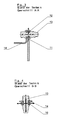
- the prior art shows typical fasteners for connecting two mutually concentric components 1, 2 (see. Fig. 6 ).
- a bearing plate 10 is provided, which is provided with a recess 11 in which a guide ring 12 is arranged with a U-shaped cross-section.
- the guide ring 12 passes through a bearing pin 13, which supports a second bearing plate 14. From the representations of 3 and 4 shows that a three-dimensional mobility between the first bearing plate 10 and the second bearing plate 14 is possible. Furthermore, it follows from the representations that a total of a complicated and complex overall structure is present.
- the Fig. 7 and 8th show an embodiment of the fastener according to the invention.
- This comprises a first leg 3 and a second leg 4 which is parallel to and spaced therefrom and which in each case (see in particular FIG Fig. 9 ) are connected at its free end with an elastic part 5.
- the elastic part 5, which is integrally connected to the two legs 3, 4, has a circular cross-section and is thus partially cylindrical (see. Fig. 7 and 8th ).
- a first fastening part 6 which is provided with a recess and on a component, for example, the component 2 (see. Fig. 13 ) is fixable by means of a screw connection.
- the first leg 3 is extended laterally and comprises a second fastening part 7, which is likewise provided with a fastening recess in order to be attached to the component 1 (FIG. Fig. 13 ) to be screwed.
- the Fig. 9 and 11 each show the directions of movement in three dimensions.
- the Fig. 12 shows a side view, which results in the part-circular cross-section of the elastic member 5, the together with the in Fig. 10 shown cross section leads to the mentioned elastic properties.
- the fastening element according to the invention is thus characterized by a simple structure and a simple construction, which can be exactly predetermined by suitable dimensioning and material selection.
- the wear is minimal compared to the prior art, resulting in a much longer life. Due to the lower assembly costs and the small number of parts results in a significant cost savings. In addition, there is an advantage in terms of weight reduction.
Landscapes
- Engineering & Computer Science (AREA)
- General Engineering & Computer Science (AREA)
- Mechanical Engineering (AREA)
- Insertion Pins And Rivets (AREA)
- Mutual Connection Of Rods And Tubes (AREA)
- Connection Of Plates (AREA)
Abstract
Die Erfindung bezieht sich auf ein Befestigungselement zur Verbindung zweier Bauelemente 1, 2, wobei das Befestigungselement eine Verbindung der Bauelemente 1, 2 mit einer vorgegebenen Relativbewegungsmöglichkeit zueinander gewährleistet, wobei das Befestigungselement zwei zueinander im Wesentlichen parallele Schenkel 3, 4 umfasst, welche an ihren freien Endbereichen mittels eines einstückig mit den Schenkeln 3, 4 ausgebildeten elastischen Teils 5 verbunden sind, wobei das elastische Teil 5 in der Seitenansicht mit einem teilkreisförmigen Querschnitt versehen ist.

Description
Die Erfindung bezieht sich auf Befestigungselement zur Verbindung zweier Bauelemente.The invention relates to fastening element for connecting two components.
Im Einzelnen bezieht sich die Erfindung auf ein Befestigungselement, mittels dessen zwei Bauelemente so miteinander verbindbar sind, dass eine vorgegebene Relativbewegung zwischen den Bauelementen möglich ist. Als Beispiel hierfür ist die Verbindung zweier zueinander konzentrischer Bauelemente zu nennen, welche in radialer und in axialer Richtung zueinander eine geringfügige Relativbewegung ausführen können, beispielsweise um Wärmeausdehnungen auszugleichen.In detail, the invention relates to a fastening element, by means of which two components can be connected to one another such that a predetermined relative movement between the components is possible. An example of this is the connection of two components which are concentric to one another and which can execute a slight relative movement in the radial and axial directions relative to each other, for example to compensate for thermal expansions.
Aus dem Stand der Technik ist es bekannt, Befestigungselemente vorzusehen, die entweder durch geeignete Werkstoffwahl (elastische Buchsen oder Ähnliches) oder durch konstruktive Maßnahmen (Langlöcher, Ausnehmungen größeren Durchmessers für Führungszapfen mit geringerem Durchmesser) die gewünschte Bewegbarkeit bei gleichzeitig definierter Lagerung schaffen.From the prior art it is known to provide fasteners that create the desired mobility with simultaneously defined storage either by suitable choice of material (elastic bushes or the like) or by constructive measures (slots, larger diameter recesses for guide pin with a smaller diameter).
Als nachteilig hierbei erweist es sich, dass die aus dem Stand der Technik bekannten Konstruktionen aufwendig in der Herstellung und in der Montage sind und aus vielen Einzelteilen bestehen. Durch den komplizierten Aufbau ergibt sich ein erheblicher Verschleiß, der zu Lockerungen oder Rattern führen kann und die Lebensdauer des Befestigungselementes insgesamt deutlich herabsetzt.A disadvantage here it turns out that the known from the prior art constructions are expensive to manufacture and in the assembly and consist of many items. Due to the complicated structure results in considerable wear, which can lead to loosening or chattering and significantly reduces the life of the fastener as a whole.
Der Erfindung liegt die Aufgabe zugrunde, ein Befestigungselement der eingangs genannten Art zu schaffen, welches bei einfachem Aufbau und einfacher, kostengünstiger Herstellbarkeit die Nachteile des Standes der Technik vermeidet und eine präzise Lagerung der Bauteile aneinander sicherstellt.The invention has for its object to provide a fastener of the type mentioned, which with a simple structure and simple, cost manufacturability avoids the disadvantages of the prior art and ensures a precise storage of the components together.
Erfindungsgemäß wird diese Aufgabe durch die Merkmalskombination des Anspruchs 1 gelöst, die Unteransprüche zeigen weitere vorteilhafte Ausgestaltungen der Erfindung.According to the invention this object is achieved by the combination of features of
Erfindungsgemäß ist somit ein Befestigungselement vorgesehen, welches einstückig ausgebildet ist und zwei zueinander parallele, bevorzugterweise plattenförmige oder streifenförmige Schenkel umfasst, welche über ein elastisches Teil, welches einstückig mit den Schenkeln verbunden ist, betriebsverbunden sind. Die beiden Schenkel dienen zur Befestigung an den beiden zu verbindenden Bauelementen, wobei jedes der Bauelemente mit einem der Schenkel zu verbinden ist. Bevorzugterweise ist dabei die Konstruktion so gewählt, dass von einem der Schenkel im Wesentlichen rechtwinklig ein erstes Befestigungsteil absteht, welches mit einem Bauteil verbindbar ist. Der andere Schenkel ist bevorzugterweise verlängert ausgebildet und weist an seiner Seite ein zweites Befestigungsteil auf, welches mit dem anderen Bauteil verbunden werden kann.According to the invention a fastening element is thus provided, which is integrally formed and comprises two parallel, preferably plate-shaped or strip-shaped legs, which are operationally connected via an elastic member which is integrally connected with the legs. The two legs are used for attachment to the two components to be connected, wherein each of the components is to be connected to one of the legs. Preferably, the construction is selected such that one of the legs projects substantially at right angles from a first fastening part, which can be connected to a component. The other leg is preferably formed extended and has on its side a second fastening part, which can be connected to the other component.
Das erfindungsgemäße Befestigungselement erlaubt somit eine präzise konzentrische und axiale Positionierung zweier Bauelemente unter gleichzeitiger Gewährleistung einer begrenzten, vorgegebenen relativen Bewegbarkeit in mehreren Bewegungsrichtungen.The fastening element according to the invention thus allows a precise concentric and axial positioning of two components while ensuring a limited, predetermined relative mobility in several directions of movement.
Erfindungsgemäß wird somit ein einziges, einstückiges Befestigungselement geschaffen, welches kostengünstig herstellbar ist und bei seiner Montage nur einen minimalen Aufwand erfordert.According to the invention thus a single, one-piece fastener is created, which is inexpensive to produce and requires only minimal effort in its installation.
Das erfindungsgemäße Befestigungselement ist dabei so gestaltet, dass es in der Belastungsrichtung, in welcher eine Relativbewegung bevorzugt auftritt, ein minimales Trägheitsmoment aufweist. Weiterhin ist vorgesehen, dass die Steifheit des Befestigungselementes in der Belastungsrichtung, in der keine Relativbewegung oder nur eine minimale Relativbewegung erlaubt ist, am größten ist.The fastening element according to the invention is designed so that it in the loading direction, in which a relative movement preferably occurs, having a minimum moment of inertia. Furthermore, it is provided that the stiffness of the fastening element in the loading direction, in which no relative movement or only a minimum relative movement is allowed, is greatest.
Somit ist erfindungsgemäß unter Verwendung des Befestigungselements eine radiale Bewegung und eine Umfangsbewegung zwischen zwei zu verbindenden Bauelementen möglich, wobei das erfindungsgemäße Befestigungselement lediglich auf Biegung beansprucht wird. In der anderen Richtung, in welcher eine Bewegung im Wesentlichen verhindert werden soll, ergibt sich ein Höchstmaß an Steifigkeit.Thus, according to the invention using the fastener, a radial movement and a circumferential movement between two components to be connected is possible, wherein the fastening element according to the invention is claimed only on bending. In the other direction, in which a movement is to be prevented substantially, results in a maximum of rigidity.
Im Folgenden wird die Erfindung anhand eines Ausführungsbeispiels in Verbindung mit der Zeichnung beschrieben. Dabei zeigt:
- Fig. 1
- eine perspektivische Ansicht eines Befestigungselements gemäß dem Stand der Technik,
- Fig. 2
- eine Seitenansicht des in
Fig. 1 gezeigten Befestigungselements, - Fig. 3
- eine Schnittansicht längs der Linie A-A von
Fig. 2 , - Fig. 4
- eine Schnittansicht längs der Linie B-B von
Fig. 2 , - Fig. 5
- eine perspektivische Ansicht analog
Fig. 1 , - Fig. 6
- eine vereinfachte Darstellung der Anwendung des aus dem Stand der Technik bekannten Befestigungselements zur Verbindung zweier Bauelemente,
- Fig. 7
- eine perspektivische Ansicht eines erfindungsgemäßen Befestigungselements,
- Fig. 8
- eine weitere perspektivische Ansicht des in
Fig. 7 gezeigten Befestigungselements, - Fig. 9
- eine Seitenansicht des Befestigungselements der
Fig. 7 und8 , - Fig. 10
- eine Schnittansicht längs der Linie A-A von
Fig. 9 , - Fig. 11
- eine Draufsicht auf das Befestigungselement der
Fig. 7 bis 9 , - Fig. 12
- eine Schnittansicht längs der Linie B-B von
Fig. 11 , und - Fig. 13
- eine Ansicht, analog
Fig. 6 der beispielhaften Verwendung des erfindungsgemäßen Befestigungselements.
- Fig. 1
- a perspective view of a fastener according to the prior art,
- Fig. 2
- a side view of the in
Fig. 1 shown fastener, - Fig. 3
- a sectional view taken along the line AA of
Fig. 2 . - Fig. 4
- a sectional view taken along the line BB of
Fig. 2 . - Fig. 5
- a perspective view analog
Fig. 1 . - Fig. 6
- a simplified representation of the application of the known from the prior art fastener for connecting two components,
- Fig. 7
- a perspective view of a fastener according to the invention,
- Fig. 8
- another perspective view of the in
Fig. 7 shown fastener, - Fig. 9
- a side view of the fastener of
Fig. 7 and8th . - Fig. 10
- a sectional view taken along the line AA of
Fig. 9 . - Fig. 11
- a plan view of the fastener of
Fig. 7 to 9 . - Fig. 12
- a sectional view taken along the line BB of
Fig. 11 , and - Fig. 13
- a view, analog
Fig. 6 the exemplary use of the fastener according to the invention.
Der Stand der Technik zeigt typische Befestigungselemente zur Verbindung zweier zueinander konzentrischer Bauelemente 1, 2 (sh.
Die
Von dem zweiten Schenkel 4 aus erstreckt sich im Wesentlichen senkrecht ein erstes Befestigungsteil 6, welches mit einer Ausnehmung versehen ist und an einem Bauteil, beispielsweise dem Bauteil 2 (sh.
Der erste Schenkel 3 ist seitlich verlängert und umfasst ein zweites Befestigungsteil 7, welches ebenfalls mit einer Befestigungs-Ausnehmung versehen ist, um an dem Bauteil 1 (
Die
Demgegenüber ist bei einer Relativbewegung längs der senkrechten Pfeile gemäß
Die
Auch bei einer Verformung gemäß den horizontalen Pfeilen der
Somit sind radiale Bewegungen und Umfangsbewegungen der Bauelemente 1 und 2 leicht möglich, da das erfindungsgemäße Befestigungselement über den Querschnitt A-A (
Das erfindungsgemäße Befestigungselement zeichnet sich somit durch einen einfachen Aufbau und eine einfache Konstruktionsweise aus, welche durch geeignete Dimensionierung und Materialauswahl exakt vorbestimmbar ist. Der Verschleiß ist, im Vergleich zum Stand der Technik minimal, so dass sich eine weitaus höhere Lebensdauer ergibt. Durch den geringeren Montageaufwand und durch die geringe Anzahl der Teile ergibt sich eine erhebliche Kosteneinsparung. Zusätzlich ergibt sich ein Vorteil hinsichtlich der Gewichtsreduzierung.The fastening element according to the invention is thus characterized by a simple structure and a simple construction, which can be exactly predetermined by suitable dimensioning and material selection. The wear is minimal compared to the prior art, resulting in a much longer life. Due to the lower assembly costs and the small number of parts results in a significant cost savings. In addition, there is an advantage in terms of weight reduction.
- 11
- Bauelementmodule
- 22
- Bauelementmodule
- 33
- Erster SchenkelFirst leg
- 44
- Zweiter SchenkelSecond thigh
- 55
- Elastisches TeilElastic part
- 66
- Erstes BefestigungsteilFirst fastening part
- 77
- Zweites BefestigungsteilSecond fastening part
- 88th
- Elastische neutrale LinieElastic neutral line
- 99
- Befestigungsausnehmungmounting recess
- 1010
- Erste LagerplatteFirst bearing plate
- 1111
- Ausnehmungrecess
- 1212
- Führungsringguide ring
- 1313
- Lagerzapfenpivot
- 1414
- Zweite LagerplatteSecond bearing plate
Claims (9)
Applications Claiming Priority (1)
| Application Number | Priority Date | Filing Date | Title |
|---|---|---|---|
| DE102007050159A DE102007050159A1 (en) | 2007-10-19 | 2007-10-19 | fastener |
Publications (2)
| Publication Number | Publication Date |
|---|---|
| EP2050973A2 true EP2050973A2 (en) | 2009-04-22 |
| EP2050973A3 EP2050973A3 (en) | 2010-06-30 |
Family
ID=40184930
Family Applications (1)
| Application Number | Title | Priority Date | Filing Date |
|---|---|---|---|
| EP08018156A Withdrawn EP2050973A3 (en) | 2007-10-19 | 2008-10-16 | Fastening element |
Country Status (3)
| Country | Link |
|---|---|
| US (1) | US20090103975A1 (en) |
| EP (1) | EP2050973A3 (en) |
| DE (1) | DE102007050159A1 (en) |
Families Citing this family (2)
| Publication number | Priority date | Publication date | Assignee | Title |
|---|---|---|---|---|
| DE102011103158B4 (en) | 2011-06-01 | 2015-06-03 | Rolls-Royce Deutschland Ltd & Co Kg | Aircraft gas turbine with a bearing of a thermal deicing pipe element |
| DE102011106964A1 (en) | 2011-07-08 | 2013-01-10 | Rolls-Royce Deutschland Ltd & Co Kg | Gas turbine engine, particularly turbomachine for aircraft, has fan, core engine surrounded by adjacent flow channel and cladding element comprising exhaust area, where cladding element is supported elastically on turbine housing |
Family Cites Families (13)
| Publication number | Priority date | Publication date | Assignee | Title |
|---|---|---|---|---|
| US1366321A (en) * | 1920-08-03 | 1921-01-18 | Bernard J Kahn | Combined clip and spacer for electric conduits |
| FR2207543A5 (en) * | 1972-11-20 | 1974-06-14 | Setm Equipements | |
| US4482124A (en) * | 1977-10-07 | 1984-11-13 | General Electric Company | Torsional vibration isolating motor mounting arrangement and method of making the same |
| US4572472A (en) * | 1982-06-02 | 1986-02-25 | Westinghouse Electric Corp. | Electric motor flexible mounting system and method of assembly |
| US4597555A (en) * | 1983-09-02 | 1986-07-01 | Franklin Electric Co., Inc. | Electric motor mount |
| US4991801A (en) * | 1990-03-01 | 1991-02-12 | Trumbull Terry N | Universal support strap |
| GB2268993B (en) * | 1992-07-22 | 1995-02-15 | Nissan Europ Tech Centre | Vehicle body jointing bracket |
| DK173276B1 (en) * | 1998-02-05 | 2000-06-05 | Kongskilde Ind As | Clamp, method of manufacture of clamp, and agricultural machine using the clamp |
| US6761343B2 (en) * | 2001-06-13 | 2004-07-13 | York International Corp. | Single-piece motor mount |
| DE102004041685B3 (en) * | 2004-08-26 | 2006-05-04 | Bayer Materialscience Ag | composite component |
| CN101147024B (en) * | 2005-03-24 | 2010-05-19 | 尼尔·安德鲁·罗伯茨 | Temporary support structure for use in installing or removing components |
| US20080011909A1 (en) * | 2006-01-09 | 2008-01-17 | Enzo Daddario | Drinking straw holder |
| DE102006008382A1 (en) * | 2006-02-21 | 2007-08-30 | Ford Global Technologies, LLC, Dearborn | Spring element for arrangement for connecting two parts with different thermal expansion has curved flexible flanges that transition into angled flanges predominantly perpendicular to flat central contact region |
-
2007
- 2007-10-19 DE DE102007050159A patent/DE102007050159A1/en not_active Withdrawn
-
2008
- 2008-10-16 EP EP08018156A patent/EP2050973A3/en not_active Withdrawn
- 2008-10-20 US US12/289,043 patent/US20090103975A1/en not_active Abandoned
Also Published As
| Publication number | Publication date |
|---|---|
| EP2050973A3 (en) | 2010-06-30 |
| US20090103975A1 (en) | 2009-04-23 |
| DE102007050159A1 (en) | 2009-04-23 |
Similar Documents
| Publication | Publication Date | Title |
|---|---|---|
| EP2184029B1 (en) | Orthodontic expansion screw | |
| EP2713818B1 (en) | Catching locking mechanism for pieces of furniture | |
| DE102008009608A1 (en) | Planar element and clamping device combination, has planar element including profile rib for clamping device, where profile rib is formed with constrictions that oppose one another, and constrictions form undercuts for clamping device | |
| EP3622153B1 (en) | Furniture drive | |
| DE102012101614A1 (en) | Device for closing a housing of a connector | |
| DE102013216881A1 (en) | linear actuator | |
| DE102010003789A1 (en) | Elastic bearing, particularly for suspending exhaust system on car body floor pan of motor vehicle, has base plate for stationary mounting, which has two recesses which allow passage of fastening elements for bearing | |
| EP2050973A2 (en) | Fastening element | |
| EP1662155B1 (en) | Fixed plastic part for a vehicle | |
| EP3819645A1 (en) | Reinforcement element for reinforcing a test contactor system, use and method for mounting a test contactor system | |
| DE102018118983B3 (en) | Connecting arrangement for a hinge assembly and hinge assembly for adjusting a rear spoiler | |
| EP2407062B1 (en) | Clamping device | |
| DE19740799B4 (en) | damping element | |
| DE102012017979B4 (en) | spindle drive | |
| EP4216382A1 (en) | Arrangement with a mounting rail and housings arranged on one another | |
| DE202010004534U1 (en) | Fastening device with clamping screw | |
| DE10320737A1 (en) | Anti vibration mounting for motor vehicle test control housing has stainless steel wires extending between holder plates bolted to vehicle frame and housing | |
| DE102015225283A1 (en) | Differential bearing assembly | |
| EP3044534B1 (en) | Assembly system for securing an attachment part to a c-rail | |
| DE102005044127B4 (en) | Carrier part for a busbar support and busbar support | |
| DE102006017224A1 (en) | Anti-roll bar fastening device for motor vehicle, has bearing unit surrounding section of anti-roll bar, and clamp-shaped component for retaining bearing unit and section of bar, where fastening units fasten clamp-shaped component | |
| DE102018204195A1 (en) | Spindle drive and comfort drive with a spindle drive | |
| DE102007039574A1 (en) | Device for mounting gear unit on bearing point of assembly structure of vehicle, has axial bearing, which comprises multiple elastomer bodies arranged parallel in axial direction for flexible mounting of gear unit | |
| DE102006041803A1 (en) | Electrical device e.g. relay or non-electrical device fixing device, for holding groove of e.g. top hat rail, has compression spring unit acting in mounting end position on contact surface of mounting rail | |
| DE102004052636B3 (en) | Component fixing fitting for cladding of vehicle allows component to move between carrier element and holding element |
Legal Events
| Date | Code | Title | Description |
|---|---|---|---|
| PUAI | Public reference made under article 153(3) epc to a published international application that has entered the european phase |
Free format text: ORIGINAL CODE: 0009012 |
|
| AK | Designated contracting states |
Kind code of ref document: A2 Designated state(s): AT BE BG CH CY CZ DE DK EE ES FI FR GB GR HR HU IE IS IT LI LT LU LV MC MT NL NO PL PT RO SE SI SK TR |
|
| AX | Request for extension of the european patent |
Extension state: AL BA MK RS |
|
| PUAL | Search report despatched |
Free format text: ORIGINAL CODE: 0009013 |
|
| AK | Designated contracting states |
Kind code of ref document: A3 Designated state(s): AT BE BG CH CY CZ DE DK EE ES FI FR GB GR HR HU IE IS IT LI LT LU LV MC MT NL NO PL PT RO SE SI SK TR |
|
| AX | Request for extension of the european patent |
Extension state: AL BA MK RS |
|
| RIC1 | Information provided on ipc code assigned before grant |
Ipc: E04B 1/26 20060101ALI20100527BHEP Ipc: F16B 5/06 20060101AFI20090109BHEP |
|
| AKY | No designation fees paid | ||
| STAA | Information on the status of an ep patent application or granted ep patent |
Free format text: STATUS: THE APPLICATION IS DEEMED TO BE WITHDRAWN |
|
| 18D | Application deemed to be withdrawn |
Effective date: 20110104 |