EP2052639A1 - Reißverschluss - Google Patents
Reißverschluss Download PDFInfo
- Publication number
- EP2052639A1 EP2052639A1 EP07254217A EP07254217A EP2052639A1 EP 2052639 A1 EP2052639 A1 EP 2052639A1 EP 07254217 A EP07254217 A EP 07254217A EP 07254217 A EP07254217 A EP 07254217A EP 2052639 A1 EP2052639 A1 EP 2052639A1
- Authority
- EP
- European Patent Office
- Prior art keywords
- zipper
- teeth elements
- male
- elements
- female
- Prior art date
- Legal status (The legal status is an assumption and is not a legal conclusion. Google has not performed a legal analysis and makes no representation as to the accuracy of the status listed.)
- Withdrawn
Links
- 239000002184 metal Substances 0.000 claims description 14
- 238000009434 installation Methods 0.000 claims description 10
- 238000004519 manufacturing process Methods 0.000 description 3
- 239000004677 Nylon Substances 0.000 description 2
- 239000000463 material Substances 0.000 description 2
- 239000007769 metal material Substances 0.000 description 2
- 229920001778 nylon Polymers 0.000 description 2
- 230000003796 beauty Effects 0.000 description 1
- 238000012986 modification Methods 0.000 description 1
- 230000004048 modification Effects 0.000 description 1
- 239000004033 plastic Substances 0.000 description 1
- 229920003023 plastic Polymers 0.000 description 1
- 239000011347 resin Substances 0.000 description 1
- 229920005989 resin Polymers 0.000 description 1
Images


Classifications
-
- A—HUMAN NECESSITIES
- A44—HABERDASHERY; JEWELLERY
- A44B—BUTTONS, PINS, BUCKLES, SLIDE FASTENERS, OR THE LIKE
- A44B19/00—Slide fasteners
- A44B19/02—Slide fasteners with a series of separate interlocking members secured to each stringer tape
-
- A—HUMAN NECESSITIES
- A44—HABERDASHERY; JEWELLERY
- A44B—BUTTONS, PINS, BUCKLES, SLIDE FASTENERS, OR THE LIKE
- A44B19/00—Slide fasteners
- A44B19/42—Making by processes not fully provided for in one other class, e.g. B21D53/50, B21F45/18, B22D17/16, B29D5/00
Definitions
- the present invention relates to zippers and more particularly, to a metal zipper, which uses a guide groove in a slider body to guide hook strips of male teeth elements in and out of respective hook holes of female teeth elements, thereby closing or opening the zipper tapes.
- a conventional zipper is generally comprised of two zipper tapes, a male teeth chain, a female teeth chain, a slider body, two pins, a top stop, and a bottom stop.
- the male and female teeth chains are engaged together to close the zipper tapes or disengaged from each other to open the zipper tapes.
- the male and female teeth chains may be made of metal, plastics, nylon, or any of a variety of other materials.
- a zipper can be made in any of a variety of forms, such as close end, open end, X type, or O type.
- the male and female teeth chains of a conventional zipper are respectively comprised of a series of male tooth and a series of female tooth and driven by the slider body into the engaged position or disengaged position. Exemplars are seen in US PAT Nos. 7,036,191 ; 6,588,072 ; 4,099,301 ; 3,872,551 ; 1,934,084 .
- Other conventional metal, resin, or nylon zippers have similar male and female teeth chain structures.
- the zipper is comprised of two zipper tapes, a series of male teeth elements provided at one zipper tape, a series of female teeth elements provided at the other zipper tape, and a slider body movable over the male teeth elements and the female teeth elements to lock the male teeth elements and the female teeth elements or to unlock the male teeth elements from the female teeth elements.
- the female teeth elements each have a receiving portion and a hook hole on the outer side of the receiving portion.
- the male teeth elements each have a hook strip guided by the slider body into and out of the hook holes of the female teeth elements.
- the slider body has a guide groove on the inside for guiding the hook strips of the male teeth elements into and out of the hook holes of the receiving portions of the female teeth elements accurately without deviation when the slider body is moved over the male and female teeth elements.
- the male teeth elements and the female teeth elements can be independent elements separately fastened to the zipper tapes.
- the male teeth elements can be made in integrity and then affixed to one zipper tape
- the female teeth elements can be made in integrity and affixed to the other zipper tape.
- the male teeth elements and the female teeth elements can be made of a metal material so that the zipper cause a sense of ancient style beauty.
- the split tube-like bases of the female teeth elements cover the periphery of the cylindrical flange of the associating zipper tape such that the receiving portions of the female teeth elements are kept in an enclosed status relative to the cylindrical flange of the associating zipper tape.
- the clamping strips and/or split tube-like bases of the male teeth elements and female teeth elements have spurs for engaging into the zipper tapes to secure the respective male teeth elements and female teeth elements firmly to the respective zipper tapes.
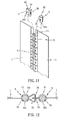
- a zipper in accordance with the present invention is shown comprised of two zipper tapes 1, male teeth elements 2, female teeth elements 3, and a slider body 4.
- the zipper tapes 1 each have a cylindrical flange 11 extending along the length at one side.
- the male teeth elements 2 are arranged in series along one side of one zipper tape 1, each comprising a split tube-like base 22 fastened to the cylindrical flange 11 of the associating zipper tape 1, a hook strip 21 perpendicularly extending from the periphery of the split tube-like base 22, and two clamping strips 23 extending from the split tube-like base 22 and clamped on the top and bottom surface of the associating zipper tape 1 to secure the split tube-like base 22 to the cylindrical flange 11 of the associating zipper tape 1 firmly.
- the split tube-like base 22 can be made having a hole 221 at one side or each of two opposite sides to enhance engagement between the split tube-like base 22 and the cylindrical flange 11 of the associating zipper tape 1.
- the hook strip 21 has a bend portion 211 extending from the periphery of the split tube-like base 22, and a hook portion 212 extending from one end of the bend portion 211 remote from the split tube-like base 22.
- the female teeth elements 3 are arranged in series along one side of the other zipper tape 1 to match the male teeth elements 2, each comprising a split tube-like base 33 fastened to the cylindrical flange 11 of the associating zipper tape 1, a hollow receiving portion 32 protruded from the periphery of the split tube-like base 33 at one side, a hook hole 31 on the outer side of the hollow retaining portion 32, and two clamping strips 34 extending from the split tube-like base 33 and clamped on the top and bottom surface of the associating zipper tape 1 to secure the split tube-like base 33 to the cylindrical flange 11 of the associating zipper tape 1 firmly (the clamping strips 23 or 34 of the male teeth elements 2 or female teeth elements 3 may be eliminated).
- the split tube-like base 33 can be made having a hole 331 at one side or each of two opposite sides to enhance engagement between the split tube-like base 33 and the cylindrical flange 11 of the associating zipper tape 1.
- the slider body 4 is movable over the male teeth elements 2 and the female teeth elements 3 to force the male teeth elements 2 into engagement with the female teeth elements 3 or to separate the male teeth elements 2 from the female teeth elements 3, having a guide groove 41 (see FIG. 2 ) for guiding the hook strip 21 of each male teeth element 2 into the hook hole 31 of the respective female teeth element 3. Further, a pull-tab 42 is coupled to the slider body 4.
- the guide groove 41 of the slider body 4 is adapted for the passing of the hook strip 21 of each male teeth element 2 when the slider body 4 is moving over the male teeth elements 2 and the female teeth elements 3 and for guiding the hook strip 21 of each male teeth element 2 toward a predetermined direction so that the hook strips 21 of the male teeth elements 2 can be respectively and accurately forced into the hook holes 31 of the female teeth elements 3 and kept in positive engagement with the receiving portions 32 of the female teeth elements 3.
- the invention can be made in the form of a close end zipper (see FIG. 8 ) or open end zipper (see FIG. 9 ).
- the male teeth elements 2 and the female teeth elements 3 are independent elements and separately fastened to the associating zipper tapes 1.
- the male teeth elements 2 and the female teeth elements 3 can be separately formed in integrity, i.e., the clamping strips 23a or 34a of the teeth elements 2 or 3 at the same side are formed integral with one another. Therefore, the teeth elements 2 or 3 can be independent elements and separately fastened to the zipper tapes 1, or made in one single piece and directly fastened to one zipper tape 1.
- the male teeth elements 2 and the female teeth elements 3 can be made of metal by means of metal stamping.
- the metal male teeth elements 2 and the metal female teeth elements 3 are fastened to the zipper tapes 1 to form a metal zipper, the metal zipper shows a sense of ancient style.
- the male teeth elements 2 and the female teeth elements 3 can be respectively stamped from a single metal sheet member. After stamping, the hook strips 21 of the male teeth elements 2 are bent into shape (see FIG. 5 ). Except the hook strips 21, the split tube-like bases 22 (33), the clamping strips 23 (34), the holes 221 (331), the hook shape of the hook strips 21 of the male teeth elements 2 and the hook holes 31 and hollow receiving portions 32 of the female teeth elements 3 are all formed by means of stamping. Therefore, the fabrication of the male teeth elements 2 and the female teeth elements 3 is easy and quick. After fabrication, the male teeth elements 2 and the female teeth elements 3 can be fastened to the cylindrical flanges 11 of the zipper tapes 1 quickly and tightly. Therefore, the invention is suitable for mass production.
- the receiving portions 32 of the female teeth elements 3 cover the periphery of the cylindrical flange 11 of the associating zipper tape 1 such that the receiving portions 31 of the female teeth elements 3 are kept in an enclosed status relative to the cylindrical flange of the cylindrical flange 11 of the associating zipper tape 1 and the cylindrical flange 11 of the associating zipper tape 1 will never enter the receiving portions 31 of the female teeth elements 3 when the male teeth elements 2 and the female teeth elements 3 are stretched heavily.
- FIGS. 10 ⁇ 12 show an alternate form of the zipper according to the present invention.
- the aforesaid clamping strips 23 and 34 are respectively eliminated from the male teeth elements 2 and the female teeth elements 3, and the split tube-like bases 22 and 33 are directly fastened to the cylindrical flanges 11 of the zipper tapes 1.
- the male teeth elements 2 and the female teeth elements 3 are fastened to the zipper tapes 1 by means of the split tube-like bases 22 and 33, or clamping strips 23 and 34.
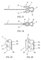
- the clamping strips 23 and 34 of the male teeth elements 2 and the female teeth elements 3 each have a plurality of spurs 24 or 35 at an inner side for engaging into the zipper tapes 1 to affix the male teeth elements 2 and the female teeth elements 3 to the associating zipper tapes 1 (see FIGS. 15 ⁇ 18 ).
- the spurts 24 of the two clamping strips 23 of each male teeth element 2 are arranged in a staggered manner.
- the spurts 35 of the two clamping strips 34 of each female teeth element 3 are also arranged in a staggered manner.
- the male teeth elements 2 and the female teeth elements 3 eliminate the aforesaid clamping strips 23 and 34, and the split tube-like bases 22 and 33 each have a plurality of spurs 24a or 35a for engaging into the zipper tapes 1 to affix the male teeth elements 2 and the female teeth elements 3 to the associating zipper tapes 1 (see FIGS. 21 ⁇ 24 ).
Landscapes
- Slide Fasteners (AREA)
Priority Applications (1)
| Application Number | Priority Date | Filing Date | Title |
|---|---|---|---|
| EP07254217A EP2052639A1 (de) | 2007-10-24 | 2007-10-24 | Reißverschluss |
Applications Claiming Priority (1)
| Application Number | Priority Date | Filing Date | Title |
|---|---|---|---|
| EP07254217A EP2052639A1 (de) | 2007-10-24 | 2007-10-24 | Reißverschluss |
Publications (1)
| Publication Number | Publication Date |
|---|---|
| EP2052639A1 true EP2052639A1 (de) | 2009-04-29 |
Family
ID=39273265
Family Applications (1)
| Application Number | Title | Priority Date | Filing Date |
|---|---|---|---|
| EP07254217A Withdrawn EP2052639A1 (de) | 2007-10-24 | 2007-10-24 | Reißverschluss |
Country Status (1)
| Country | Link |
|---|---|
| EP (1) | EP2052639A1 (de) |
Cited By (2)
| Publication number | Priority date | Publication date | Assignee | Title |
|---|---|---|---|---|
| WO2017084552A1 (zh) * | 2015-11-17 | 2017-05-26 | 吴弘纳 | 一种拉链链齿、拉头及具有该链齿与拉头的拉链 |
| CN114532672A (zh) * | 2022-04-02 | 2022-05-27 | 温州日成拉链有限公司 | 一种可降解注塑拉链及其制备方法 |
Citations (9)
| Publication number | Priority date | Publication date | Assignee | Title |
|---|---|---|---|---|
| US624927A (en) | 1899-05-16 | Elias gunnell | ||
| US1746565A (en) * | 1926-09-22 | 1930-02-11 | Hookless Fastener Co | Separable fastener |
| US1934084A (en) | 1930-08-22 | 1933-11-07 | Hookless Fastener Co | Separable fastener |
| US2991528A (en) * | 1959-03-03 | 1961-07-11 | Irving Constant | Metal slide fasteners and method of making same |
| US3872551A (en) | 1973-07-06 | 1975-03-25 | Textron Inc | Slide fastener having separating end stop |
| US4099301A (en) | 1975-11-22 | 1978-07-11 | Yoshida Kogyo K.K. | Slide fastener combination |
| US6243927B1 (en) * | 1998-04-28 | 2001-06-12 | Ykk Corporation | Slide fastener |
| US6588072B1 (en) | 2001-12-31 | 2003-07-08 | Yu-Pau Lin | Zipper slide |
| US7036191B2 (en) | 2003-04-21 | 2006-05-02 | Chang-Wen Tsaur | Lower stop of zipper |
-
2007
- 2007-10-24 EP EP07254217A patent/EP2052639A1/de not_active Withdrawn
Patent Citations (9)
| Publication number | Priority date | Publication date | Assignee | Title |
|---|---|---|---|---|
| US624927A (en) | 1899-05-16 | Elias gunnell | ||
| US1746565A (en) * | 1926-09-22 | 1930-02-11 | Hookless Fastener Co | Separable fastener |
| US1934084A (en) | 1930-08-22 | 1933-11-07 | Hookless Fastener Co | Separable fastener |
| US2991528A (en) * | 1959-03-03 | 1961-07-11 | Irving Constant | Metal slide fasteners and method of making same |
| US3872551A (en) | 1973-07-06 | 1975-03-25 | Textron Inc | Slide fastener having separating end stop |
| US4099301A (en) | 1975-11-22 | 1978-07-11 | Yoshida Kogyo K.K. | Slide fastener combination |
| US6243927B1 (en) * | 1998-04-28 | 2001-06-12 | Ykk Corporation | Slide fastener |
| US6588072B1 (en) | 2001-12-31 | 2003-07-08 | Yu-Pau Lin | Zipper slide |
| US7036191B2 (en) | 2003-04-21 | 2006-05-02 | Chang-Wen Tsaur | Lower stop of zipper |
Cited By (2)
| Publication number | Priority date | Publication date | Assignee | Title |
|---|---|---|---|---|
| WO2017084552A1 (zh) * | 2015-11-17 | 2017-05-26 | 吴弘纳 | 一种拉链链齿、拉头及具有该链齿与拉头的拉链 |
| CN114532672A (zh) * | 2022-04-02 | 2022-05-27 | 温州日成拉链有限公司 | 一种可降解注塑拉链及其制备方法 |
Similar Documents
| Publication | Publication Date | Title |
|---|---|---|
| US20090113676A1 (en) | Zipper | |
| EP1201144B1 (de) | Schieber für luft- und wasserdichten Reissverschluss | |
| TWI457087B (zh) | Offset buckle | |
| JP4731509B2 (ja) | スライドファスナー用務歯及びスライドファスナー | |
| US7698790B2 (en) | Stop for slide fasteners | |
| TWI376211B (de) | ||
| TW201212840A (en) | Slider for slide fasteners with attached automatic stopping device | |
| US20090265899A1 (en) | Pull-tab for zipper | |
| JP6027653B2 (ja) | 開端スライドファスナーのためのシーリング | |
| CA1282941C (en) | Fluid-tight slide fastener | |
| US20020116798A1 (en) | Upper stopper device for slide fastener | |
| JPWO2010041303A1 (ja) | スライドファスナー | |
| EP2904922A2 (de) | Reißverschluss | |
| CN109843110B (zh) | 拉链组装体 | |
| JP5247823B2 (ja) | 開離嵌挿具付スライドファスナー | |
| JPS5932329Y2 (ja) | 開離嵌插具付きスライドフアスナ− | |
| EP0745338A2 (de) | Automatisch verriegelbarer Schieber für Reissverschluss | |
| KR20070090787A (ko) | 슬라이드 패스너 | |
| EP2052639A1 (de) | Reißverschluss | |
| EP1430804B1 (de) | Verdeckter Reissverschluss | |
| EP1295542A2 (de) | Schieber für Reissverschluss | |
| US4651388A (en) | Sliding clasp fastener | |
| CN102188081B (zh) | 固定拉片式拉链头 | |
| EP0248290B1 (de) | Seilklemme | |
| CA1091903A (en) | Slide fastener |
Legal Events
| Date | Code | Title | Description |
|---|---|---|---|
| PUAI | Public reference made under article 153(3) epc to a published international application that has entered the european phase |
Free format text: ORIGINAL CODE: 0009012 |
|
| AK | Designated contracting states |
Kind code of ref document: A1 Designated state(s): AT BE BG CH CY CZ DE DK EE ES FI FR GB GR HU IE IS IT LI LT LU LV MC MT NL PL PT RO SE SI SK TR |
|
| AX | Request for extension of the european patent |
Extension state: AL BA HR MK RS |
|
| 17P | Request for examination filed |
Effective date: 20090929 |
|
| 17Q | First examination report despatched |
Effective date: 20091023 |
|
| AKX | Designation fees paid |
Designated state(s): AT BE BG CH CY CZ DE DK EE ES FI FR GB GR HU IE IS IT LI LT LU LV MC MT NL PL PT RO SE SI SK TR |
|
| STAA | Information on the status of an ep patent application or granted ep patent |
Free format text: STATUS: THE APPLICATION IS DEEMED TO BE WITHDRAWN |
|
| 18D | Application deemed to be withdrawn |
Effective date: 20120501 |