EP2060947A1 - Dispositif d'affichage à cristaux liquides - Google Patents
Dispositif d'affichage à cristaux liquides Download PDFInfo
- Publication number
- EP2060947A1 EP2060947A1 EP07768188A EP07768188A EP2060947A1 EP 2060947 A1 EP2060947 A1 EP 2060947A1 EP 07768188 A EP07768188 A EP 07768188A EP 07768188 A EP07768188 A EP 07768188A EP 2060947 A1 EP2060947 A1 EP 2060947A1
- Authority
- EP
- European Patent Office
- Prior art keywords
- liquid crystal
- plate
- retardation
- crystal panel
- display device
- Prior art date
- Legal status (The legal status is an assumption and is not a legal conclusion. Google has not performed a legal analysis and makes no representation as to the accuracy of the status listed.)
- Withdrawn
Links
Images


Classifications
-
- G—PHYSICS
- G02—OPTICS
- G02F—OPTICAL DEVICES OR ARRANGEMENTS FOR THE CONTROL OF LIGHT BY MODIFICATION OF THE OPTICAL PROPERTIES OF THE MEDIA OF THE ELEMENTS INVOLVED THEREIN; NON-LINEAR OPTICS; FREQUENCY-CHANGING OF LIGHT; OPTICAL LOGIC ELEMENTS; OPTICAL ANALOGUE/DIGITAL CONVERTERS
- G02F1/00—Devices or arrangements for the control of the intensity, colour, phase, polarisation or direction of light arriving from an independent light source, e.g. switching, gating or modulating; Non-linear optics
- G02F1/01—Devices or arrangements for the control of the intensity, colour, phase, polarisation or direction of light arriving from an independent light source, e.g. switching, gating or modulating; Non-linear optics for the control of the intensity, phase, polarisation or colour
- G02F1/13—Devices or arrangements for the control of the intensity, colour, phase, polarisation or direction of light arriving from an independent light source, e.g. switching, gating or modulating; Non-linear optics for the control of the intensity, phase, polarisation or colour based on liquid crystals, e.g. single liquid crystal display cells
- G02F1/133—Constructional arrangements; Operation of liquid crystal cells; Circuit arrangements
- G02F1/1333—Constructional arrangements; Manufacturing methods
- G02F1/1335—Structural association of cells with optical devices, e.g. polarisers or reflectors
- G02F1/13363—Birefringent elements, e.g. for optical compensation
- G02F1/133634—Birefringent elements, e.g. for optical compensation the refractive index Nz perpendicular to the element surface being different from in-plane refractive indices Nx and Ny, e.g. biaxial or with normal optical axis
-
- G—PHYSICS
- G02—OPTICS
- G02F—OPTICAL DEVICES OR ARRANGEMENTS FOR THE CONTROL OF LIGHT BY MODIFICATION OF THE OPTICAL PROPERTIES OF THE MEDIA OF THE ELEMENTS INVOLVED THEREIN; NON-LINEAR OPTICS; FREQUENCY-CHANGING OF LIGHT; OPTICAL LOGIC ELEMENTS; OPTICAL ANALOGUE/DIGITAL CONVERTERS
- G02F1/00—Devices or arrangements for the control of the intensity, colour, phase, polarisation or direction of light arriving from an independent light source, e.g. switching, gating or modulating; Non-linear optics
- G02F1/01—Devices or arrangements for the control of the intensity, colour, phase, polarisation or direction of light arriving from an independent light source, e.g. switching, gating or modulating; Non-linear optics for the control of the intensity, phase, polarisation or colour
- G02F1/13—Devices or arrangements for the control of the intensity, colour, phase, polarisation or direction of light arriving from an independent light source, e.g. switching, gating or modulating; Non-linear optics for the control of the intensity, phase, polarisation or colour based on liquid crystals, e.g. single liquid crystal display cells
- G02F1/133—Constructional arrangements; Operation of liquid crystal cells; Circuit arrangements
- G02F1/1333—Constructional arrangements; Manufacturing methods
- G02F1/1335—Structural association of cells with optical devices, e.g. polarisers or reflectors
- G02F1/13363—Birefringent elements, e.g. for optical compensation
-
- G—PHYSICS
- G02—OPTICS
- G02F—OPTICAL DEVICES OR ARRANGEMENTS FOR THE CONTROL OF LIGHT BY MODIFICATION OF THE OPTICAL PROPERTIES OF THE MEDIA OF THE ELEMENTS INVOLVED THEREIN; NON-LINEAR OPTICS; FREQUENCY-CHANGING OF LIGHT; OPTICAL LOGIC ELEMENTS; OPTICAL ANALOGUE/DIGITAL CONVERTERS
- G02F1/00—Devices or arrangements for the control of the intensity, colour, phase, polarisation or direction of light arriving from an independent light source, e.g. switching, gating or modulating; Non-linear optics
- G02F1/01—Devices or arrangements for the control of the intensity, colour, phase, polarisation or direction of light arriving from an independent light source, e.g. switching, gating or modulating; Non-linear optics for the control of the intensity, phase, polarisation or colour
- G02F1/13—Devices or arrangements for the control of the intensity, colour, phase, polarisation or direction of light arriving from an independent light source, e.g. switching, gating or modulating; Non-linear optics for the control of the intensity, phase, polarisation or colour based on liquid crystals, e.g. single liquid crystal display cells
- G02F1/133—Constructional arrangements; Operation of liquid crystal cells; Circuit arrangements
- G02F1/1333—Constructional arrangements; Manufacturing methods
- G02F1/1335—Structural association of cells with optical devices, e.g. polarisers or reflectors
- G02F1/133528—Polarisers
-
- G—PHYSICS
- G02—OPTICS
- G02F—OPTICAL DEVICES OR ARRANGEMENTS FOR THE CONTROL OF LIGHT BY MODIFICATION OF THE OPTICAL PROPERTIES OF THE MEDIA OF THE ELEMENTS INVOLVED THEREIN; NON-LINEAR OPTICS; FREQUENCY-CHANGING OF LIGHT; OPTICAL LOGIC ELEMENTS; OPTICAL ANALOGUE/DIGITAL CONVERTERS
- G02F1/00—Devices or arrangements for the control of the intensity, colour, phase, polarisation or direction of light arriving from an independent light source, e.g. switching, gating or modulating; Non-linear optics
- G02F1/01—Devices or arrangements for the control of the intensity, colour, phase, polarisation or direction of light arriving from an independent light source, e.g. switching, gating or modulating; Non-linear optics for the control of the intensity, phase, polarisation or colour
- G02F1/13—Devices or arrangements for the control of the intensity, colour, phase, polarisation or direction of light arriving from an independent light source, e.g. switching, gating or modulating; Non-linear optics for the control of the intensity, phase, polarisation or colour based on liquid crystals, e.g. single liquid crystal display cells
- G02F1/133—Constructional arrangements; Operation of liquid crystal cells; Circuit arrangements
- G02F1/1333—Constructional arrangements; Manufacturing methods
- G02F1/1335—Structural association of cells with optical devices, e.g. polarisers or reflectors
- G02F1/133553—Reflecting elements
-
- G—PHYSICS
- G02—OPTICS
- G02F—OPTICAL DEVICES OR ARRANGEMENTS FOR THE CONTROL OF LIGHT BY MODIFICATION OF THE OPTICAL PROPERTIES OF THE MEDIA OF THE ELEMENTS INVOLVED THEREIN; NON-LINEAR OPTICS; FREQUENCY-CHANGING OF LIGHT; OPTICAL LOGIC ELEMENTS; OPTICAL ANALOGUE/DIGITAL CONVERTERS
- G02F1/00—Devices or arrangements for the control of the intensity, colour, phase, polarisation or direction of light arriving from an independent light source, e.g. switching, gating or modulating; Non-linear optics
- G02F1/01—Devices or arrangements for the control of the intensity, colour, phase, polarisation or direction of light arriving from an independent light source, e.g. switching, gating or modulating; Non-linear optics for the control of the intensity, phase, polarisation or colour
- G02F1/13—Devices or arrangements for the control of the intensity, colour, phase, polarisation or direction of light arriving from an independent light source, e.g. switching, gating or modulating; Non-linear optics for the control of the intensity, phase, polarisation or colour based on liquid crystals, e.g. single liquid crystal display cells
- G02F1/133—Constructional arrangements; Operation of liquid crystal cells; Circuit arrangements
- G02F1/1333—Constructional arrangements; Manufacturing methods
- G02F1/1335—Structural association of cells with optical devices, e.g. polarisers or reflectors
- G02F1/13363—Birefringent elements, e.g. for optical compensation
- G02F1/133638—Waveplates, i.e. plates with a retardation value of lambda/n
Definitions
- the present invention relates to a liquid crystal display device for controlling a viewing angle of a display panel.
- display devices are required to have as wide a viewing angle as possible so that a clear image can be viewed from all viewing angles.
- liquid crystal display devices which have been in widespread use, liquid crystal itself has a viewing angle dependency. On this account, in particular, various technological developments have been promoted for making the viewing angle wider.
- a display device it is favorable for a display device to have a narrow viewing angle so that only a user can view display contents.
- An electronic device such as a laptop type personal computer, a portable information terminal (PDA: Personal Digital Assistant), or a portable phone, in particular, is more likely to be used in a place (e.g., in a train, airplane, etc.) where general public can be present.
- PDA Personal Digital Assistant
- a viewing angle of a display device be narrow because the user does not wish the display contents to be viewed by others near to the user, in view of preservation of confidentiality and/or privacy protection.
- the demand has been recently increased for a liquid crystal display device in which the viewing angle can be switched between a wide viewing angle and a narrow viewing angle in accordance with a situation in which the liquid crystal display device is used.
- Such demand is not limited to liquid crystal display devices. Instead, it is a problem shared by any display devices.
- Patent Document 1 proposes the following technique, in order to meet such a demand.
- the Patent Document 1 discloses a technique in which a retardation control device is provided in addition to a display device for displaying an image.
- a voltage to be applied to the retardation control device is controlled so that a display device has a change in a viewing angle feature.
- the Patent Document 1 adopts a liquid crystal display device, serving as the retardation control device, whose liquid crystal is chiral nematic liquid crystal, homogeneous liquid crystal, or randomly aligned nematic liquid crystal, for example.
- the Patent Document 1 describes that it is possible to switch the viewing angle between a wide viewing angle and a narrow viewing angle by using the liquid crystal display device for controlling retardation. However, the switching of the viewing angle between the wide viewing angle and the narrow viewing angle is not always necessary.
- the display device In a case where the viewing angle can be switched between the wide and the narrow viewing angles in a display device, the display device has a complex arrangement. As such, in view of cost reduction, a display device has been demanded in which viewing angles can be narrowed though not being able to be switched between the wide and narrow viewing angles.
- Patent Document 2 discloses a technique in which a viewing angle is narrowed without being switched between the wide and narrow viewing angles.
- the Patent Document 2 discloses a viewing field control sheet, which substitutes for the retardation control device capable of switching the viewing angle between the wide and narrow viewing angles.
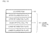
- a louvered film 102 serving as the viewing field control sheet is stacked on top of a liquid crystal panel 101 that has a liquid crystal cell 111 made of TN liquid crystal.
- the louvered film 102 includes (i) base material sections 121 made of a light transmission material and (ii) light absorption barriers 122 made of a light absorption material and formed in a louvered manner.
- the light absorption barriers 122 made of the light absorption material, have a refraction index smaller than that of the base material sections 121 made of light transmission material.
- the louvered film 102 blocks outgoing of light that has an incident angle of a particular angle or more. Thus, it is possible to realize the viewing field control sheet that brings about a peek prevention effect.
- the louvered film 102 disclosed in the Patent Document 2 has recently become a mainstream in viewing angle control panels that does not switch a viewing angle between the wide viewing and narrow viewing angles.
- louvered film disclosed in the Patent Document 2 causes a problem that, when visibility limitation is carried out in diagonal directions, it is not possible to arbitrarily set a direction in which the visibility of the liquid crystal panel should be limited.
- the present invention is made in view of the problem, and an object of the present invention is to provide a liquid crystal display device in which a viewing angle can be narrowed by freely setting, in a reflective liquid crystal panel, a direction in which the visibility limitation should be carried out.
- a liquid crystal display device of the present invention includes: a reflective liquid crystal panel including a liquid crystal panel polarization plate; a polarization plate provided on a light incident side of the liquid crystal panel, with respect to the liquid crystal panel polarization plate; and a retardation member provided between the liquid crystal panel polarization plate and the polarization plate, a retardation of the retardation member in a light path, which light path is occurred when the liquid crystal panel is viewed in a direction at a particular polar angle ⁇ k (0° ⁇ k ⁇ 90°), being set so as to determine a direction in which a visibility limitation should be carried out.
- the retardation member is provided between the liquid crystal panel polarization plate and the polarization plate.
- the retardation is set so that the direction in which the visibility limitation should be carried out is determined.
- Linearly polarized light which has passed through the polarization plate provided on the light incident side of the liquid crystal panel, enters the liquid crystal panel via the retardation member and the liquid crystal panel polarization plate, and is then reflected in the liquid crystal panel.
- the linearly polarized light thus reflected passes through the liquid crystal panel polarization plate and the retardation member again, and enters the polarization plate on the light incident side of the liquid crystal panel again.
- the retardation member functions to prevent the light having returned to the polarization plate from being gone out from there.
- an amount of the light directed from the polarization plate on the light incident side to the viewer can be significantly reduced.
- the linearly polarized light diagonally enters, at a particular polar angle of ⁇ k, the retardation member via the polarization plate on the light incident side. Then, the linearly polarized light is converted into circularly polarized light by the retardation member, and enters the liquid crystal panel polarization plate.
- the liquid crystal panel polarization plate generates linearly polarized light having a light amount which is less by 1 / 2 than that of the circularly polarized light.
- light reflected in the liquid crystal panel returns to the liquid crystal panel polarization plate. This causes the light to be converted into linearly polarized light by the liquid crystal polarization plate, and causes the linearly polarized light to enter the retardation member.
- the linearly polarized light having entered the retardation member is converted into circularly polarized light by the retardation member, and then returns to the polarization plate on the light incident side.
- the polarization plate on the light incident side converts the circularly polarized light into linearly polarized light.
- the linearly polarized light is then directed toward the viewer, which linearly polarized light is caused by the polarization plate on the light incident side to have a light amount of less by 1 / 2 than that of the circularly polarized light.
- the present invention is not limited to the arrangement in which the retardation member causes the phase difference of ⁇ /4.
- the present invention can include an arrangement in which an absorption axis of a liquid crystal polarization plate and that of a polarization plate on a light incident side are parallel to each other (i.e, the above absorption axes are arranged in parallel Nicols).
- retardation may be set so that, with respect to one way of a light path occurred when the liquid crystal display panel is viewed in a direction at a particular polar angle ⁇ k, the retardation member causes a phase difference of ⁇ /2.
- the retardation member rotates, by 90°, a polarized wave surface of linearly polarized light entering the retardation member via the polarization plate on the light incident side at the particular polar angle ⁇ k.
- the linearly polarized light having entered the retardation member cannot pass through the absorption axis of the liquid crystal panel polarization plate, thereby not being able to enter the liquid crystal panel. According to such an effect, it is equally possible to carry out the viewing limitation.
- the present invention can include an arrangement in which an absorption axis of the liquid crystal panel polarization plate and that of the polarization plate on the light incident side are orthogonal to each other (the above absorption axes are arranged in cross Nicols).
- retardation may be set so that, with respect to one way of a light path occurred when the liquid crystal display panel is viewed in a direction at a particular polar angle ⁇ k, the retardation member causes a phase difference of ⁇ /4. This brings about the same effect as described above. As such, it is possible to carry out the visibility limitation.
- retardation of the retardation member as follows with respect to the normal direction of the liquid crystal panel, in order that the visibility in the front direction of the viewer is secured. That is, it is preferable to set the retardation so that, while linearly polarized light having vertically entered the polarization plate on the light incident side is passing through the retardation member, the retardation member rotates, by 90°, a polarized wave surface of the linearly polarized light. The linearly polarized light then passes through the liquid crystal panel polarization plate, and enters the liquid crystal panel. In this case, there is no visibility limitation in the front direction of the viewer.
- the retardation of the retardation member is set so that the visibility limitation is carried out with respect to the direction at the particular polar angle ⁇ k.
- a display on the liquid crystal panel cannot be viewed in the direction at the particular polar angle ⁇ k. It is therefore possible to narrow the viewing angle.
- the direction in which the visibility limitation should be carried out can be set freely in accordance with the free designing of the retardation of the retardation member.
- the liquid crystal display device in which the viewing angle can be narrowed by freely setting, in the reflective liquid crystal panel, a direction in which the visibility limitation should be carried out.
- the absorption axes of the polarization plate and the liquid crystal panel polarization plate be parallel to an x-y plane correlative to the main refraction indexes nx and ny of the first retardation plate.
- the retardation member has optical anisotropy with respect to light that travels along a direction at a particular polar angle ⁇ k (0° ⁇ k ⁇ 90°). As such, it is possible to carry out the visibility limitation in accordance with the designing of the retardation, as described above.
- the main refraction indexes appear to be a spheroid having a humilis shape in its height direction.
- the main refraction indexes appear to be a spheroid looking like an egg standing on end.
- a thickness of the first retardation plate and (ii) a ratio between the main refraction indexes nx (or ny) and nz of the first retardation plate should be set such that, when the liquid crystal panel is viewed in the direction at the particular polar angle ⁇ k, a phase difference of ⁇ /2 is generated in a light path via which light entering the first retardation plate is reflected by the liquid crystal panel, passes through the first retardation plate again, and is gone out from the first retardation plate.
- the polarization plate have the absorption axis parallel to that of the liquid crystal panel polarization plate.
- the retardation member gives, with respect to linearly polarized light passing through the transmission axis of the polarization plate orthogonal to the absorption axis of the polarization plate, a phase difference of approximately ⁇ /2 in a light path via which the linearly polarized light enters and goes out from the retardation member, the circularly polarized light is returned to the polarization plate, as described above. This allows the visibility limitation to be carried out.
- the retardation member gives the phase difference of approximately ⁇ /2 to the linearly polarized light in one way of the light path via which the linearly polarized light enters and goes out from the retardation member
- the retardation member rotates, by 90°, the polarized wave surface of the light, as described above. Then, the linearly polarized light passes through the transmission axis of the liquid crystal panel polarization plate, thereby being able to enter the liquid crystal panel.
- the retardation member rotates, by 90°, the polarized wave surface of the light, as described above. Then, the linearly polarized light passes through the transmission axis of the liquid crystal panel polarization plate, thereby being able to enter the liquid crystal panel.
- the retardation to which the retardations of the first retardation plate and the ⁇ /2 plate amount, is set so that the phase difference as described earlier is caused. This equally allows the visibility limitation to be carried out in the light path occurred when the liquid crystal device is viewed in the direction at the particular polar angle ⁇ k.
- the first retardation plate be made up of a plurality of retardation plates.
- the plurality of the retardation plates, constituting the first retardation plate cause a phase difference of ⁇ /4 in their entirety with respect to one way of a light path occurred when the liquid crystal panel is viewed in a direction at a set single constant polar angle ⁇ k (0° ⁇ k ⁇ 90°).
- the liquid crystal display device of the present invention it is preferable that (i) constant polar angles ⁇ k (0° ⁇ k ⁇ 90°), which are different from each other, be set to the plurality of the retardation plates constituting the first retardation plate, respectively, and (ii) the retardation plates cause phase differences of ⁇ /4, respectively, with respect to one ways of light paths occurred when the liquid crystal panel is viewed in directions at the polar angles ⁇ k (0° ⁇ k ⁇ 90°).
- the first retardation plate made up of the plurality of the retardation plates As such, it is possible to bring about two types of effects by the first retardation plate made up of the plurality of the retardation plates.
- One of the two types of the effects is that it is possible to set a phase difference so that the plurality of the retardation plates can have the phase difference of ⁇ /4 in their entirety with respect to one way of a light path occurred when the liquid crystal panel is viewed in a direction at a set single constant polar angle ⁇ k (0° ⁇ k ⁇ 90°).
- This allows the plurality of retardation plates to cause the phase difference of ⁇ /4 in their entirety in one way of the light path, in a case where a single retardation plate alone cannot cause such a phase difference of ⁇ /4 in one way of the light path occurred when the liquid crystal panel is viewed in the direction at the constant polar angle ⁇ k (0° ⁇ k ⁇ 90°).
- the other one of the two types of the effects is that it is possible to (i) set constant polar angles ⁇ k (0° ⁇ k ⁇ 90°), which are different from each other, for a plurality of retardation plates, respectively, and (ii) set phase differences so that the retardation plates have their phase differences of ⁇ /4, respectively, with respect to one ways of light paths occurred when the liquid crystal panel is viewed in directions at the set polar angles ⁇ k.
- This allows the visibility limitation to be carried out with respect to the plurality of the polar angles ⁇ k.
- the main refraction indexes appear to be an spheroid looking like an egg standing on end.
- ⁇ k a set polar angle
- a phase difference in one way of a light path is equal to ⁇ /4 when the liquid crystal panel is viewed in a direction at the set polar angle ⁇ k (0° ⁇ k ⁇ 90°).
- the phase differences of ⁇ /4 occurred on approach and return routes of the light path amount to ⁇ /2.
- the visibility is limited when the liquid crystal panel is viewed diagonally, i.e., when the liquid crystal panel is viewed in the direction at the set polar angle ⁇ k (0° ⁇ k ⁇ 90°).
- a thickness of the second retardation plate and (ii) a ratio between the main refraction indexes nx (or ny) and nz of the second retardation plate should be set such that, when the liquid crystal panel is viewed at the particular polar angle ⁇ k, a phase difference of ⁇ /2 is generated in a light path via which light entering the second retardation plate is reflected in the liquid crystal panel, passes through the second retardation plate again, and is gone out from the second retardation plate.
- the second retardation plate be made up of a plurality of retardation plates.
- a plurality of retardation plates, constituting the second retardation plate cause a phase difference of ⁇ /4 in their entirety with respect to one way of a light path occurred when the liquid crystal panel is viewed in a direction at a set single constant polar angle ⁇ k (0° ⁇ k ⁇ 90°).
- the liquid crystal display device of the present invention it is preferable that (i) constant polar angles ⁇ k (0° ⁇ k ⁇ 90°), which are different from each other, be set to a plurality of retardation plates constituting the second retardation plate, respectively, and (ii) the retardation plates cause phase differences of ⁇ /4, respectively, with respect to one ways of light paths occurred when the liquid crystal panel is viewed in directions at the polar angles ⁇ k (0° ⁇ k ⁇ 90°).
- the second retardation plate made up of the plurality of the retardation plates As such, it is possible to bring about two types of effects by the second retardation plate made up of the plurality of the retardation plates.
- One of the two types of the effects is that it is possible to set a phase difference so that the plurality of the retardation plates can have a phase difference of ⁇ /4 in their entirety with respect to one way of a light path occurred when the liquid crystal panel is viewed in a direction at a set single constant polar angle ⁇ k (0° ⁇ k ⁇ 90°).
- This allows the plurality of retardation plates to cause the phase difference of ⁇ /4 in their entirety with respect to one way of the light path, in a case where a single retardation plate alone cannot cause such a phase difference of ⁇ /4 with respect to one way of the light path when the liquid crystal panel is viewed in the direction at the constant polar angle ⁇ k (0° ⁇ k ⁇ 90°).
- the other one of the two types of the effects is that it is possible to (i) set constant polar angles ⁇ k (0° ⁇ k ⁇ 90°), which are different from each other, for a plurality of retardation plates, respectively, and (ii) set phase differences so that the retardation plates have their phase differences of ⁇ /4, respectively, with respect to one ways of light paths occurred when the liquid crystal panel is viewed in directions at the set polar angles ⁇ k.
- This allows the visibility limitation to be carried out with respect to the plurality of the polar angles ⁇ k.
- any plate that meets the above requirements can be used as the third plate.
- the third retardation plate be made up of a plurality of retardation plates.
- a plurality of retardation plates, constituting the third retardation plate cause a phase difference of ⁇ /4, in their entirety, with respect to one way of a light path occurred when the liquid crystal panel is viewed in a direction at a set single constant polar angle ⁇ k (0° ⁇ k ⁇ 90°).
- the liquid crystal display device of the present invention it is preferable that (i) constant polar angles ⁇ k (0° ⁇ k ⁇ 90°), which are different from each other, be set to a plurality of retardation plates constituting the third retardation plate, respectively, and (ii) the retardation plates cause phase differences of ⁇ /4, respectively, with respect to one ways of light paths occurred when the liquid crystal panel is viewed in directions at the polar angles ⁇ k.
- One of the two types of the effects is that it is possible to set a phase difference so that the plurality of the retardation plates can have a phase difference of ⁇ /4 in their entirety in one way of light path occurred when the liquid crystal panel is viewed in a direction at a set single constant polar angle ⁇ k (0° ⁇ k ⁇ 90°).
- This allows the plurality of retardation plates to cause the phase difference of ⁇ /4 in their entirety with respect to one way of the light path, in a case where a single retardation plate alone cannot cause such a phase difference of ⁇ /4 with respect to one way of the light path occurred when the liquid crystal panel is viewed in the direction at the constant polar angle ⁇ k (0° ⁇ k ⁇ 90°).
- the other one of the two types of the effects is that it is possible to (i) set constant polar angles ⁇ k (0° ⁇ k ⁇ 90°), which are different from each other, for the retardation plates, respectively, and (ii) set phase differences so that the retardation plates have their phase differences of ⁇ /4, respectively, in one ways of light paths occurred when the liquid crystal panel is viewed in directions at the polar angles ⁇ k.
- This allows the visibility limitation to be carried out with respect to the plurality of the polar angles ⁇ k.
- a liquid crystal display device of the present invention can include any component member that is not shown in the drawings referred in the present description. Besides, dimensions of the members in the drawings do not accurately represent actual dimensions of the constituting members or their dimensional ratios.
- Fig. 1 is a cross-sectional view for schematically showing the arrangement of the liquid crystal display device 30.
- the liquid crystal display device 30 is a reflective liquid crystal display device. As shown in Fig. 1 , the liquid crystal display device 30 includes a liquid crystal panel 20 on which a negative C plate 31 and a polarization plate 32 are stacked in this order.
- the negative C plate 31 serves as a retardation member as well as a first retardation plate.
- the liquid crystal panel 20 includes a liquid crystal cell 10, a ⁇ /4 plate 21 for optical compensation, and a liquid crystal panel polarization plate 22.
- a transmission axis of the liquid crystal panel polarization plate 22 is parallel to that of the polarization plate 32.
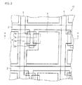
- Fig. 2 is a plan view showing the arrangement of the liquid crystal cell 10.
- Fig. 3 is a cross-sectional view taken on a line X-X in Fig. 2 .
- the liquid crystal cell 10 includes a plurality of gate bus lines 2 made of a material such as chrome (Cr) or tantalum (Ta), on an insulating substrate 1 made of a material such as glass.
- the gate bus lines 2 are provided parallel to each other, and gate electrodes 2a diverge from the gate bus lines 2.
- the gate bus lines 2 serve as scanning lines, respectively.
- a gate insulation film 3 made of a material such as silicon nitride (SiNx) or oxide silicon (SiOx) is formed so as to cover the gate electrodes 2a.
- a semiconductor layer 4a made of a material such as amorphous silicon, polycrystalline silicon, or CdSe is formed.
- contact electrodes 4b made of a material such as amorphous silicon are formed.
- a source electrode 5a made of a material such as titanium, molybdic, or aluminum is provided.
- a drain electrode 5b made of a material such as titanium, molybdic, or aluminum is provided on the other one of the contact electrode 4b.
- the source electrode 5a is connected to a source bus line 5 that serves as a signal line.
- the source bus line 5 intersects with a gate bus line 2 via the gate insulation film 3.
- the source bus line 5 is made of the same metal as the source electrode 5a.
- a TFT 6 is made up of the gate electrode 2a, the gate insulation film 3, the semiconductor layer 4a, the source electrode 5a, and the drain electrode 5b.
- the TFT 6 has a function of a switching element.
- an organic insulation film 7 is formed so as to cover gate bus lines 2, source bus lines 5, and TFTs 6.
- a convex section 7a is provided in a region of the organic insulation film 7 where a reflection electrode 8 is formed.
- the convex section 7a has a taper shape, and its head part has a doughnut-shaped or a circular cross section.
- a contact hole 8a is provided in a region of the organic insulation film 7 where a drain electrode 5b is formed.
- the reflection electrode 8 made of a material such as aluminum (Al) or silver (Ag) is formed.
- the reflection electrode 8 is connected to the drain electrode 5b via a contact hole 8a.
- an alignment film 9 is further formed on the reflection electrodes 8.
- the color filter 12 includes (i) a magenta or green filter 12a in a region where the substrate 11 faces a reflection electrode 8, and (ii) a black filter 12b in a region where the substrate 11 does not face the reflection electrode 8.
- a transparent counter electrode 13 made of a material such as ITO (Indium Tin Oxide) is formed.
- an alignment film 14 is further formed on the counter electrode 13, an alignment film 14 is further formed.
- the substrate 1 and the counter substrate 14 are combined to face each other so that the reflection electrode 8 and the magenta or green filter 12a correspond to each other.
- Liquid crystal 15 is filled in between the substrate 1 and the counter substrate 11.
- the liquid crystal cell 10 Since it is necessary, in the liquid crystal cell 10, for the liquid crystal to be driven by a display unit such as a pixel unit or a segment unit, the liquid crystal cell 10 has an electrode structure corresponding to the display unit.
- the liquid crystal cell 10 of the liquid crystal panel 20 has a display mode of, for example, a VA (Vertical Alignment) mode.
- the liquid crystal cell 10 can have a TN (Twisted Nematic) liquid crystal mode that uses positive nematic liquid crystal having twisted alignment or other display modes.
- the liquid crystal cells 10 can be any liquid crystal cells capable of displaying a character, image, or moving image.
- the liquid crystal cell 10 can be a liquid crystal cell capable of carrying out a color display or a liquid crystal cell for exclusively carrying out a monochrome display.
- Fig. 4 is a cross-sectional view showing an arrangement of the liquid crystal panel 20.
- Fig. 5(a) shows a pathway and a polarization state of outside light that are obtained when no voltage is applied.
- Fig. 5(b) shows a pathway and a polarization state of outside light obtained when a voltage is applied.
- a parallel Nicols configuration is adopted in the reflective liquid crystal panel 20.
- the incident light passes through the single liquid crystal panel polarization plate 22 twice in all, i.e., when it enters the liquid crystal panel polarization plate 22 and when it is reflected by the reflection electrode 8.
- the ⁇ /4 plate 21 is provided between the liquid crystal cell 10 and the liquid crystal panel polarization plate 22 so as to adjust the polarization of the incident light.
- the linearly polarized light when the linearly polarized light enters the ⁇ /4 plate 21 downward via the liquid crystal panel polarization plate 22 while no voltage is applied, the linearly polarized light is converted into, for example, left circularly polarized light by the ⁇ /4 plate 21 (see Fig 5(a) ).
- the left circularly polarized light is reflected by the reflection electrode 8 to become right circularly polarized light.
- a rotational direction of the circularly polarized light is defined as a rotational direction being watched from a light traveling direction side.
- the right circularly polarized light passes through the liquid crystal panel polarization plate 22, again, via the ⁇ /4 plate 21.
- the VA mode liquid crystal molecules tilt.
- the liquid crystal cell 10 converts, into linearly polarized light, the left circularly polarized light passing though the ⁇ /4 plate 21 (see Fig. 5(b) ).
- the linearly polarized light thus converted has a polarized wave surface that is rotated by 90° with respect to a polarized wave surface of linearly polarized light that enters the ⁇ /4 plate 21 via the liquid crystal panel polarization plate 22.
- the linearly polarized light thus converted passes through a liquid crystal layer and the ⁇ /4 plate 21 again, after being reflected by the reflection electrode 8.
- the application of an on-voltage causes the linearly polarized light to be gone out from the liquid crystal panel polarization plate 22, as described above.
- This allows a display on the liquid crystal cell 10 to be viewed in any of top, bottom, right, and left directions, when a display screen of the liquid crystal panel 20 is viewed (see Fig. 6 ).
- X 22 indicates an absorption axis of the liquid crystal panel polarization plate 22.
- a direction in which the display is visible is indicated by "white.”
- the main refraction indexes nx, ny, and nz are refraction indexes in directions of axes x, y, and z that are orthogonal to each other.
- the negative C plate 31 of the present embodiment is further arranged so as to cause a phase difference of ⁇ /4 to be generated between an ordinary light component and an extraordinary light component, when the liquid crystal panel is viewed in a direction at a particular polar angle ⁇ k (described later with reference to Fig. 9 ).
- the particular polar angle ⁇ k is, for example, 15°
- the negative C plate 31 serves as a ⁇ /4 plate with respect to light that travels at the polar angle ⁇ k of 15°.
- outside light diagonally enters, at a particular polar angle of ⁇ k, the polarization plate 32 on the light incident side. Then, the outside light is converted into linearly polarized light by the polarization plate 32, and enters the negative C plate 31. The linearly polarized light thus converted enters the negative C plate 31, and is given a phase difference of ⁇ /4 by the negative C plate 31. This causes the linearly polarized light to be converted into circularly polarized light. The circularly polarized light thus converted enters the polarization plate 22. This causes the liquid crystal panel polarization plate 22 to transmit linearly polarized light having a light amount of less by 1 / 2 than that of the circularly polarized light.
- the above transmittance of the polarization plate is of several tens of percent. As such, the light amount is further decreased. For example, if the polarization plate 32 has a transmittance of 50% with respect to the outside light, a light amount of the light having entered the liquid crystal display device of the present embodiment at the particular polar angle ⁇ k is decreased to 1/4. This allows the visibility limitation to be secured effectively.
- the negative C plate 31 does not affect the visibility limitation in a light path parallel to a direction of a normal line of the polarization plate 32, on the other hand.
- the light amount is reduced due to only the transmittance of the polarization plate 32, which transmittance is obtained when the outside light is converted into the linearly polarized light.
- the polarization plate 32 has a transmittance of 50%
- a light amount of the light having entered the liquid crystal display device of the present embodiment at a polar angle ⁇ k of 0° is decreased to 1/2.
- light having diagonally entered the liquid crystal display device of the present embodiment has a light amount which is decreased to 1/2, as compared to that of light having vertically entered the liquid crystal display device of the present embodiment.
- the negative C plate 31 can be arranged to cause a phase difference of ⁇ /2 when the negative C plate 31 is viewed in a direction at a particular polar angle ⁇ k.
- the negative C plate 31 rotates, by 90°, a polarized wave surface of linearly polarized light incident on the negative C plate 31 via the polarization plate 32.
- the negative C plate 31 directs the linearly polarized light to the liquid crystal panel polarization plate 22.
- the liquid crystal panel polarization plate 22 absorbs the linearly polarized light without transmitting it. As such, no light enters the liquid crystal panel 20. On this account, it is possible to limit the visibility obtained when the liquid crystal panel 20 is viewed in the direction at the particular polar angle ⁇ k.
- the description deals with a case where the visibility in a direction at "a particular polar angle ⁇ k of 15°" is limited. In practice, however, in a case where a phase difference of ⁇ /4 is generated when the liquid crystal panel 20 is viewed at a particular polar angle ⁇ k, the visibility in the particular polar angle ⁇ k ⁇ 10° is limited.
- liquid crystal display device 30 of the present embodiment it is possible to provide a phase difference of ⁇ /4 in a direction at a particular polar angle ⁇ k of the negative C plate 31. As such, it is possible, by changing the designing of the negative C plate 31, to arbitrarily set a direction in which visibility obtained when the liquid crystal panel 20 is diagonally viewed should be limited.
- the direction is set such that, when the liquid crystal panel 20 is diagonally viewed at the particular polar angle ⁇ k, a phase difference of 1/2 is generated in a light path via which light entering the negative C plate 31 is reflected by the reflection electrode 8 in the liquid crystal panel 20, passes through the negative C plate 31 again, and is gone out from the negative C plate 31.
- the length of the light path is determined by thicknesses of the negative C plate 31, the liquid crystal panel polarization plate 22, and the liquid crystal panel 20.
- a thickness of the negative C plate 31 and (ii) a ratio between the main refraction indexes nx (or ny) and nz of the negative C plate 31 are set so that the phase difference of 1/2 is generated.
- a viewing angle is indicated by an azimuth ⁇ and a polar angle ⁇ , with a center of the display surface of the polarization plate 32 being a reference point.
- the viewing angle is defined by the display surface of the liquid crystal panel 20 and a certain viewing point to the polarization plate 32.
- Fig. 9 shows viewing angles of five viewing points P1 through P5 with respect to the polarization plate 32 of the liquid crystal display device 30.
- an azimuth ⁇ is a rotational angle of a line that connects (i) a center 32c of the polarization plate 32 to (ii) a point on a surface of the polarization plate 32 to which point a perpendicular line of a viewing point extends.
- Fig. 9 shows an example in which an azimuth ⁇ increases clockwise from the viewing point P5 that is positioned on the normal line of the polarization plate 32. According to the example in Fig.
- a first viewing point P1 has an azimuth ⁇ 1 of 0°
- a second viewing point P2 has an azimuth ⁇ 2 of 90°
- a third viewing point P3 has an azimuth ⁇ 3 of 180°
- a fourth viewing point P4 has an azimuth ⁇ 4 of 270°.
- a polar angle ⁇ is an angle defined by (i) a line connecting the center 32c of the polarization plate 32 to a viewing point and (ii) the normal line of the polarization plate 32.
- all of the polar angles ⁇ 1 through ⁇ 4 are, for example, 45°.
- a fifth viewing point P5 can be said as a viewing point on a normal line of the liquid crystal panel polarization plate 22.
- the negative C plate 31 gives a phase difference of ⁇ /2, in all, with respect to the polarized light that enters and goes out from the negative C plate 31 in a direction at a particular polar angle ⁇ k, i.e., in a specific diagonal direction. That is, if the linearly polarized light is considered to be constituted by two sine wave components, then the negative C plate 31 has a function of shifting, by a half waveform (180°), a phase of one of the two sine wave components of the linearly polarized light that enters the negative C plate 31.
- a black display is carried out at the viewing point P1 (azimuth of 0°), the viewing point P2 (azimuth of 90°), the viewing point P3 (azimuth of 180°), the viewing point P4 (azimuth of 270°), an azimuth of 45°, and an azimuth of 225° (see Fig. 10 ).
- This allows the visibility to be limited at least in four directions (top, bottom, right and left).
- a white display is carried out at the viewing point P5 (polar angle ⁇ of 0°) located in the front surface direction, an azimuth of 135°, and an azimuth of 305°.
- the black display and the white display refer to display conditions, respectively, that are obtained when a voltage is applied to the liquid crystal cells 10.
- the reason why the white display is carried out at the azimuths of 135° and 305° is that: (i) the absorption axis X 22 of the liquid crystal panel polarization plate 22 and the absorption axis X 32 of the polarization plate 32 are parallel to a slow axis SA of the negative C plate 31 (the absorption axes X 22 and X 32 are parallel to an x-y plane correlative to the main refraction indexes nx and ny of the negative C plate 31) and (ii) the directions of the azimuths of 135° and 305° are parallel to transmission axes of the liquid crystal panel polarization plate 22 and the polarization plate 32.
- the absorption axes X 22 and X 32 of the liquid crystal panel polarization plate 22 and the polarization plate 32 are orthogonal to the transmission axes of the liquid crystal panel polarization plate 22 and the polarization plate 32, respectively.
- the transmission axes of the liquid crystal panel polarization plate 22 and the polarization plate 32 are arranged to be parallel to each other, as described above.
- the transmission axes of the liquid crystal panel polarization plate 22 and the polarization plate 32 are arranged to be substantially parallel to each other, the effect of the visibility limitation can be obtained more, as compared to conventional techniques. As such, it is not requisite in the present invention that the transmission axes are parallel to each other.
- the absorption axis X 22 of the liquid crystal panel polarization plate 22 and the absorption axis X 32 of the polarization plate 32 are rotated by -45° so as to be parallel to a longitudinal direction of the display screen (see Fig. 11(a) ).
- the absorption axis X 22 of the liquid crystal panel polarization plate 22 and the absorption axis X 32 of the polarization plate 32 are rotated by +45° so as to be parallel to the transverse direction of the display screen (see Fig. 11(b) ).
- a retardation plate is not necessarily limited to this arrangement.
- a retardation plate serving as a retardation member and a first retardation plate can be made up of, for example, two retardation plates.
- a retardation plate can be made up of, for example, a first negative C plate 31 a and a second negative C plate 31b. This can bring about the similar effect.
- first negative C plate 31a and the second negative C plate 31b it is possible to provide a liquid crystal display device 30a in which the first negative C plate 31a and the second negative C plate 31b cause a phase difference of ⁇ /4, in their entirety, in a direction at the specific polar angle ⁇ k (see Fig. 12 ).
- a liquid crystal display device 30b in which a first negative C plate 31a, one of two negative C plates, causes a phase difference of ⁇ /4 in a direction at a first specific polar angle ⁇ k1, whereas a second negative C plate 31b, the other one of the two negative C plates, causes a phase difference of ⁇ /4 in a direction at a second specific polar angle ⁇ k2.
- Figs. 12 and 13 exemplify the cases where the two retardation plates, i.e., the first negative C plate 31a and the second negative C plate 31b, are provided.
- the present embodiment is, however, not necessarily limited to this. Instead, a plurality of retardation plates, e.g., 3 or more retardation plates, can be provided.
- the liquid crystal display devices 30, 30a, and 30b of the present embodiment include (i) the negative C plate 31 or (ii) the first negative C plate 31a and the second negative C plate 31b between the liquid crystal panel polarization plate 22 and the polarization plate 32 in the reflective liquid crystal panel 20.
- the negative C plate 31, the first negative C plate 31 a, and the second negative C plate 31b serve as a retardation member for setting a direction in which the visibility limitation should be carried out.
- liquid crystal display devices 30, 30a, and 30b in each of which the viewing angle can be narrowed.
- a direction in which the visibility limitation should be carried out can be set freely in accordance with the designing of the negative C plate. It is therefore possible to narrow the viewing angle.
- the main refraction indexes nx, ny, and nz when the main refraction indexes nx, ny, and nz are subjected to the three-dimensional display, the main refraction indexes appear to be a spheroid having a humilis shape in its height direction.
- ⁇ k (0° ⁇ k ⁇ 90°
- an equal luminance display is carried out except in some azimuths, thereby causing no adverse effect on the display content, such as distortion.
- a phase difference in one way of a light path is equal to ⁇ /4 when the liquid crystal panel 20 is viewed in a direction at the set polar angle ⁇ k (0° ⁇ k ⁇ 90°).
- the phase differences of ⁇ /4 occurred on approach and return routes amount to ⁇ /2.
- the visibility is limited when the liquid crystal panel 20 is viewed diagonally, i.e., when the liquid crystal panel 20 is viewed in the direction at the set polar angle ⁇ k (0° ⁇ k ⁇ 90°).
- the first retardation plate is made up of a plurality of the retardation plates. This brings about two types of effects.
- One of the two types of the effects is that it is possible to set a phase difference so that the plurality of the retardation plates can have a one way phase difference of ⁇ /4 in their entirety when the liquid crystal panel 20 is viewed in a direction at a set single constant polar angle ⁇ k (0° ⁇ k ⁇ 90°).
- a first negative C plate 31a and a second C plate 31b This allows the plurality of negative C plates, i.e., a first negative C plate 31a and a second C plate 31b, to cause the phase difference of ⁇ /4 in their entirety with respect to one way of a light path, in a case where a single retardation plate alone cannot cause such a phase difference of ⁇ /4 with respect to one way of the light path occurred when the liquid crystal panel 20 is viewed in the direction at the constant polar angle ⁇ k (0° ⁇ k ⁇ 90°).
- the other one of the two types of the effects is that it is possible to (i) set constant polar angles ⁇ k (0° ⁇ k ⁇ 90°), which are different from each other, for the first negative C plate 31a and the second negative C plate 31b serving as a retardation plate, respectively, and (ii) set phase differences so that the first negative C plate 31a and the second negative C plate 31b have their phase differences of ⁇ /4, respectively, with respect to one ways of light paths occurred when the liquid crystal panel 20 is viewed in directions at the polar angles ⁇ k.
- a liquid crystal display device 40 of the present embodiment includes a positive C plate 41 (second retardation plate) in place of the negative C plate 31 in the liquid crystal display device 30 of Embodiment 1.
- the main refraction indexes nx, ny, and nz are refraction indexes in axis directions of x, y, and z that are orthogonal to each other.
- the positive C plate 41 of the present embodiment is further arranged to cause a phase difference of ⁇ /4, when a liquid crystal panel 20 is viewed in a direction at a particular polar angle ⁇ k.
- a particular polar angle ⁇ k is, for example, 15°.
- light which enters the reflective liquid crystal panel 20 via a polarization plate 32 and the positive C plate 41 serving as a ⁇ /4 plate, passes through the positive C plate 41 twice in all, i.e., when it enters the positive C plate 41 and when it is reflected by a reflection electrode 8.
- This causes a black display to be made in the direction at the particular polar angle ⁇ k of 15°.
- the positive C plate 41 can make wider a range of polar angles, in which visibility limitation can be carried out.
- the positive C plate 41 is set such that, when the liquid crystal panel 20 is diagonally viewed at a particular polar angle ⁇ k, a phase difference of ⁇ /2 is generated in a light path via which the light entering the positive C plate 41 is reflected by the reflection electrode 8 in the liquid crystal panel 20, passes through the positive C plate 41 again, and is gone out from the positive C plate 41.
- the positive C plate 41 causes the phase difference of ⁇ /2 in the direction at the particular polar angle ⁇ k, i.e., in the specific diagonal direction. That is, if linearly polarized light is considered to be constituted by two sine wave components, then the positive C plate 41 has a function of shifting, by a half waveform (180°), a phase of one of the two sine wave components of the linearly polarized light that has entered the positive C plate 41.
- a black display is carried out at the viewing point P1 (azimuth of 0°), the viewing point P2 (azimuth of 90°), the viewing point P3 (azimuth of 180°), the viewing point P4 (azimuth of 270°), an azimuth of 135°, and an azimuth of 305° (see Fig. 16 ).
- This allows the visibility to be limited in four directions (top, bottom, right and left).
- a white display is carried out at the viewing point P5 (polar angle ⁇ of 0°) located in a front surface direction, an azimuth of 45°, and an azimuth of 225°.
- the black display and the white display refer to display conditions, respectively, that are obtained when a voltage is applied to the liquid crystal cells 10.
- the reason why the white display is carried out at the azimuths of 45° and 225° is that: (i) an absorption axis X 22 of the liquid crystal panel polarization plate 22 and an absorption axis X 32 of the polarization plate 32 are orthogonal to a slow axis SA of the positive C plate 41, and (ii) directions of azimuths of 135° and 305° are parallel to the absorption axes X 22 and X 32 of the liquid crystal panel polarization plate 22 and the polarization plate 32.
- the slow axis SA of the positive C plate 41 is parallel to an axis z.
- the positive C plate is made of a single retardation plate, as shown in Fig. 14 .
- a retardation plate is not necessarily limited to this arrangement.
- the positive C plate 41 can be made up of, for example, two retardation plates. This can bring about the similar effect. It is also possible to make the retardation plate of a plurality of retardation plates, e.g., 3 or more retardation plates.
- the main refraction indexes nx, ny, and nz when the main refraction indexes nx, ny, and nz are subjected to the three-dimensional display, the main refraction indexes appear to be an spheroid looking like an egg standing on end (see Fig. 15(b) ).
- ⁇ k (0° ⁇ k ⁇ 90°
- an equal luminance display is carried out except in some azimuths, thereby causing no adverse effect on the display content, such as distortion.
- phase difference is equal to ⁇ /4 when the liquid crystal panel 20 is viewed in a direction at the set polar angle ⁇ k (0° ⁇ k ⁇ 90°).
- the phase differences of ⁇ /4 occurred on approach and return routes amount to ⁇ /2.
- the visibility is limited when the liquid crystal panel 20 is viewed diagonally, i.e., when the liquid crystal panel 20 is viewed in the direction at the set polar angle ⁇ k (0° ⁇ k ⁇ 90°).
- a thickness of the second retardation plate and (ii) a ratio between the main refraction indexes nx (or ny) and nz of the second retardation plate should be set such that, when the liquid crystal panel 20 is viewed at the particular polar angle ⁇ k, a phase difference of ⁇ /2 is generated in a light path via which light having entered the second retardation plate is reflected by the reflection electrode 8 in the liquid crystal panel 20, passes through the second retardation plate again, and is gone out from the second retardation plate.
- the positive C plate 41 serving as the second retardation plate can be made up of a plurality of retardation plates.
- One of the two types of the effects is that it is possible to set a phase difference so that the plurality of the retardation plates can have a phase difference of ⁇ /4 in their entirety with respect to one way of a light path occurred when the liquid crystal panel 20 is viewed in a direction at a set single constant polar angle ⁇ k (0° ⁇ k ⁇ 90°).
- This allows the plurality of retardation plates to cause the phase difference of ⁇ /4 in their entirety with respect to one way of the light path, in a case where a single retardation plate alone cannot cause such a phase difference of ⁇ /4 with respect to one way of the light path occurred when the liquid crystal panel 20 is viewed in the direction at the constant polar angle ⁇ k (0° ⁇ k ⁇ 90°).
- the other one of the two types of the effects is that it is possible to (i) set constant polar angles ⁇ k (0° ⁇ k ⁇ 90°), which are different from each other, for the retardation plates, respectively, and (ii) set phase differences so that the retardation plates have their phase differences of ⁇ /4, respectively, with respect to one ways of light paths occurred when the liquid crystal panel 20 is viewed in directions at the polar angles ⁇ k. This makes it possible to control the display so that its visibility is limited in a diagonal direction over a wide range.
- the positive A plate, the negative A plate, and the X plate serves as a retardation member and a third retardation plate.
- Each of the third retardation plate is arranged such that any one of axis directions of main refraction indexes nx and ny is parallel to an absorption axis X 32 of a polarization plate 32.
- Each of the third retardation plates further causes a one way phase difference of ⁇ /4 when a liquid crystal panel 20 is viewed in a direction at a set polar angle ⁇ k (0° ⁇ k ⁇ 90°).
- a third retardation plate has main refraction indexes nx and ny that are not equal to each other, no phase difference is generated in a plane parallel to a display surface, provided that the third retardation plate is arranged so that any one of the axis directions of the refraction indexes nx and ny is parallel to the absorption axis X 32 of the polarization plate 32.
- the third retardation plate is arranged so that any one of the axis directions of the refraction indexes nx and ny is parallel to the absorption axis X 32 of the polarization plate 32.
- the X plate satisfies the relation of nx>ny>nz.
- the third retardation plate a plate satisfying a relation of nx>nz>ny (see Fig. 18(d) ) or a plate satisfying a relation of nz>nx>ny (see Fig. 18(e) ) so that any one direction of the axis directions of the refraction indexes nx and ny is parallel to the absorption axis X 32 of the polarization plate 32.
- each of the third retardation plates can be made up of a plurality of retardation plates, as in the cases of Embodiments 1 and 2.
- One of the two types of the effects is that it is possible to set a phase difference so that the plurality of the retardation plates can have a phase difference of ⁇ /4 in their entirety with respect to one way of a light path occurred when the liquid crystal panel 20 is viewed in a direction at a set single constant polar angle ⁇ k (0° ⁇ k ⁇ 90°).
- This allows the plurality of retardation plates to cause the phase difference of ⁇ /4 in their entirety with respect to one way of the light path, in a case where a single retardation plate alone cannot cause such a phase difference of ⁇ /4 with respect to one way of the light path occurred when the liquid crystal panel 20 is viewed in the direction at the constant polar angle ⁇ k (0° ⁇ k ⁇ 90°).
- the other one of the two types of the effects is that it is possible to (i) set single constant polar angles ⁇ k (0° ⁇ k ⁇ 90°), which are different from each other, for the retardation plates, respectively, and (ii) set phase differences so that the retardation plates have their phase differences of ⁇ /4, respectively, with respect to one ways of light paths occurred when the liquid crystal panel 20 is viewed in directions at the polar angles ⁇ k. This makes it possible to control the display so that its visibility is limited in a diagonal direction over a wide range.
- Embodiments 1 through 3 a parallel Nicols configuration is adopted.
- an absorption axis of a polarization plate 32 and that of a liquid crystal panel polarization plate 22 are arranged to be parallel to each other.
- retardation members such as a negative C plate 31 or the like
- an arrangement of the parallel Nicolas can be simplified, as compared to that of a cross Nicolas (later described).
- the visibility limitation as described earlier can be carried out by additionally providing a ⁇ /2 plate.
- Fig. 21 shows an arrangement of a liquid crystal display device of the present invention in which the cross Nicols configuration is adopted.
- a ⁇ /2 plate 33 is provided between a polarization plate 32 and a liquid crystal panel polarization plate 22.
- the ⁇ /2 plate 33 can be provided between the polarization plate 32 and the negative C plate 31 or between the negative C plate 31 and the liquid crystal panel polarization plate 22.
- An exemplary modification of the retardation member described in Embodiments 1 through 3 can also be used in place of the negative C plate 31.
- the ⁇ /2 plate 22 gives a phase difference of ⁇ /2 to linearly polarized light that has passed through the polarization plate 32. This rotates, by 90°, a polarized wave surface of the linearly polarized light. As such, the linearly polarized light is not optically affected by the negative C plate 31, in a light path located in a front direction of a viewer. Thus, the linearly polarized light can pass through, without being absorbed, the liquid crystal panel polarized plate 22, the liquid crystal panel polarized plate 22 and the polarized plate 32 having a relation of the cross Nicols configuration. Thus, there is no visibility limitation in the front direction of the viewer.
- retardation is set so that, with respect to a light path occurred when the liquid crystal display device is viewed in a direction at a particular polar angle ⁇ k, (i) the retardation member such as the negative C plate and (ii) the 1/2 plate 33, in their entirety, function as the retardation member of the present invention that carries out the visibility limitation.
- the retardation member such as the negative C plate and the 1/2 plate 33, in their entirety, function as the retardation member of the present invention that carries out the visibility limitation.
Landscapes
- Physics & Mathematics (AREA)
- Nonlinear Science (AREA)
- Mathematical Physics (AREA)
- Chemical & Material Sciences (AREA)
- Crystallography & Structural Chemistry (AREA)
- General Physics & Mathematics (AREA)
- Optics & Photonics (AREA)
- Liquid Crystal (AREA)
- Polarising Elements (AREA)
Applications Claiming Priority (2)
| Application Number | Priority Date | Filing Date | Title |
|---|---|---|---|
| JP2006243326 | 2006-09-07 | ||
| PCT/JP2007/063439 WO2008029553A1 (fr) | 2006-09-07 | 2007-07-05 | Dispositif d'affichage à cristaux liquides |
Publications (2)
| Publication Number | Publication Date |
|---|---|
| EP2060947A1 true EP2060947A1 (fr) | 2009-05-20 |
| EP2060947A4 EP2060947A4 (fr) | 2009-12-16 |
Family
ID=39156998
Family Applications (1)
| Application Number | Title | Priority Date | Filing Date |
|---|---|---|---|
| EP07768188A Withdrawn EP2060947A4 (fr) | 2006-09-07 | 2007-07-05 | Dispositif d'affichage à cristaux liquides |
Country Status (6)
| Country | Link |
|---|---|
| US (1) | US7932975B2 (fr) |
| EP (1) | EP2060947A4 (fr) |
| JP (1) | JP5043019B2 (fr) |
| KR (1) | KR101051200B1 (fr) |
| CN (1) | CN101479654B (fr) |
| WO (1) | WO2008029553A1 (fr) |
Families Citing this family (16)
| Publication number | Priority date | Publication date | Assignee | Title |
|---|---|---|---|---|
| EP2199848A4 (fr) * | 2007-10-18 | 2011-07-20 | Sharp Kk | Dispositif d'affichage à cristaux liquides |
| JP5546766B2 (ja) * | 2009-01-07 | 2014-07-09 | 日東電工株式会社 | 液晶パネルおよび液晶表示装置 |
| KR102046152B1 (ko) | 2012-11-20 | 2019-11-19 | 삼성디스플레이 주식회사 | 편광판 및 이를 포함하는 액정 표시 장치 |
| KR101983262B1 (ko) | 2012-11-23 | 2019-05-29 | 삼성디스플레이 주식회사 | 액정 표시 패널 및 이를 포함하는 액정 표시 장치 |
| KR101587681B1 (ko) * | 2013-01-22 | 2016-01-21 | 제일모직주식회사 | 편광판 및 이를 포함하는 광학표시장치 |
| CN104658439B (zh) * | 2013-11-19 | 2017-10-27 | 江苏和成显示科技股份有限公司 | 一种3d led显示屏 |
| CN103792742A (zh) * | 2014-01-23 | 2014-05-14 | 京东方科技集团股份有限公司 | 液晶显示器件 |
| KR20150137217A (ko) | 2014-05-28 | 2015-12-09 | 삼성디스플레이 주식회사 | 액정표시장치 |
| KR20160017365A (ko) | 2014-08-05 | 2016-02-16 | 삼성디스플레이 주식회사 | 액정표시장치 |
| CN104536220A (zh) * | 2015-01-27 | 2015-04-22 | 京东方科技集团股份有限公司 | 一种显示装置及其控制方法、专用眼镜和显示系统 |
| CN104730758A (zh) | 2015-04-01 | 2015-06-24 | 合肥京东方光电科技有限公司 | 一种显示面板及显示装置 |
| CN105552105B (zh) * | 2016-01-26 | 2019-04-02 | 京东方科技集团股份有限公司 | 显示装置及其驱动方法、制作方法以及防偷窥显示系统 |
| KR102602158B1 (ko) * | 2016-03-10 | 2023-11-14 | 삼성디스플레이 주식회사 | 광학 필름 및 이를 포함하는 액정표시장치 |
| CN105700247B (zh) | 2016-04-19 | 2020-01-03 | 深圳市华星光电技术有限公司 | 液晶显示装置、量子棒配向板及其制造方法 |
| CN111610666B (zh) * | 2020-06-24 | 2023-10-13 | 京东方科技集团股份有限公司 | 液晶面板及显示装置 |
| JP2023147936A (ja) * | 2022-03-30 | 2023-10-13 | シャープディスプレイテクノロジー株式会社 | 液晶表示装置 |
Family Cites Families (11)
| Publication number | Priority date | Publication date | Assignee | Title |
|---|---|---|---|---|
| JPH10268251A (ja) | 1997-03-27 | 1998-10-09 | Advanced Display:Kk | 液晶表示装置の制御方法 |
| JP3322197B2 (ja) | 1997-12-17 | 2002-09-09 | 松下電器産業株式会社 | 液晶表示装置 |
| US6433845B1 (en) * | 1998-04-10 | 2002-08-13 | Nec Corporation | Reflection type liquid crystal display with particular angle between polarization axis and quarter wavelength plate optical axis |
| JP2000137294A (ja) | 1998-10-29 | 2000-05-16 | Matsushita Electric Ind Co Ltd | 視野制御シート、背面投射型スクリーンおよび背面投射型ディスプレイ |
| JP4449335B2 (ja) | 2003-05-07 | 2010-04-14 | セイコーエプソン株式会社 | 液晶表示装置および電子機器 |
| JP3823972B2 (ja) * | 2003-05-09 | 2006-09-20 | セイコーエプソン株式会社 | 視角制御素子、表示装置、及び電子機器 |
| US7230663B1 (en) * | 2004-08-13 | 2007-06-12 | Research Foundation Of The University Of Central Florida | Transflective LCD using multilayer dielectric film transflector |
| JP4536489B2 (ja) * | 2004-11-15 | 2010-09-01 | 株式会社 日立ディスプレイズ | 光学素子及びそれを用いた表示装置 |
| US7170680B2 (en) | 2005-01-06 | 2007-01-30 | E. I. Du Pont De Nemours And Company | Privacy screen for a display |
| JP2007047696A (ja) | 2005-08-12 | 2007-02-22 | Fujifilm Corp | 液晶表示装置 |
| JP2007047697A (ja) | 2005-08-12 | 2007-02-22 | Fujifilm Corp | 液晶表示装置 |
-
2007
- 2007-07-05 EP EP07768188A patent/EP2060947A4/fr not_active Withdrawn
- 2007-07-05 JP JP2008533067A patent/JP5043019B2/ja not_active Expired - Fee Related
- 2007-07-05 WO PCT/JP2007/063439 patent/WO2008029553A1/fr not_active Ceased
- 2007-07-05 CN CN2007800235397A patent/CN101479654B/zh not_active Expired - Fee Related
- 2007-07-05 US US12/303,826 patent/US7932975B2/en not_active Expired - Fee Related
- 2007-07-05 KR KR1020087030922A patent/KR101051200B1/ko not_active Expired - Fee Related
Also Published As
| Publication number | Publication date |
|---|---|
| CN101479654A (zh) | 2009-07-08 |
| EP2060947A4 (fr) | 2009-12-16 |
| JP5043019B2 (ja) | 2012-10-10 |
| JPWO2008029553A1 (ja) | 2010-01-21 |
| KR101051200B1 (ko) | 2011-07-21 |
| WO2008029553A1 (fr) | 2008-03-13 |
| US7932975B2 (en) | 2011-04-26 |
| KR20090016718A (ko) | 2009-02-17 |
| US20100110345A1 (en) | 2010-05-06 |
| CN101479654B (zh) | 2010-12-15 |
| HK1130322A1 (en) | 2009-12-24 |
Similar Documents
| Publication | Publication Date | Title |
|---|---|---|
| US7932975B2 (en) | Liquid crystal display device | |
| US7027116B2 (en) | Substrate for liquid crystal display and liquid crystal display having the same | |
| US8237901B2 (en) | Liquid crystal display device with retardation plates | |
| KR20080075064A (ko) | 액정 표시 장치 및 전자기기 | |
| KR101888516B1 (ko) | 듀얼 모드 액정표시장치 | |
| US20040145690A1 (en) | Reflective liquid crystal display device | |
| US20120133867A1 (en) | Liquid crystal display device | |
| KR20110083141A (ko) | 액정표시장치 | |
| US8319927B2 (en) | Liquid crystal display device | |
| KR101476841B1 (ko) | 시야각 제어 액정표시장치 | |
| US7663716B2 (en) | Liquid crystal display device and electronic apparatus | |
| KR101855985B1 (ko) | 비씨에스엔 모드 액정표시장치 | |
| JP2005084593A (ja) | 液晶表示素子およびその製造方法 | |
| HK1127404A (en) | Liquid crystal display device | |
| JP4846231B2 (ja) | 液晶表示装置 | |
| KR100540884B1 (ko) | 반투과형 액정표시장치 | |
| JP5291871B2 (ja) | 液晶装置及び電子機器 | |
| JP6882132B2 (ja) | 液晶表示装置 | |
| KR100632215B1 (ko) | 반투과형 액정표시장치 | |
| JP2007102161A (ja) | 液晶表示装置 | |
| HK1130322B (en) | Liquid crystal display device | |
| JP2008083220A (ja) | 液晶装置及び電子機器 | |
| KR20050014592A (ko) | 광학 필름 어셈블리와, 이를 갖는 액정 표시 장치 | |
| KR20110078762A (ko) | 액정표시장치 |
Legal Events
| Date | Code | Title | Description |
|---|---|---|---|
| PUAI | Public reference made under article 153(3) epc to a published international application that has entered the european phase |
Free format text: ORIGINAL CODE: 0009012 |
|
| 17P | Request for examination filed |
Effective date: 20081205 |
|
| AK | Designated contracting states |
Kind code of ref document: A1 Designated state(s): AT BE BG CH CY CZ DE DK EE ES FI FR GB GR HU IE IS IT LI LT LU LV MC MT NL PL PT RO SE SI SK TR |
|
| AX | Request for extension of the european patent |
Extension state: AL BA HR MK RS |
|
| RTI1 | Title (correction) |
Free format text: LIQUID CRYSTAL DISPLAY DEVICE |
|
| REG | Reference to a national code |
Ref country code: HK Ref legal event code: DE Ref document number: 1127404 Country of ref document: HK |
|
| A4 | Supplementary search report drawn up and despatched |
Effective date: 20091112 |
|
| DAX | Request for extension of the european patent (deleted) | ||
| STAA | Information on the status of an ep patent application or granted ep patent |
Free format text: STATUS: THE APPLICATION HAS BEEN WITHDRAWN |
|
| 18W | Application withdrawn |
Effective date: 20150330 |
|
| REG | Reference to a national code |
Ref country code: HK Ref legal event code: WD Ref document number: 1127404 Country of ref document: HK |