EP2061131B1 - Procédé et dispositif destinés à la commande de la distribution d'énergie électrique pour une multitude de dispositifs de chauffage électriques d'une cuisine - Google Patents
Procédé et dispositif destinés à la commande de la distribution d'énergie électrique pour une multitude de dispositifs de chauffage électriques d'une cuisine Download PDFInfo
- Publication number
- EP2061131B1 EP2061131B1 EP08168840A EP08168840A EP2061131B1 EP 2061131 B1 EP2061131 B1 EP 2061131B1 EP 08168840 A EP08168840 A EP 08168840A EP 08168840 A EP08168840 A EP 08168840A EP 2061131 B1 EP2061131 B1 EP 2061131B1
- Authority
- EP
- European Patent Office
- Prior art keywords
- master
- heating devices
- slave
- heating
- power consumption
- Prior art date
- Legal status (The legal status is an assumption and is not a legal conclusion. Google has not performed a legal analysis and makes no representation as to the accuracy of the status listed.)
- Active
Links
Images
Classifications
-
- H—ELECTRICITY
- H02—GENERATION; CONVERSION OR DISTRIBUTION OF ELECTRIC POWER
- H02J—ELECTRIC POWER NETWORKS; CIRCUIT ARRANGEMENTS OR SYSTEMS FOR SUPPLYING OR DISTRIBUTING ELECTRIC POWER; SYSTEMS FOR STORING ELECTRIC ENERGY
- H02J3/00—Circuit arrangements for AC mains or AC distribution networks
- H02J3/12—Arrangements for adjusting voltage in AC networks by changing a characteristic of the network load
- H02J3/14—Arrangements for adjusting voltage in AC networks by changing a characteristic of the network load by switching loads on to, or off from, the networks, e.g. progressively balanced loading
-
- H—ELECTRICITY
- H02—GENERATION; CONVERSION OR DISTRIBUTION OF ELECTRIC POWER
- H02J—ELECTRIC POWER NETWORKS; CIRCUIT ARRANGEMENTS OR SYSTEMS FOR SUPPLYING OR DISTRIBUTING ELECTRIC POWER; SYSTEMS FOR STORING ELECTRIC ENERGY
- H02J13/00—Circuit arrangements for providing remote monitoring or remote control of equipment in a power distribution network
- H02J13/13—Circuit arrangements for providing remote monitoring or remote control of equipment in a power distribution network characterised by the transmission of data to equipment in the power network
- H02J13/1321—Circuit arrangements for providing remote monitoring or remote control of equipment in a power distribution network characterised by the transmission of data to equipment in the power network using a wired telecommunication network or a data transmission bus
-
- H—ELECTRICITY
- H02—GENERATION; CONVERSION OR DISTRIBUTION OF ELECTRIC POWER
- H02J—ELECTRIC POWER NETWORKS; CIRCUIT ARRANGEMENTS OR SYSTEMS FOR SUPPLYING OR DISTRIBUTING ELECTRIC POWER; SYSTEMS FOR STORING ELECTRIC ENERGY
- H02J13/00—Circuit arrangements for providing remote monitoring or remote control of equipment in a power distribution network
- H02J13/14—Circuit arrangements for providing remote monitoring or remote control of equipment in a power distribution network the power network being locally controlled, e.g. home energy management systems [HEMS]
-
- H—ELECTRICITY
- H05—ELECTRIC TECHNIQUES NOT OTHERWISE PROVIDED FOR
- H05B—ELECTRIC HEATING; ELECTRIC LIGHT SOURCES NOT OTHERWISE PROVIDED FOR; CIRCUIT ARRANGEMENTS FOR ELECTRIC LIGHT SOURCES, IN GENERAL
- H05B1/00—Details of electric heating devices
- H05B1/02—Automatic switching arrangements specially adapted to apparatus ; Control of heating devices
- H05B1/0227—Applications
- H05B1/0252—Domestic applications
- H05B1/0258—For cooking
-
- H—ELECTRICITY
- H02—GENERATION; CONVERSION OR DISTRIBUTION OF ELECTRIC POWER
- H02J—ELECTRIC POWER NETWORKS; CIRCUIT ARRANGEMENTS OR SYSTEMS FOR SUPPLYING OR DISTRIBUTING ELECTRIC POWER; SYSTEMS FOR STORING ELECTRIC ENERGY
- H02J2105/00—Networks for supplying or distributing electric power characterised by their spatial reach or by the load
- H02J2105/40—Networks for supplying or distributing electric power characterised by their spatial reach or by the load characterised by the loads connecting to the networks or being supplied by the networks
- H02J2105/42—Home appliances
-
- H—ELECTRICITY
- H02—GENERATION; CONVERSION OR DISTRIBUTION OF ELECTRIC POWER
- H02J—ELECTRIC POWER NETWORKS; CIRCUIT ARRANGEMENTS OR SYSTEMS FOR SUPPLYING OR DISTRIBUTING ELECTRIC POWER; SYSTEMS FOR STORING ELECTRIC ENERGY
- H02J2105/00—Networks for supplying or distributing electric power characterised by their spatial reach or by the load
- H02J2105/50—Networks for supplying or distributing electric power characterised by their spatial reach or by the load for selectively controlling the operation of the loads
- H02J2105/59—Networks for supplying or distributing electric power characterised by their spatial reach or by the load for selectively controlling the operation of the loads one of the loads acting as leader and the other or others acting as followers
-
- Y—GENERAL TAGGING OF NEW TECHNOLOGICAL DEVELOPMENTS; GENERAL TAGGING OF CROSS-SECTIONAL TECHNOLOGIES SPANNING OVER SEVERAL SECTIONS OF THE IPC; TECHNICAL SUBJECTS COVERED BY FORMER USPC CROSS-REFERENCE ART COLLECTIONS [XRACs] AND DIGESTS
- Y02—TECHNOLOGIES OR APPLICATIONS FOR MITIGATION OR ADAPTATION AGAINST CLIMATE CHANGE
- Y02B—CLIMATE CHANGE MITIGATION TECHNOLOGIES RELATED TO BUILDINGS, e.g. HOUSING, HOUSE APPLIANCES OR RELATED END-USER APPLICATIONS
- Y02B70/00—Technologies for an efficient end-user side electric power management and consumption
- Y02B70/30—Systems integrating technologies related to power network operation and communication or information technologies for improving the carbon footprint of the management of residential or tertiary loads, i.e. smart grids as climate change mitigation technology in the buildings sector, including also the last stages of power distribution and the control, monitoring or operating management systems at local level
- Y02B70/3225—Demand response systems, e.g. load shedding, peak shaving
-
- Y—GENERAL TAGGING OF NEW TECHNOLOGICAL DEVELOPMENTS; GENERAL TAGGING OF CROSS-SECTIONAL TECHNOLOGIES SPANNING OVER SEVERAL SECTIONS OF THE IPC; TECHNICAL SUBJECTS COVERED BY FORMER USPC CROSS-REFERENCE ART COLLECTIONS [XRACs] AND DIGESTS
- Y02—TECHNOLOGIES OR APPLICATIONS FOR MITIGATION OR ADAPTATION AGAINST CLIMATE CHANGE
- Y02B—CLIMATE CHANGE MITIGATION TECHNOLOGIES RELATED TO BUILDINGS, e.g. HOUSING, HOUSE APPLIANCES OR RELATED END-USER APPLICATIONS
- Y02B90/00—Enabling technologies or technologies with a potential or indirect contribution to GHG emissions mitigation
- Y02B90/20—Smart grids as enabling technology in buildings sector
-
- Y—GENERAL TAGGING OF NEW TECHNOLOGICAL DEVELOPMENTS; GENERAL TAGGING OF CROSS-SECTIONAL TECHNOLOGIES SPANNING OVER SEVERAL SECTIONS OF THE IPC; TECHNICAL SUBJECTS COVERED BY FORMER USPC CROSS-REFERENCE ART COLLECTIONS [XRACs] AND DIGESTS
- Y04—INFORMATION OR COMMUNICATION TECHNOLOGIES HAVING AN IMPACT ON OTHER TECHNOLOGY AREAS
- Y04S—SYSTEMS INTEGRATING TECHNOLOGIES RELATED TO POWER NETWORK OPERATION, COMMUNICATION OR INFORMATION TECHNOLOGIES FOR IMPROVING THE ELECTRICAL POWER GENERATION, TRANSMISSION, DISTRIBUTION, MANAGEMENT OR USAGE, i.e. SMART GRIDS
- Y04S20/00—Management or operation of end-user stationary applications or the last stages of power distribution; Controlling, monitoring or operating thereof
- Y04S20/20—End-user application control systems
- Y04S20/222—Demand response systems, e.g. load shedding, peak shaving
-
- Y—GENERAL TAGGING OF NEW TECHNOLOGICAL DEVELOPMENTS; GENERAL TAGGING OF CROSS-SECTIONAL TECHNOLOGIES SPANNING OVER SEVERAL SECTIONS OF THE IPC; TECHNICAL SUBJECTS COVERED BY FORMER USPC CROSS-REFERENCE ART COLLECTIONS [XRACs] AND DIGESTS
- Y04—INFORMATION OR COMMUNICATION TECHNOLOGIES HAVING AN IMPACT ON OTHER TECHNOLOGY AREAS
- Y04S—SYSTEMS INTEGRATING TECHNOLOGIES RELATED TO POWER NETWORK OPERATION, COMMUNICATION OR INFORMATION TECHNOLOGIES FOR IMPROVING THE ELECTRICAL POWER GENERATION, TRANSMISSION, DISTRIBUTION, MANAGEMENT OR USAGE, i.e. SMART GRIDS
- Y04S20/00—Management or operation of end-user stationary applications or the last stages of power distribution; Controlling, monitoring or operating thereof
- Y04S20/20—End-user application control systems
- Y04S20/242—Home appliances
-
- Y—GENERAL TAGGING OF NEW TECHNOLOGICAL DEVELOPMENTS; GENERAL TAGGING OF CROSS-SECTIONAL TECHNOLOGIES SPANNING OVER SEVERAL SECTIONS OF THE IPC; TECHNICAL SUBJECTS COVERED BY FORMER USPC CROSS-REFERENCE ART COLLECTIONS [XRACs] AND DIGESTS
- Y04—INFORMATION OR COMMUNICATION TECHNOLOGIES HAVING AN IMPACT ON OTHER TECHNOLOGY AREAS
- Y04S—SYSTEMS INTEGRATING TECHNOLOGIES RELATED TO POWER NETWORK OPERATION, COMMUNICATION OR INFORMATION TECHNOLOGIES FOR IMPROVING THE ELECTRICAL POWER GENERATION, TRANSMISSION, DISTRIBUTION, MANAGEMENT OR USAGE, i.e. SMART GRIDS
- Y04S40/00—Systems for electrical power generation, transmission, distribution or end-user application management characterised by the use of communication or information technologies, or communication or information technology specific aspects supporting them
- Y04S40/12—Systems for electrical power generation, transmission, distribution or end-user application management characterised by the use of communication or information technologies, or communication or information technology specific aspects supporting them characterised by data transport means between the monitoring, controlling or managing units and monitored, controlled or operated electrical equipment
- Y04S40/124—Systems for electrical power generation, transmission, distribution or end-user application management characterised by the use of communication or information technologies, or communication or information technology specific aspects supporting them characterised by data transport means between the monitoring, controlling or managing units and monitored, controlled or operated electrical equipment using wired telecommunication networks or data transmission busses
Definitions
- the present invention relates to a method and a device for controlling the distribution of electrical energy for a plurality of electric heaters of a kitchen according to the features of the preamble of claim 1 and 8, wherein the electrical energy is distributed such that the total power consumption is not greater than is a defined maximum value or a percentage of the connected value.
- Such a device and an operating method specified Such a device and an operating method specified.
- a plurality of electric heaters are powered by different phases.
- a switch device is provided with which the voltage supply of the heating devices can be interrupted if the total power consumption of the electrical heating devices is greater than a maximum value.
- the control device is designed so that after a predetermined period of time Maximum value can be increased or reduced by a Steuerimplus by a predetermined amount.
- the device can be of EP 1 067 650 not modular use. For example, adding or removing a heater always requires a lot of effort as it usually involves rewiring.
- EP0456872 a method and a device according to the preamble of claim 1
- the present invention seeks to provide a device and a method mentioned above, which are designed simpler.
- a compact device which can be flexibly removed, is desirable.
- a method according to the invention for controlling the consumption of electrical energy for a plurality of electrical heating devices of a kitchen, each with an apparatus control is used.
- the apparatus controller comprises a controller, a memory device, a communication device and input elements for setting the desired power level, wherein the communication devices of the heaters can communicate with each other.
- One of the switched-on heating devices with the corresponding apparatus control is determined as the master.
- the other switched on heating devices with the corresponding device controls are defined as slaves.
- the master is informed of the desired or possible power levels of all the connected heaters via the communication devices.
- the master determines the power consumption of all connected heaters, so that a predetermined threshold is not exceeded.
- the communication devices communicate via a bus system or a network, such as a wired network or a wireless radio network.
- a bus system or a network such as a wired network or a wireless radio network.
- the master creates a table, wherein the table contains at least the identification of the slave and the master, the power consumption desired by the heating device of the corresponding slave and the power consumption determined by the master for each heating device. This ensures that the total power consumption does not exceed a threshold.
- a device for controlling the consumption of electrical energy for a plurality of kitchen electrical heaters each heater comprising an apparatus controller.
- the apparatus controller comprises at least one control device, input elements for specifying a desired heating state, a storage device for storing data and a communication device.
- Each device control can be assigned either a state as master or as a slave.
- the power consumption of all heating devices can be determined by the master.
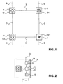
- the FIG. 1 schematically shows a plurality of heaters 1.
- a heating device 1 is understood to mean devices which are typically used in a commercial kitchen. For example, a cooker, oven, fryer, steamer, or microwave oven, etc. In commercial kitchens, such heaters 1 are typically packaged in a set, which may also be referred to as island or island, of a few units (e.g., four to six units). summarized.
- a large kitchen can contain several sets or cooking islands, whereby these cooking islands are independent of each other.
- a single cooking island preferably has between three to twelve individually switchable heaters.
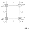
- FIG. 2 shows a heater 1 schematically in detail.
- Each heating device 1 comprises not only the actual heating device 10 (in this case a cooking stove) with which the food is heated, but also an apparatus controller 11.
- the apparatus controller 11 is integrated in the heating device 1.
- the apparatus controller 11 of each heater 1 includes a controller 12, a memory device 13, a communication device 14, and input elements 15.
- the control device 12 essentially serves to control or regulate the heating device 1.
- the control device 12 controls the power supply to the corresponding heating device 1 on the basis of the parameters which are defined or predetermined by the method according to the invention.
- the memory device 13 is used to store data, in particular from a table, which are obtained via the communication device 14.
- the table comprises information or parameters which are directed to the power supply of the individual heating devices 1.
- the controller 12 may retrieve this information from the memory device 13 and thus obtain the parameters for the power supply.
- each heater 1 includes input members 15 such as rotary switches, keyboard blocks, etc., with which the user can operate the heater 1.
- input members 15 such as rotary switches, keyboard blocks, etc.
- the user can specify a desired level of performance, ie a desired cooking level.
- Power levels are understood to mean a certain power consumption of active power from the connection of the power grid.
- each heater 1 has the advantage that no separate, central control unit or control device must be provided, which limits the total power consumption. This can, among other things, reduce costs. Furthermore, this allows flexible assembly of different heaters. In particular, when adding a new heater 1 in an existing cooking island this is advantageous because this eliminates the need to customize a central control unit.
- the heaters 1 are supplied via a connecting line 2 with electrical energy.
- Each heater 1 is connected to its own, separate connection line 2 to the electrical network.
- the connection line 2 can also be a common connecting line, wherein all four heating devices are supplied via the same connecting line.
- the communication devices 14 of the individual Heinz wornen 1 are connected to each other via a bus system 3.
- the communication devices 14 are designed to communicate with the bus system 3 or via the bus system 3 with control devices from the other heaters 1 connected to the bus system 3. That is, the communication device 14 is able to send data to receive and then the controller 12 to provide.
- the bus system may be wired, for example, all communication devices 14 are connected to each other, preferably serially.
- the bus system can also be a wireless network, such as a WLAN network, a Bluetooth network, an IR network, etc.
- new heating devices 1 can be integrated in the network of existing heating devices 1 in a particularly simple manner to get integrated.
- the wireless networks are particularly flexible and easy to implement.
- a wired LAN network can be used.
- the data are directed in particular to the power consumption of the individual heating devices 1 and the total power consumption, as described below with the method according to the invention, as well as to the connected load.
- the apparatus controller 11 thus serves not only the control of the heater 10, but also the control of the maximum total power consumption. It is therefore a decentralized arrangement of a device for controlling the maximum power consumption.
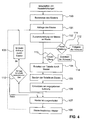
- the flowchart shown shows the inventive method for controlling the consumption of electrical energy for a plurality of electric heaters 1.
- the task of the controller is to limit the total power consumption so that the sum of the power consumption of all individual heaters 1, so the total power consumption, not greater than the predetermined maximum power consumption is or is not greater than the maximum connection value, advantageously limited to a presettable threshold value, for example, as a percentage of the maximum connection value.
- a first step 100 the user switches on one or more heating devices 1.
- the user selects, for example, a temperature or a certain cooking level with which he wants to operate the corresponding heating device 1. From this input the result is the power to be absorbed by each heater 1.
- the total power consumption results from the sum of the power consumption of each individual heating device. The total power consumption should not exceed a given maximum power. With the method according to the invention, the power consumption of the individual heating device with respect to the total power consumption can now be limited such that the maximum power is not exceeded.
- a master M is now determined in step 101.
- each apparatus controller 11 is advantageously equipped so that it can take over the function of the master M.
- individual heaters 1 or stations can only be slaves.
- FIG. 1 the heater 1 is provided with the master state with the reference M. All other heaters 1 have a slave state S1, S2, S3. The heater 1 with the master state can send commands regarding the power consumption to those heaters 1 with the slave state S.
- the bus system 3 is designed such that bus collisions are detected, wherein in the case of a bus collision, the master M is usually redefined.
- the other heating devices 1 queried for their state. If the other heating devices 1 have been switched on later than the switched-on heating device 1, these still do not have a defined state.
- the first switched on heating device 1 will now define as master M. If the other heating devices 1 have been switched on before the switched-on heating device 1, a heating device 1 is already defined as a master M. Then the switched-on heating device will assume the state Slave S. Only one heater can have the state of the master M per cooking island.
- the step follows the query 102 of the slaves S.
- the master M queries all slaves S for the requested performance.
- the performance that the user considers necessary results from the settings of the user, which he inputs or sets via the input elements 15 as already mentioned above.
- step 103 "status message of the slaves S to master M".
- the desired data regarding the power consumption is transmitted to the master M.
- step 104 a table with the desired power consumption of the heaters with the slave state S and those with the master state M.
- the table comprises at least three data areas. In a first data area, data are stored with which the corresponding heating device can be unequivocally identified. In a second data area, the desired, so set by the user, stored power. In a third data area, the assigned power of the individual heating device is stored. The assigned power is calculated by the controller 12 of the master M.
- the master determines the power level for each heater. For example, the master calculates the percentage by which each heating device must lower the desired power, so that the maximum connected load is no longer exceeded. This value is stored in the Assigned Power column in% of the desired power.
- the following table is an example of such a table as created by the Master M becomes.
- the maximum connected load is typically between 8 kW and 45 kW, in the present example 10 kW, with the desired total power consumption being 14 kW. This means that the power has to be reduced by 4 kW or around 31%.
- This value is stored in the "Assigned power in% of desired power" column.
- Desired performance Assigned power in% of desired performance: 1 Master M 3.5 kW 69% 2 Slave S 1 3.5 kW 69% 3 Slave S 2 2.5 kW 69% 4 Slave S 3 5.0 kW 69%
- the power allocated is proportional to all four heaters.
- a certain heating device for example an oven, always receives a higher value.
- heating devices or devices in the warm-up phase generally to receive 100% of the set power, as long as no other connection values are assigned by a heating device defined as master M or else over a defined period of time.
- the heater has a priority state in the warm-up phase. Such priority regimes may be limited in time and / or alternatively alternate with the described proportional regime.
- the control device 12 of the corresponding heating device 1 can now read the data from the memory element 12 and controls its own heating device 1 in accordance with the assigned power. In the flowchart, this is represented by the block 109 Converting the specified power. This means that, for example, the heating device 2, which has been assigned the state of a slave S1, is operated with a power of 69% of the desired power.
- the heaters 1 are now operated for a certain time with the conditions set by the master. Since the user adjusts the power consumption of individual heaters 1 during a cooking process, this requires further queries over the entire on-time of the heaters 1. After a certain dead time For example, after 20 or 30 seconds, in step 106, a renewed query of the slaves S by the master M. The time between the individual polling intervals is understood as a dead time. In this case, in turn, the desired power of each slave S and the master M is queried and stored by the master M in the table. Furthermore, the assigned power is calculated again. In other words, this means that steps 102 to 105 are repeated.
- the dead time may be shorter or longer.
- the dead time is between 1 and 60 seconds, in particular between 10 and 30 seconds.
- FIG. 3 shows the arrangement of the four heaters 1, wherein the slave S2 is turned off in this case.
- Switching off a slave S is noted in the table in that the table has either only three instead of four lines or one empty line.
- the slaves may be assigned a new identification number.
- the bus system 3 is not interrupted. As soon as a switched-off heating device is switched on again, it is in turn queried by the master M.
- slaves S are no longer queried or no longer receive a table.
- decision block 110 it is determined if the query occurs within a predetermined time.
- the query or the receipt of the table within a predetermined time for example, be monitored by each of the slaves S.
- the slaves S determine a new master M with the step 108. Since the table with the performance data has been stored by each slave S in the corresponding memory element, the slaves S are prevented from doing so Lose data regarding the performance restriction.
- the new master M can use the table already created by the previous master.
- Desired performance Assigned power in% of desired performance: 1 Switched off 0 kW 2 Master M (was slave S 1) 3.5 kW 91% 3 Slave S1 (was slave S 2) 2.5 kW 91% 4 Slave S2 (was slave S 3) 5.0kW 91%
- the new master M polls the slaves S periodically after steps 102 to 105.
- the predetermined time is also stored in the memory device 13, taking into account possible bus collisions.
- the master M determines whether a slave, which is still listed in the chronologically preceding table, has not issued a status message. See in FIG. 4 Step 111 No message slave. Subsequently, the address of the slave is released in block 112 enable the address and can be assigned to another slave.
- the master M determines whether a slave has reported, which is not yet listed in the chronologically preceding table. See step 113 new slave. If a new slave is present, it is assigned a new address at step 114.
- the power consumption of the corresponding heater is adjusted.
- the user's desired power is 3.5 kW and the power allocated is 69% of the desired power. If the user now lowers the desired power (e.g., from 3.5 kW to 2.5 kW), the heater will continue to receive 69% of the new desired power (ie, 69% of the 2.5 kW). This does not adversely affect the total power consumption, because the predetermined threshold can not be exceeded.
- the regime is similar. If the user now increases the desired power (eg from 3.5 kW to 4.5 kW), then the heater will continue to receive 69% of the new desired power (ie 69% of the 4.5 kW). As a result, the Bac elaboratesaufiiahme can be greater than the predetermined threshold. This will then be corrected in a new query again. This means that exceeding the threshold value for the time between the individual queries is tolerated.
Landscapes
- Engineering & Computer Science (AREA)
- Power Engineering (AREA)
- Food Science & Technology (AREA)
- Control Of Resistance Heating (AREA)
- Electric Stoves And Ranges (AREA)
- Central Heating Systems (AREA)
- Heat-Pump Type And Storage Water Heaters (AREA)
Claims (9)
- Procédé de commande de la consommation d'énergie électrique pour une pluralité de dispositifs de chauffage (1) électriques d'une cuisine comprenant à chaque fois une commande d'appareil (11), la commande d'appareil (11) incluant un dispositif de commande (12), un dispositif de mémorisation (13), un dispositif de communication (14) et des éléments de saisie (15) pour prédéfinir le niveau de puissance souhaité, les dispositifs de communication (14) des dispositifs de chauffage (1) pouvant communiquer entre eux, l'un des dispositifs de chauffage (1) allumés avec la commande d'appareil (11) correspondante étant défini comme Maître (M), et les autres dispositifs de chauffage (1) allumés avec les commandes d'appareil (11) correspondantes étant définis comme Esclaves (S), le niveau de puissance souhaité ou possible de tous les dispositifs de chauffage (1) connectés étant communiqué au Maître (M) par le biais des dispositifs de communication (14), le Maître (M) déterminant la puissance consommée par tous les dispositifs de chauffage (1) connectés de manière à ce qu'une valeur de seuil prédéfinie ne soit pas dépassée, caractérisé en ce que les Esclaves (S) vérifient à intervalles périodiques s'ils sont interrogés par le Maître (M), une des commandes d'appareil (11) définies jusqu'à présent comme Esclaves devenant le nouveau Maître (M) en l'absence d'interrogation.
- Procédé selon la revendication 1, caractérisé en ce que les dispositifs de communication (14) communiquent par le biais d'un système de bus (3) ou d'un réseau tel qu'un réseau filaire ou un réseau radioélectrique sans fil.
- Procédé selon la revendication 1 ou 2, caractérisé en ce que le Maître (M) crée un tableau, le tableau contenant au moins l'identification de l'Esclave (S) et du Maître (M), la puissance consommée souhaitée par le dispositif de chauffage (1) de l'Esclave (S) correspondant et la puissance consommée déterminée par le Maître (M) pour chaque dispositif de chauffage (1) .
- Procédé selon l'une des revendications précédentes, caractérisé en ce que la puissance maximale disponible est distribuée proportionnellement aux dispositifs de chauffage (1) correspondants en fonction de la puissance consommée souhaitée des dispositifs de chauffage (1) individuels.
- Procédé selon l'une des revendications précédentes, caractérisé en ce que le Maître (M) communique le tableau à tous les Esclaves (S), le tableau étant mémorisé pour chaque dispositif de chauffage (1) par le dispositif de mémorisation (13) correspondant.
- Procédé selon l'une des revendications précédentes, caractérisé en ce que le Maître (M) interroge les Esclaves (S) à intervalles périodiques pour connaître la puissance consommée souhaitée.
- Dispositif de commande de la consommation d'énergie électrique pour une pluralité de dispositifs de chauffage (1) électriques d'une cuisine, chaque dispositif de chauffage (1) comprenant une commande d'appareil (11), la commande d'appareil (11) incluant au moins un dispositif de commande (12), des éléments de saisie (13) pour prédéfinir un niveau de chauffage souhaité, un dispositif de mémorisation (1) pour mémoriser des données et un dispositif de communication (14), chaque commande d'appareil (11) pouvant prendre, au choix, un statut de Maître (M) ou d'Esclave (S), la puissance consommée par tous les dispositifs de chauffage (1) pouvant être déterminée par le Maître (M), caractérisé en ce que les dispositifs ayant le statut d'Esclave (S) vérifient à intervalles périodiques s'ils sont interrogés par le dispositif ayant le statut de Maître (M), le statut de Maître (M) pouvant être attribué à un autre dispositif en l'absence d'interrogation.
- Dispositif selon la revendication 7, caractérisé en ce que les dispositifs de communication (14) de chaque dispositif de chauffage (1) communiquent entre eux par le biais d'un réseau filaire, notamment un système de bus, ou d'un réseau sans fil.
- Dispositif selon la revendication 7 ou 8, caractérisé en ce que les commandes d'appareil (11) ayant le statut d'Esclave (S) peuvent être interrogées à intervalles périodiques par la commande d'appareil ayant le statut de Maître (M) pour connaître la puissance consommée souhaitée.
Applications Claiming Priority (1)
| Application Number | Priority Date | Filing Date | Title |
|---|---|---|---|
| CH17672007 | 2007-11-15 |
Publications (2)
| Publication Number | Publication Date |
|---|---|
| EP2061131A1 EP2061131A1 (fr) | 2009-05-20 |
| EP2061131B1 true EP2061131B1 (fr) | 2010-12-29 |
Family
ID=39682655
Family Applications (1)
| Application Number | Title | Priority Date | Filing Date |
|---|---|---|---|
| EP08168840A Active EP2061131B1 (fr) | 2007-11-15 | 2008-11-11 | Procédé et dispositif destinés à la commande de la distribution d'énergie électrique pour une multitude de dispositifs de chauffage électriques d'une cuisine |
Country Status (3)
| Country | Link |
|---|---|
| EP (1) | EP2061131B1 (fr) |
| AT (1) | ATE493785T1 (fr) |
| DE (1) | DE502008002124D1 (fr) |
Families Citing this family (9)
| Publication number | Priority date | Publication date | Assignee | Title |
|---|---|---|---|---|
| DE102009030725A1 (de) * | 2009-06-26 | 2010-12-30 | Repower Systems Ag | Windpark und Verfahren zum Regeln eines Windparks |
| DE102009036816A1 (de) | 2009-08-10 | 2011-02-17 | Rwe Ag | Steuerung von Ladestationen |
| KR20110099542A (ko) | 2010-03-02 | 2011-09-08 | 삼성전자주식회사 | 수요 반응 시스템 |
| DE102011114344B4 (de) * | 2011-09-21 | 2023-02-09 | Fraunhofer-Gesellschaft zur Förderung der angewandten Forschung e.V. | Leistungssteuereinrichtung und Verfahren zum Lastausgleich eines Netzes |
| JP2014023232A (ja) * | 2012-07-17 | 2014-02-03 | Toshiba Corp | エネルギ管理装置、エネルギ管理方法及びエネルギ管理プログラム |
| JP6237514B2 (ja) * | 2014-07-17 | 2017-11-29 | ソニー株式会社 | 送受電制御装置、送受電制御方法及び送受電制御システム |
| JP6248859B2 (ja) | 2014-08-08 | 2017-12-20 | ソニー株式会社 | 電力供給装置、電力供給方法及び電力供給システム |
| DE102016125572A1 (de) * | 2016-12-23 | 2018-06-28 | Frima International Ag | Verfahren zum Betreiben von mehreren Geräten mit elektrischen Verbrauchern oder Gasverbrauchern und System mit mehreren solchen Geräten |
| CN114094662B (zh) * | 2021-11-18 | 2024-04-23 | 闪极科技(深圳)有限公司 | 多口快速充电器的智能功率分配方法 |
Family Cites Families (6)
| Publication number | Priority date | Publication date | Assignee | Title |
|---|---|---|---|---|
| EP0456872A1 (fr) * | 1990-05-18 | 1991-11-21 | Food Automation-Service Techniques, Inc. | Dispositif de traitement d'aliments |
| IL109402A0 (en) * | 1994-04-22 | 1994-07-31 | Yahav Shimon | Electrical cooking apparatus |
| CH694717A5 (de) | 1999-07-05 | 2005-06-15 | Elro Holding Ag | Steuereinrichtung zur Verteilung elektrischer Energie und Verfahren zum Betrieb der Steuereinrichtung. |
| US6891478B2 (en) * | 2000-06-09 | 2005-05-10 | Jay Warren Gardner | Methods and apparatus for controlling electric appliances during reduced power conditions |
| EP1263108A1 (fr) * | 2001-06-01 | 2002-12-04 | Roke Manor Research Limited | Système de gestion d'énergie pour une communauté |
| US7518894B2 (en) * | 2005-03-31 | 2009-04-14 | Silicon Laboratories Inc. | Distributed power supply system having reassignable master |
-
2008
- 2008-11-11 DE DE502008002124T patent/DE502008002124D1/de active Active
- 2008-11-11 AT AT08168840T patent/ATE493785T1/de active
- 2008-11-11 EP EP08168840A patent/EP2061131B1/fr active Active
Also Published As
| Publication number | Publication date |
|---|---|
| ATE493785T1 (de) | 2011-01-15 |
| DE502008002124D1 (de) | 2011-02-10 |
| EP2061131A1 (fr) | 2009-05-20 |
Similar Documents
| Publication | Publication Date | Title |
|---|---|---|
| EP2061131B1 (fr) | Procédé et dispositif destinés à la commande de la distribution d'énergie électrique pour une multitude de dispositifs de chauffage électriques d'une cuisine | |
| EP1879277B1 (fr) | Ferme à vent tout comme procédé destiné au fonctionnement d'une ferme à vent | |
| EP2267302B1 (fr) | Parc éolien et procédé de gestion d'un parc éolien | |
| EP2192458B1 (fr) | Dispositif de commande et procédé de gestion de l'énergie d'une installation d'automatisation industrielle | |
| EP2868979B1 (fr) | Appareil de cuisson et procédé de commande d'un appareil de cuisson | |
| DE112008000321T5 (de) | Stromversorgungssystem mit mehreren Generatorsätzen | |
| EP2864631B1 (fr) | Parc éolien comprenant plusieurs points d'alimentation du réseau | |
| DE102008001942B3 (de) | Mobiles Heizsystem | |
| EP3639340A1 (fr) | Procédé d'injection de la puissance électrique au moyen d'une unité de production commandée par un convertisseur, en particulier d'une éolienne | |
| DE19502786C2 (de) | Schaltungsanordnung und Verfahren zur gezielten Spannungsversorgung von an einem Versorgungsnetz angeschlossenen elektrischen Geräten | |
| DE102012224128A1 (de) | Verfahren zum Betreiben eines Haushaltsgerätes sowie Haushaltsgerät | |
| AT501422B1 (de) | Wechselrichtersystem zum einspeisen in ein 3-phasennetz sowie wechselrichteranlage für ein 3-phasennetz | |
| DE102010033633B4 (de) | Einschalt-Steuerungsverfahren und Einschalt-Steuerungsvorrichtung | |
| DE19842043A1 (de) | Verfahren und Vorrichtung zur automatischen und verbraucherorientierten Leistungsminimierung elektrischer Verbraucher | |
| EP1949613B1 (fr) | Agencement d'appareils électriques, en particulier pour meuble, avec dispositif de bus et abonnés de bus, et procédé de commande d'un tel agencement d'appareils électriques | |
| EP3369289B1 (fr) | Méthode de contrôle d'un dispositif de cuisson, dispositif de cuisson et élément chauffant | |
| DE102010036157A1 (de) | Verfahren zur Regelung einer Heizeinrichtung für ein Gargerät sowie Heizung für ein Gargerät | |
| EP4217657A1 (fr) | Système de cuisson doté de dispositif de coordination de fin de temps de cuisson cible applicable en commun | |
| EP1067650B1 (fr) | Arrangement de commande de la distribution d'énergie électrique et procédé de fonctionnement | |
| EP3024106B1 (fr) | Dispositif de commutation pour une installation electrique destinee au demarrage temporise apres la reception d'un signal de commande | |
| EP2226500A2 (fr) | Régulateur de parc éolien | |
| DE102006016080A1 (de) | Energieversorgungsvorrichtung für eine Vielzahl von daran anzuschließenden Energieverbrauchern | |
| DE102008043914A1 (de) | System mit zwei Hausgeräten und Verfahren zum Energiemanagement eines derartigen Systems | |
| WO2026017576A1 (fr) | Procédé, système et dispositif de commande pour commander une pluralité de pompes à chaleur actionnées de manière distribuée localement dans un réseau | |
| DE19902997B4 (de) | Verfahren und Vorrichtung zur Beeinflussung der Einwirkung einer Energieoptimierungsanlage zum Begrenzen der elektrischen Leistungsaufnahme mehrerer elektrischer Verbraucher |
Legal Events
| Date | Code | Title | Description |
|---|---|---|---|
| PUAI | Public reference made under article 153(3) epc to a published international application that has entered the european phase |
Free format text: ORIGINAL CODE: 0009012 |
|
| AK | Designated contracting states |
Kind code of ref document: A1 Designated state(s): AT BE BG CH CY CZ DE DK EE ES FI FR GB GR HR HU IE IS IT LI LT LU LV MC MT NL NO PL PT RO SE SI SK TR |
|
| AX | Request for extension of the european patent |
Extension state: AL BA MK RS |
|
| 17P | Request for examination filed |
Effective date: 20091113 |
|
| AKX | Designation fees paid |
Designated state(s): AT CH DE FR IT LI |
|
| GRAP | Despatch of communication of intention to grant a patent |
Free format text: ORIGINAL CODE: EPIDOSNIGR1 |
|
| GRAS | Grant fee paid |
Free format text: ORIGINAL CODE: EPIDOSNIGR3 |
|
| GRAA | (expected) grant |
Free format text: ORIGINAL CODE: 0009210 |
|
| AK | Designated contracting states |
Kind code of ref document: B1 Designated state(s): AT CH DE FR IT LI |
|
| REG | Reference to a national code |
Ref country code: CH Ref legal event code: EP |
|
| REF | Corresponds to: |
Ref document number: 502008002124 Country of ref document: DE Date of ref document: 20110210 Kind code of ref document: P |
|
| REG | Reference to a national code |
Ref country code: DE Ref legal event code: R096 Ref document number: 502008002124 Country of ref document: DE Effective date: 20110210 |
|
| PLBE | No opposition filed within time limit |
Free format text: ORIGINAL CODE: 0009261 |
|
| STAA | Information on the status of an ep patent application or granted ep patent |
Free format text: STATUS: NO OPPOSITION FILED WITHIN TIME LIMIT |
|
| 26N | No opposition filed |
Effective date: 20110930 |
|
| REG | Reference to a national code |
Ref country code: DE Ref legal event code: R097 Ref document number: 502008002124 Country of ref document: DE Effective date: 20110930 |
|
| REG | Reference to a national code |
Ref country code: AT Ref legal event code: MM01 Ref document number: 493785 Country of ref document: AT Kind code of ref document: T Effective date: 20131111 |
|
| PG25 | Lapsed in a contracting state [announced via postgrant information from national office to epo] |
Ref country code: AT Free format text: LAPSE BECAUSE OF NON-PAYMENT OF DUE FEES Effective date: 20131111 |
|
| REG | Reference to a national code |
Ref country code: FR Ref legal event code: PLFP Year of fee payment: 8 |
|
| REG | Reference to a national code |
Ref country code: FR Ref legal event code: PLFP Year of fee payment: 9 |
|
| REG | Reference to a national code |
Ref country code: FR Ref legal event code: PLFP Year of fee payment: 10 |
|
| REG | Reference to a national code |
Ref country code: DE Ref legal event code: R081 Ref document number: 502008002124 Country of ref document: DE Owner name: ILLINOIS TOOL WORKS INC., GLENVIEW, US Free format text: FORMER OWNER: ELRO (HOLDING) AG, BREMGARTEN, CH |
|
| REG | Reference to a national code |
Ref country code: CH Ref legal event code: NV Representative=s name: BOVARD SA NEUCHATEL CONSEILS EN PROPRIETE INTE, CH |
|
| P01 | Opt-out of the competence of the unified patent court (upc) registered |
Effective date: 20231101 |
|
| REG | Reference to a national code |
Ref country code: CH Ref legal event code: U11 Free format text: ST27 STATUS EVENT CODE: U-0-0-U10-U11 (AS PROVIDED BY THE NATIONAL OFFICE) Effective date: 20251201 |
|
| PGFP | Annual fee paid to national office [announced via postgrant information from national office to epo] |
Ref country code: DE Payment date: 20251128 Year of fee payment: 18 |
|
| PGFP | Annual fee paid to national office [announced via postgrant information from national office to epo] |
Ref country code: IT Payment date: 20251119 Year of fee payment: 18 |
|
| PGFP | Annual fee paid to national office [announced via postgrant information from national office to epo] |
Ref country code: FR Payment date: 20251125 Year of fee payment: 18 |
|
| PGFP | Annual fee paid to national office [announced via postgrant information from national office to epo] |
Ref country code: CH Payment date: 20251201 Year of fee payment: 18 |
|
| REG | Reference to a national code |
Ref country code: CH Ref legal event code: R18 Free format text: ST27 STATUS EVENT CODE: U-0-0-R10-R18 (AS PROVIDED BY THE NATIONAL OFFICE) Effective date: 20260209 |
|
| REG | Reference to a national code |
Ref country code: CH Ref legal event code: R18 Free format text: ST27 STATUS EVENT CODE: U-0-0-R10-R18 (AS PROVIDED BY THE NATIONAL OFFICE) Effective date: 20260320 |