EP2061300B1 - An agricultural machine - Google Patents
An agricultural machine Download PDFInfo
- Publication number
- EP2061300B1 EP2061300B1 EP07808885A EP07808885A EP2061300B1 EP 2061300 B1 EP2061300 B1 EP 2061300B1 EP 07808885 A EP07808885 A EP 07808885A EP 07808885 A EP07808885 A EP 07808885A EP 2061300 B1 EP2061300 B1 EP 2061300B1
- Authority
- EP
- European Patent Office
- Prior art keywords
- fore
- disc
- discs
- angle
- structure element
- Prior art date
- Legal status (The legal status is an assumption and is not a legal conclusion. Google has not performed a legal analysis and makes no representation as to the accuracy of the status listed.)
- Not-in-force
Links
- 239000002689 soil Substances 0.000 claims abstract description 40
- 238000004519 manufacturing process Methods 0.000 description 8
- 230000015572 biosynthetic process Effects 0.000 description 5
- 230000003247 decreasing effect Effects 0.000 description 3
- 230000009471 action Effects 0.000 description 2
- 230000008901 benefit Effects 0.000 description 2
- 230000009467 reduction Effects 0.000 description 2
- 229910000831 Steel Inorganic materials 0.000 description 1
- 230000000295 complement effect Effects 0.000 description 1
- 239000000470 constituent Substances 0.000 description 1
- 238000010276 construction Methods 0.000 description 1
- 238000005520 cutting process Methods 0.000 description 1
- 238000010586 diagram Methods 0.000 description 1
- 238000006073 displacement reaction Methods 0.000 description 1
- 238000009826 distribution Methods 0.000 description 1
- 230000000694 effects Effects 0.000 description 1
- 230000001747 exhibiting effect Effects 0.000 description 1
- 230000003116 impacting effect Effects 0.000 description 1
- 238000000034 method Methods 0.000 description 1
- 210000000056 organ Anatomy 0.000 description 1
- 230000004043 responsiveness Effects 0.000 description 1
- 238000003892 spreading Methods 0.000 description 1
- 230000007480 spreading Effects 0.000 description 1
- 239000010959 steel Substances 0.000 description 1
- 239000004575 stone Substances 0.000 description 1
- 238000003971 tillage Methods 0.000 description 1
- 230000007704 transition Effects 0.000 description 1
Images

Classifications
-
- A—HUMAN NECESSITIES
- A01—AGRICULTURE; FORESTRY; ANIMAL HUSBANDRY; HUNTING; TRAPPING; FISHING
- A01B—SOIL WORKING IN AGRICULTURE OR FORESTRY; PARTS, DETAILS, OR ACCESSORIES OF AGRICULTURAL MACHINES OR IMPLEMENTS, IN GENERAL
- A01B21/00—Harrows with rotary non-driven tools
- A01B21/08—Harrows with rotary non-driven tools with disc-like tools
- A01B21/086—Harrows with rotary non-driven tools with disc-like tools of the type in which the disc-like tools are individually mounted
Definitions
- the invention relates to an agricultural machine comprising a plurality of discs for soil cultivation, whereof at least one fore disc is mounted on a fore structure element and at least one rear disc is mounted on a rear structure element via a respective connecting member.
- the fore and the rear disc have rotation axes that, projected in a horizontal plane, form angles to a conceptual horizontal cross-axis that is perpendicular to the intended driving direction of the agricultural machine. More precisely a first angle between the rotation axis of the fore disc and the cross-axis is greater than a second angle between the rotation axis of the rear disc and the cross-axis.
- a long-known type of so-called disc cultivator displays disc axles that form the shape of an X, wherein a plurality of rotatable discs are positioned at distance from each other along each disc axle and ⁇ threaded' thereon so that their rotation axes are in common with the respective disc axle.
- Such 'X-cultivators' are associated with a range of known disadvantages, such as large space requirement parallel to the driving direction of the cultivator, difficulties in replacing discs, and in many cases inadequate results in soil cultivation.
- discs to the right are angled in the opposite direction in relation to discs on the left in the same row, wherein discs in the rear row are angled in the opposite direction in relation to discs in front. Furthermore the discs are normally angled so that the fore row's discs effect a certain lateral outward displacement of soil, while the rear row's discs to a certain extent displace soil inwards.
- a problem with formation of a soil wall in the centre of the area over which the machine passes has been countered by rotation axes for discs in the fore row exhibiting greater angles to the cross-direction of the machine than rotation axes for discs in the rear row.
- the smaller angle for the discs in the rear row compensates for the greater amount of soil that would otherwise have been displaced by the rear discs since they, in addition to soil displaced by the fore discs, also displace further soil that had not been torn up by the fore discs.
- the smaller cutting angle for the rear discs means that soil walling in the area over which the machine passes is decreased.
- An agricultural machine in accordance with the preamble of claim 1 is known from WO-A-2004/004437 .
- An aim of the invention is to simplify manufacturing of an agricultural machine of the initially described type.
- a further aim of the invention is to make manufacturing of an agricultural machine of the initially described type cheaper and more cost-effective.
- Yet another aim of the invention is to make an agricultural machine of the initially described type more maintenance-friendly.
- Another aim of the invention is to provide an agricultural machine of the initially described type that is arranged in such a way that the specified disadvantages with the known solutions are reduced to the greatest possible extent.
- That the fore and the rear structure element are orientated at an angle relative to each other means that they are not parallel. It is thereby possible in an easy way to achieve the advantageous angle difference between the fore and rear discs through suitable choice of the angle between the respective structure element on which the discs are mounted.
- An angle between the rotation axis of the fore disc and the fore structure element is preferably essentially of the same magnitude as an angle between the rotation axis of the rear disc and the rear structure element.
- the angle between the structure elements is thereby essentially of the same magnitude as the difference between the first and the second angle.
- the difference between the first and the second angle is preferably 2-6 degrees. It has been shown that this choice of angle difference between the fore and rear discs gives very good results in attempts to eliminate wall formation after the machine. The best results have emerged when the difference between the first and the second angle is approximately 3 degrees.
- the relative positioning of the discs can be arranged in any suitable way at all. e.g. in rows that have their main extension perpendicular to the intended driving direction of the agricultural machine.
- at least two fore discs and at least two rear discs are distributed on each side of a conceptual, longitudinal axis, which is parallel with the driving direction, and wherein the left fore disc and the left rear disc are angled in the opposite direction in relation to the right fore disc and the right rear disc, respectively.
- the fore and the rear discs are preferably angled so that during soil cultivation they displace soil outwards and inwards respectively. i.e. away from or towards the longitudinal axis.
- the left fore disc is mounted on a fore structure element and the right rear disc is mounted on a right rear structure element via a respective connecting member, and wherein the fore structure element and the right rear structure element are orientated at an angle relative to each other.
- an angle between the rotation axis of the left fore disc and the fore structure element is preferably essentially of the same magnitude as an angle between the rotation axis of the right rear disc and the right rear structure element.
- the angle between the fore structure element and the right rear structure element is thereby of the same magnitude as the difference between the angle between the rotation axis of the left fore disc and the cross-axis, and the angle between the rotation axis of the right rear disc and the cross-axis.
- the right fore disc is mounted on a fore structure element and the left rear disc is mounted on a left rear structure element via a respective connecting member, and wherein the fore structure element and the left rear structure element are orientated at an angle relative to each other.
- an angle between the rotation axis of the right fore disc and the fore structure element is preferably essentially of the same magnitude as an angle between the rotation axis of the left rear disc and the left rear structure element.
- the angle between the fore structure element and the left rear structure element is thereby of the same magnitude as the difference between the angle between the rotation axis of the right fore disc and the cross-axis, and the angle between the rotation axis of the left rear disc and the cross-axis.
- the relative distance between the inner fore disc and the inner rear disc is greater than the relative distance between the outer fore disc and the outer rear disc.
- a distance between those of the rear discs that are located nearest the longitudinal axis is preferably greater than a distance between those of the fore discs that are located nearest the longitudinal axis. This achieves a further reduction of tendencies for wall formation in the middle of the area over which the machine passes during soil cultivation.
- the at least one left fore disc and the at least one right rear disc are mounted on a respective structure element via a respective connecting member, wherein an angle between the structure elements is essentially of the same magnitude as the difference between the first and the second angle.
- the angles between the discs and the respective structure element can be essentially similar, and that the connecting member for left fore disc and the rear right discs can be similar.
- the at least one right fore disc and the at least one left rear disc can be mounted on a respective structure element via a respective connecting member, wherein the angle between the structure elements is essentially of the same magnitude as the difference between the first and the second angle.
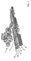
- Fig. 1 shows a tractor 1 with a rear linked agricultural machine 2, in the form of a disc cultivator, which displays a plurality of discs 3 for soil cultivation.
- Each disc 3 is via a connecting member 6 mounted on a structure element 5c, 5d, as is described more closely in the following.
- the structure elements 5c, 5d are in turn mounted on a frame 4 at the agricultural machine 2.
- the agricultural machine 2 also comprises five ring roller sections 9 which, in the intended driving direction of the agricultural machine, are arranged behind the discs 3.
- the machine 2 can be provided with some other type of similar organ, e.g. one or more packer wheels or similar.
- Fig. 2 shows a top view of a portion of the agricultural machine 2, the intended driving direction of which is indicated with an arrow F.
- the structure elements 5a1-5f are elongated and provided in the form of beams, in this example steel pipe with quadratic cross-section.
- the structure elements 5a1-5f are distributed as inner structure elements 5a1, 5a2, 5b1, 5b2 and outer structure elements 5c, 5d, 5e, 5f.
- the dividing areas for the inner and outer structure elements are indicated in Fig. 2 with dashed lines U.
- the agricultural machine 2 is in a known way adapted so that the outer structure elements 5c, 5d, 5e, 5f are jointed at outer ends of the inner structure elements 5a1, 5a2, 5b1, 5b2, so that the responsiveness of the machine on soil irregularities is improved, and the outer structure elements 5c, 5d, 5e, 5f can be swung aside for decreasing the width of the machine 2 and facilitating road transport.
- the agricultural machine 2 can according to the invention be provided without such jointed outer structure elements. Instead it can display only rigidly co-bound structure elements, e.g. corresponding to the inner structure elements shown in Fig. 3 .
- the inner structure elements are distributed as a left positioned and a right positioned fore structure element 5a1, 5a2, and a left positioned and a right positioned rear structure element 5b1, 5b2. It should be noted that the fore inner structure element can naturally be replaced with a single structure element, or with more than two structure elements.
- a plurality of connecting members 6 each singly connect a disc 3 with the respective structure element 5a1-5b2, e.g. in a way described in the application associated with Swedish patent SE523890 and incorporated here by means ofcitation.
- Each connecting member 6 comprises an arm 7 and a fastening device 8, in the form of a clamp connection 8. for fastening of the connecting member 6 according to known technique to the respective structure element 5a1-5b2.
- Each disc 3 is rotatably mounted on a respective arm 7 via a hub, so that the disc 3 can rotate around a respective rotation axis through its centre 3.
- a rubber element (not shown) positioned between the clamp connection 8 and the respective structure element 5a1-5b2 allows a springing turning action of the clamp connection 8 around the structure element, so that the disc 3 can execute a springing action in a vertical plane, e.g. in the event of the movement of the machine 2 impacting against a hard object such as a stone.
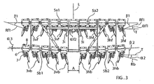
- Fig. 3 shows a detail of Fig. 2 , more precisely the inner structure elements 5a1-5b2, which bear a respective plurality fore and a plurality rear of the discs 3vf, 3hf, 3vb, 3hb, which are rotatable and angled.
- the rotation axes of the discs are angled partly in a horizontal plane (plane of the diagram) and also in a vertical plane.
- the rear discs 3vb, 3hb are in the horizontal plane angled in the opposite direction in relation to the fore discs 3vf, 3hf.
- the discs are furthermore arranged symmetrically in a plurality on each side of a a conceptual, horizontal longitudinal axis L. which is parallel to the intended driving direction of the agricultural machine 2.
- the left fore and rear discs 3vf, 3vb are in the horizontal plane angled in the opposite direction in relation to the right fore and rear discs 3vf, 3hf respectively.
- the discs are arranged so that each one of the fore discs 3vf, 3hf, at movement of the agricultural machine in the driving direction, laterally displaces soil, and each one of the rear discs 3vb, 3hb in the opposite direction liberally displaces at least a part of the soil displaced by a fore disc 3vf, 3hf.
- the first angle ⁇ f1 is greater than the second angle ⁇ 2, and the difference between the angles is approximately 3 degrees.
- the difference in angle is achieved through that the rear inner structure elements 5b1, 5b2 are angled in relation to the fore inner structure elements 5a1, 5a2. More precisely, the fore structure elements are parallel to the cross-axis T, while the rear structure elements 5b1, 5b2 are angled to the cross-axis T by an amount ⁇ 3 that corresponds to the difference between the first and the second angle ⁇ f1, ⁇ 2. This means that the angles between the discs and the respective structure element can be essentially similar. As can be seen in Fig.
- an angle ⁇ 1 between the rotation axes Rf1 of the left fore discs 3vf and the left fore structure element 5a1 is essentially of the same magnitude as an angle ⁇ 2 between the rotation axes Rb of the right rear discs 3hb and the right rear structure element 5b2, and in addition an angle ⁇ 1 between the rotation axes Rf1 of the right fore discs 3hf and the right fore structure element 5a2 is essentially of the same magnitude as an angle ⁇ 2 between the rotation axes Rb of the left rear discs 3vb and the left rear structure element 5b1.
- the connecting members 6 for the left fore discs 3vf and the right rear discs 3hb can thereby be similar and the connecting members 6 for the right fore discs 3hf and the left rear discs 3vb can be similar.
- the arrangement with the angled structure elements 5b1, 5b2 means that the relative distance X ( Fig. 3 ) between an inner fore and an inner rear disc is greater than the relative distance Y between an outer fore and an outer rear disc.
- X Fig. 3
- Y the relative distance between an outer fore and an outer rear disc.
- the risk is decreased of wall forming of soil in the middle of the area over which the machine passes.
- At least one ring roller section 9 is provided at the central portion of the machine, behind the rear discs.
- the distance of that ring roller section to the rear discs in the central portion of the machine is less than the distance between the rear and fore discs in the mentioned central portion. This means that soil set in inward movement by the rear discs, due to contact with the behind-lying ring roller section is transported a shorter distance in the cross direction than soil set in outward movement by the fore discs. This contributes in its turn to further increase the net transport of soil outwards.
- a distance A between the rear discs 3vb, 3hb, which are located nearest the longitudinal axis L is greater than a distance between the fore discs 3i that are located nearest the longitudinal axis (L). This achieves a further reduction of tendencies for wall formation in the middle of the area over which the machine 2 passes during cultivation.
- the agricultural machine 2 in the embodiment described above is with the jointed outer structure elements 5c, 5d, 5e, 5f designed with angled inner rear structure elements 5b1. 5b2 and in a cross-direction orientated outer rear structure elements 5d, 5f.
- the agricultural machine 2 can be designed with all rear structure elements arranged at an angle ⁇ 3 to the cross-axis T.
- the disc-bearing structure elements 5a1, 5a2. 5b1, 5b2 that are shown in Fig. 3 can comprise all disc-bearing structure elements on the agricultural machine 2.
- An embodiment with all rear structure elements arranged at an angle ⁇ 3 to the cross-axis can further improve the soil tillage result.
- the left fore and rear discs can be displaced along the longitudinal axis L in relation to the right fore and rear discs.
- the rear structure elements 5b1, 5b2 can be parallel to the cross-axis T. and the fore structure elements 5a1, 5a2 can be angled so that their outer ends are positioned further forward in the driving direction F, whereby the above described angle difference is achieved.
Landscapes
- Life Sciences & Earth Sciences (AREA)
- Engineering & Computer Science (AREA)
- Mechanical Engineering (AREA)
- Soil Sciences (AREA)
- Environmental Sciences (AREA)
- Soil Working Implements (AREA)
Abstract
Description
- The invention relates to an agricultural machine comprising a plurality of discs for soil cultivation, whereof at least one fore disc is mounted on a fore structure element and at least one rear disc is mounted on a rear structure element via a respective connecting member. The fore and the rear disc have rotation axes that, projected in a horizontal plane, form angles to a conceptual horizontal cross-axis that is perpendicular to the intended driving direction of the agricultural machine. More precisely a first angle between the rotation axis of the fore disc and the cross-axis is greater than a second angle between the rotation axis of the rear disc and the cross-axis.
- A long-known type of so-called disc cultivator displays disc axles that form the shape of an X, wherein a plurality of rotatable discs are positioned at distance from each other along each disc axle and `threaded' thereon so that their rotation axes are in common with the respective disc axle. Such 'X-cultivators' are associated with a range of known disadvantages, such as large space requirement parallel to the driving direction of the cultivator, difficulties in replacing discs, and in many cases inadequate results in soil cultivation.
- Several of these disadvantages are absent at another known type of agricultural machine that comprises a fore and a rear row of angled discs, which rows are orientated in the cross-direction of the machine, and where the discs are mounted on structure elements in the form of beams via respective connecting members. The discs on the fore row are directed in a common direction and the discs on the rear row are directed in the opposite direction. However this solution is associated with the disadvantage that the machine is unstable in the lateral direction.
- To rectify the mentioned lateral instability, another arrangement presents a solution where discs to the right are angled in the opposite direction in relation to discs on the left in the same row, wherein discs in the rear row are angled in the opposite direction in relation to discs in front. Furthermore the discs are normally angled so that the fore row's discs effect a certain lateral outward displacement of soil, while the rear row's discs to a certain extent displace soil inwards.
- A problem with formation of a soil wall in the centre of the area over which the machine passes has been countered by rotation axes for discs in the fore row exhibiting greater angles to the cross-direction of the machine than rotation axes for discs in the rear row. The smaller angle for the discs in the rear row compensates for the greater amount of soil that would otherwise have been displaced by the rear discs since they, in addition to soil displaced by the fore discs, also displace further soil that had not been torn up by the fore discs. Thus at machines where the fore discs are adapted to displace soil laterally during movement of the agricultural machine in the driving direction and the rear discs are adapted to laterally displace in the opposite direction the soil displaced by the fore discs, the smaller cutting angle for the rear discs means that soil walling in the area over which the machine passes is decreased.
- A disadvantage with known types of disc cultivators that comprise such fore and rear rows of discs, where rotation axes for discs in the fore row exhibit greater angles to the cross-direction of the machine than rotation axes for discs in the rear row, is that the respecting connecting members that connect the discs with the beams must be provided in several embodiments, depending on whether the discs are to sit in fore or rear. This means that the number of types of parts that are included in the machine becomes relatively high, which renders production relatively complicated and expensive.
- An agricultural machine in accordance with the preamble of claim 1 is known from
WO-A-2004/004437 . - An aim of the invention is to simplify manufacturing of an agricultural machine of the initially described type.
- A further aim of the invention is to make manufacturing of an agricultural machine of the initially described type cheaper and more cost-effective.
- Yet another aim of the invention is to make an agricultural machine of the initially described type more maintenance-friendly.
- Another aim of the invention is to provide an agricultural machine of the initially described type that is arranged in such a way that the specified disadvantages with the known solutions are reduced to the greatest possible extent.
- This aim is achieved with an agricultural machine of the initially described type, wherein the fore and the rear structure element are orientated at an angle relative to each other.
- That the fore and the rear structure element are orientated at an angle relative to each other means that they are not parallel. It is thereby possible in an easy way to achieve the advantageous angle difference between the fore and rear discs through suitable choice of the angle between the respective structure element on which the discs are mounted. An angle between the rotation axis of the fore disc and the fore structure element is preferably essentially of the same magnitude as an angle between the rotation axis of the rear disc and the rear structure element. The angle between the structure elements is thereby essentially of the same magnitude as the difference between the first and the second angle. This in its turn makes it possible to use identical connecting members for the discs, which simplifies manufacturing of the agricultural machine. This in its turn makes manufacturing of the agricultural machine cheaper and more cost-effective. In addition it becomes possible to decrease the number of constituent spare parts constructions, which makes the agricultural machine more maintenance-friendly.
- The difference between the first and the second angle is preferably 2-6 degrees. It has been shown that this choice of angle difference between the fore and rear discs gives very good results in attempts to eliminate wall formation after the machine. The best results have emerged when the difference between the first and the second angle is approximately 3 degrees.
- It should be noted that the relative positioning of the discs can be arranged in any suitable way at all. e.g. in rows that have their main extension perpendicular to the intended driving direction of the agricultural machine. Generally at least two fore discs and at least two rear discs are distributed on each side of a conceptual, longitudinal axis, which is parallel with the driving direction, and wherein the left fore disc and the left rear disc are angled in the opposite direction in relation to the right fore disc and the right rear disc, respectively. Therein the fore and the rear discs are preferably angled so that during soil cultivation they displace soil outwards and inwards respectively. i.e. away from or towards the longitudinal axis.
- Preferably, the left fore disc is mounted on a fore structure element and the right rear disc is mounted on a right rear structure element via a respective connecting member, and wherein the fore structure element and the right rear structure element are orientated at an angle relative to each other. Thereby an angle between the rotation axis of the left fore disc and the fore structure element is preferably essentially of the same magnitude as an angle between the rotation axis of the right rear disc and the right rear structure element. The angle between the fore structure element and the right rear structure element is thereby of the same magnitude as the difference between the angle between the rotation axis of the left fore disc and the cross-axis, and the angle between the rotation axis of the right rear disc and the cross-axis. This in its turn makes it possible to use identical connecting members for the left fore disc and the right rear disc, which simplifies manufacturing of the agricultural machine.
- In a corresponding way, preferably, the right fore disc is mounted on a fore structure element and the left rear disc is mounted on a left rear structure element via a respective connecting member, and wherein the fore structure element and the left rear structure element are orientated at an angle relative to each other. Therein an angle between the rotation axis of the right fore disc and the fore structure element is preferably essentially of the same magnitude as an angle between the rotation axis of the left rear disc and the left rear structure element. The angle between the fore structure element and the left rear structure element is thereby of the same magnitude as the difference between the angle between the rotation axis of the right fore disc and the cross-axis, and the angle between the rotation axis of the left rear disc and the cross-axis. This in its turn makes it possible to use identical connecting members for the right fore disc and the left rear disc, which simplifies manufacturing of the agricultural machine.
- Preferably, where at least two fore discs and at least two rear discs are located on each side of the longitudinal axis, whereof an inner fore disc and an inner rear disc are located nearer the longitudinal axis than an outer fore disc and an outer rear disc, respectively, the relative distance between the inner fore disc and the inner rear disc is greater than the relative distance between the outer fore disc and the outer rear disc. This achieves a distribution of the discs in the longitudinal direction of the machine, which comes to counteract the tendency of the agricultural machine, on the basis of its self-frequency, at an unfavourable combination of soil consistency and driving speed, to execute a repeated hopping movement. More precisely, a spreading of soil cultivating discs in the intended driving direction of the machine is achieved, which comes to counteract the self-oscillating tendencies that, at an unfavourable combination of soil consistency and driving speed, arise with a concentration of discs to a few points along the driving direction.
- A distance between those of the rear discs that are located nearest the longitudinal axis is preferably greater than a distance between those of the fore discs that are located nearest the longitudinal axis. This achieves a further reduction of tendencies for wall formation in the middle of the area over which the machine passes during soil cultivation.
- Preferably, the at least one left fore disc and the at least one right rear disc are mounted on a respective structure element via a respective connecting member, wherein an angle between the structure elements is essentially of the same magnitude as the difference between the first and the second angle. This means that the angles between the discs and the respective structure element can be essentially similar, and that the connecting member for left fore disc and the rear right discs can be similar. This simplifies production of the agricultural machine since a number of component parts can be manufactured with identical design. Naturally, with achievement of the corresponding advantage, the at least one right fore disc and the at least one left rear disc can be mounted on a respective structure element via a respective connecting member, wherein the angle between the structure elements is essentially of the same magnitude as the difference between the first and the second angle.
- Embodiments of the invention will be described in more detail below with reference to the drawings in which
-
Fig. 1 is a perspective view obliquely from behind of a tractor with a rear linked agricultural machine according to a preferred embodiment of the invention, -
Fig. 2 shows a top view of a portion of the agricultural machine inFig. 1 , and -
Fig. 3 shows a detail of the portion inFig. 2 . -
Fig. 1 shows a tractor 1 with a rear linked agricultural machine 2, in the form of a disc cultivator, which displays a plurality ofdiscs 3 for soil cultivation. Eachdisc 3 is via a connectingmember 6 mounted on astructure element structure elements discs 3. As an alternative or complement to such ring roller sections 9 the machine 2 can be provided with some other type of similar organ, e.g. one or more packer wheels or similar. -
Fig. 2 shows a top view of a portion of the agricultural machine 2, the intended driving direction of which is indicated with an arrow F. The structure elements 5a1-5f are elongated and provided in the form of beams, in this example steel pipe with quadratic cross-section. The structure elements 5a1-5f are distributed as inner structure elements 5a1, 5a2, 5b1, 5b2 andouter structure elements Fig. 2 with dashed lines U. The agricultural machine 2 is in a known way adapted so that theouter structure elements outer structure elements Fig. 3 . - The inner structure elements are distributed as a left positioned and a right positioned fore structure element 5a1, 5a2, and a left positioned and a right positioned rear structure element 5b1, 5b2. It should be noted that the fore inner structure element can naturally be replaced with a single structure element, or with more than two structure elements. A plurality of connecting
members 6 each singly connect adisc 3 with the respective structure element 5a1-5b2, e.g. in a way described in the application associated with Swedish patentSE523890 member 6 comprises an arm 7 and afastening device 8, in the form of aclamp connection 8. for fastening of the connectingmember 6 according to known technique to the respective structure element 5a1-5b2. Eachdisc 3 is rotatably mounted on a respective arm 7 via a hub, so that thedisc 3 can rotate around a respective rotation axis through itscentre 3. A rubber element (not shown) positioned between theclamp connection 8 and the respective structure element 5a1-5b2 allows a springing turning action of theclamp connection 8 around the structure element, so that thedisc 3 can execute a springing action in a vertical plane, e.g. in the event of the movement of the machine 2 impacting against a hard object such as a stone. - Through the described connection with structure elements 5a1-5b2 mainly orientated in the across direction the
discs 3 arc arranged in two rows that have their main extension perpendicular to the intended driving direction of the agricultural machine. -
Fig. 3 shows a detail ofFig. 2 , more precisely the inner structure elements 5a1-5b2, which bear a respective plurality fore and a plurality rear of the discs 3vf, 3hf, 3vb, 3hb, which are rotatable and angled. The rotation axes of the discs are angled partly in a horizontal plane (plane of the diagram) and also in a vertical plane. The rear discs 3vb, 3hb are in the horizontal plane angled in the opposite direction in relation to the fore discs 3vf, 3hf. The discs are furthermore arranged symmetrically in a plurality on each side of a a conceptual, horizontal longitudinal axis L. which is parallel to the intended driving direction of the agricultural machine 2. The left fore and rear discs 3vf, 3vb are in the horizontal plane angled in the opposite direction in relation to the right fore and rear discs 3vf, 3hf respectively. - The discs are arranged so that each one of the fore discs 3vf, 3hf, at movement of the agricultural machine in the driving direction, laterally displaces soil, and each one of the rear discs 3vb, 3hb in the opposite direction liberally displaces at least a part of the soil displaced by a fore disc 3vf, 3hf.
- As can be seen in
Fig. 3 , the rotation axes Rf1 for all fore discs 3vf, 3hf on the fore structure elements 5a1, 5a2, apart from the two sitting nearest the longitudinal axis L, each one, projected in the horizontal plane, form a first angle αf1 to a conceptual horizontal cross-axis T that is perpendicular to the intended driving direction F of the agricultural machine 2. The rotation axes Rb for all rear discs 3vb, 3hb on the rear structure element 5b, each one, projected in the horizontal plane, form a second angle α2 to the cross-axis T. The first angle αf1 is greater than the second angle α2, and the difference between the angles is approximately 3 degrees. - The difference in angle is achieved through that the rear inner structure elements 5b1, 5b2 are angled in relation to the fore inner structure elements 5a1, 5a2. More precisely, the fore structure elements are parallel to the cross-axis T, while the rear structure elements 5b1, 5b2 are angled to the cross-axis T by an amount α3 that corresponds to the difference between the first and the second angle αf1, α2. This means that the angles between the discs and the respective structure element can be essentially similar. As can be seen in
Fig. 3 an angle β1 between the rotation axes Rf1 of the left fore discs 3vf and the left fore structure element 5a1 is essentially of the same magnitude as an angle β2 between the rotation axes Rb of the right rear discs 3hb and the right rear structure element 5b2, and in addition an angle β1 between the rotation axes Rf1 of the right fore discs 3hf and the right fore structure element 5a2 is essentially of the same magnitude as an angle β2 between the rotation axes Rb of the left rear discs 3vb and the left rear structure element 5b1. The connectingmembers 6 for the left fore discs 3vf and the right rear discs 3hb can thereby be similar and the connectingmembers 6 for the right fore discs 3hf and the left rear discs 3vb can be similar. - As can be seen in
Fig. 2 and3 the arrangement with the angled structure elements 5b1, 5b2 means that the relative distance X (Fig. 3 ) between an inner fore and an inner rear disc is greater than the relative distance Y between an outer fore and an outer rear disc. In particular there is achieved a varying distance relationship between the fore row of discs 3vf, 3hf and the rear row of discs 3vb, 3hb. This comes to counteract the tendency of the agricultural machine 2, on the basis of its self-frequency, at an unfavourable combination of soil consistency and driving speed, to execute a repeated hopping movement. In addition the risk is decreased of wall forming of soil in the middle of the area over which the machine passes. The reason is that soil that during conveyance of the machine is set in a lateral movement by the fore discs comes to be displaced further to the side in the central portion of the machine than at its outer parts. The reason for this is in its turn that at the central portion of the machine, the soil set in an outward movement can travel a greater distance before it comes into contact with the rear discs. This transport of soil outwards comes to compensate for the described above inward transport of soil, which is caused by the rear discs displacing inwards both soil that has been torn up by the fore discs and also soil that is torn up by the rear discs. - Preferably at least one ring roller section 9 is provided at the central portion of the machine, behind the rear discs. Preferably the distance of that ring roller section to the rear discs in the central portion of the machine is less than the distance between the rear and fore discs in the mentioned central portion. This means that soil set in inward movement by the rear discs, due to contact with the behind-lying ring roller section is transported a shorter distance in the cross direction than soil set in outward movement by the fore discs. This contributes in its turn to further increase the net transport of soil outwards.
- As can be seen in
Fig. 3 . the rotation axes for the twofore discs 3i that are located nearest the longitudinal axis L. each one, projected in the horizontal plane, forms a third angle αf2 to the conceptual horizontal cross-axis T, which is greater than the first angle αf1. - As can also be seen in
Fig. 3 . a distance A between the rear discs 3vb, 3hb, which are located nearest the longitudinal axis L is greater than a distance between thefore discs 3i that are located nearest the longitudinal axis (L). This achieves a further reduction of tendencies for wall formation in the middle of the area over which the machine 2 passes during cultivation. - The agricultural machine 2 in the embodiment described above is with the jointed
outer structure elements rear structure elements Fig. 3 can comprise all disc-bearing structure elements on the agricultural machine 2. An embodiment with all rear structure elements arranged at an angle α3 to the cross-axis can further improve the soil tillage result. This is due to that the angles on the rear disc row at the transitions between outer 5d, 5f and inner 5b1, 5b2 rear structure elements are lacking at which angles some wall formation of soil can otherwise occur. However an advantage with the embodiment described above, with outerrear structure elements - A large number of alternatives to the embodiments described above are contained within the scope of the patent claims. For example the left fore and rear discs can be displaced along the longitudinal axis L in relation to the right fore and rear discs. Furthermore the rear structure elements 5b1, 5b2 can be parallel to the cross-axis T. and the fore structure elements 5a1, 5a2 can be angled so that their outer ends are positioned further forward in the driving direction F, whereby the above described angle difference is achieved.
Claims (8)
- An agricultural machine comprising a plurality of discs (3, 3vf, 3hf, 3vb, 3hb) for soil cultivation, whereof at least one fore disc (3vf, 3hf) is mounted on a fore structure element (5a1, 5a2) and at least one rear disc (3vb, 3hb) is mounted on a rear structure element (5b1, 5b2) via a respective connecting member (6), wherein the fore and the rear structure elements (5a1, 5a2, 5b1, 5b2) are orientated at an angle (α3) relative to each other, characterised- in that a first angle (αf1) between the rotation axis (Rf1) of the fore disc (3vf, 3hf), projected in a horizontal plane, and a conceptual horizontal cross-axis (T), which is perpendicular to the intended driving direction (F) of the agricultural machine, is greater than a second angle (α2) between the rotation axis (Rb) of the rear disc (3vb, 3hb), projected in the horizontal plane, and the cross-axis (T),- in that at least two fore discs (3vf, 3hf) and at least two rear discs (3vb, 3hb) are located on each side of a conceptual, longitudinal axis (L), which is parallel with the driving direction (F), an inner fore disc and an inner rear disc (3i, 3vf, 3hf, 3vb, 3hb) being located nearer the longitudinal axis (L) than an outer fore disc and outer rear disc (3vf, 3hf, 3vb, 3hb), respectively, the left fore disc (3vf) and the left rear disc (3vb) being angled in the opposite direction in relation to the right fore disc (3hf) and the right rear disc (3hb), respectively, the fore discs being angled so that during soil cultivation they displace soil away from the longitudinal axis, and the rear discs being angled so that during soil cultivation they displace soil towards the longitudinal axis, and- in that the relative distance (X) between the inner fore disc and the inner rear disc is greater than the relative distance (Y) between the outer fore disc and the outer rear disc.
- An agricultural machine according to Claim 1, wherein an angle (β1) between the rotation axis (Rfl) of the fore disc (3vf, 3hf) and the fore structure element (5a1, 5a2) is essentially of the same magnitude as an angle (β2) between the rotation axis (Rb) of the rear disc (3vb, 3hb) and the rear structure element (5b1, 5b2).
- An agricultural machine according to either of the preceding claims, wherein the difference (α3) between the first and the second angle is 2-6 degrees, preferably approximately 3 degrees.
- An agricultural machine according to any one of the preceding claims, wherein the left fore disc (3vf) is mounted on a fore structure element (5a1) and the right rear disc (3hb) is mounted on a right rear structure element (5b2) via a respective connecting member (6), and wherein the fore structure element (5a1) and the right rear structure element (5b2) are orientated at an angle (α3) relative to each other.
- An agricultural machine according to Claim 4, wherein an angle (β1) between the rotation axis (Rf1) of the left fore disc (3vf) and the fore structure element (5a1) is essentially of the same magnitude as an angle (β2) between the rotation axis (Rb) of the right rear disc (3hb) and the right rear structure element (5b2).
- An agricultural machine according to any one of the preceding claims, wherein the right fore disc (3hf) is mounted on a fore structure element (5a2) and the left rear disc (3vb) is mounted on a left rear structure element (5b1) via a respective connecting member (6), and wherein the fore structure element (5a2) and the left rear structure element (5b1) are orientated at an angle (α3) relative to each other.
- An agricultural machine according to Claim 6, wherein an angle (β1) between the rotation axis (Rf1) of the right fore disc (3hf) and the fore structure element (5a2) is essentially of the same magnitude as an angle (β2) between the rotation axis (Rb) of the left rear disc (3vb) and the left rear structure element (5b1).
- An agricultural machine according to any one of the preceding claims, wherein a distance (A) between those of the rear discs (3vb, 3hb) that are located nearest the longitudinal axis (L) is greater than a distance between those of the fore discs (3i) that are located nearest the longitudinal axis (L).
Applications Claiming Priority (2)
| Application Number | Priority Date | Filing Date | Title |
|---|---|---|---|
| SE0601887A SE530920C2 (en) | 2006-09-12 | 2006-09-12 | agricultural Machinery |
| PCT/SE2007/050648 WO2008033091A2 (en) | 2006-09-12 | 2007-09-11 | An agricultural machine |
Publications (2)
| Publication Number | Publication Date |
|---|---|
| EP2061300A2 EP2061300A2 (en) | 2009-05-27 |
| EP2061300B1 true EP2061300B1 (en) | 2011-09-07 |
Family
ID=39048967
Family Applications (1)
| Application Number | Title | Priority Date | Filing Date |
|---|---|---|---|
| EP07808885A Not-in-force EP2061300B1 (en) | 2006-09-12 | 2007-09-11 | An agricultural machine |
Country Status (4)
| Country | Link |
|---|---|
| EP (1) | EP2061300B1 (en) |
| AT (1) | ATE523069T1 (en) |
| SE (1) | SE530920C2 (en) |
| WO (1) | WO2008033091A2 (en) |
Cited By (1)
| Publication number | Priority date | Publication date | Assignee | Title |
|---|---|---|---|---|
| DE102021108421A1 (en) | 2021-04-01 | 2022-10-06 | Pöttinger Landtechnik Gmbh | disc harrow |
Families Citing this family (6)
| Publication number | Priority date | Publication date | Assignee | Title |
|---|---|---|---|---|
| SE534140C2 (en) * | 2009-10-01 | 2011-05-10 | Vaederstad Verken Ab | Device at an agricultural machine |
| DE102010054945B4 (en) * | 2010-12-17 | 2014-12-04 | Lemken Gmbh & Co. Kg | Harrow |
| DE102010054946B4 (en) | 2010-12-17 | 2014-12-04 | Lemken Gmbh & Co. Kg | Harrow |
| SE536863C2 (en) * | 2012-08-06 | 2014-10-07 | Väderstad Verken Ab | Procedure and implement control device for an agricultural implement |
| CZ305807B6 (en) * | 2014-08-25 | 2016-03-23 | Farmet A.S. | Soil working implement |
| FR3063865B1 (en) * | 2017-03-17 | 2020-07-17 | Kuhn-Huard S.A. | AGRICULTURAL MACHINE FOR PREPARING THE SOIL COMPRISING TWO MUTUALLY OFFSET DISC TRAINS ADJUSTABLE IN THE DIRECTION IN ADVANCE |
Family Cites Families (5)
| Publication number | Priority date | Publication date | Assignee | Title |
|---|---|---|---|---|
| SE523809E (en) * | 2002-07-05 | 2006-04-25 | Vaederstad Verken Ab | A tillage unit with angled plates |
| DE10328210B4 (en) * | 2003-06-24 | 2007-03-29 | Rabe Agri Gmbh | Harrow |
| FR2865102B1 (en) * | 2004-01-19 | 2006-04-07 | Michel Evin | SOIL WORKING MACHINE, TYPE DECHAUMEUSE |
| DE202004020159U1 (en) * | 2004-12-23 | 2005-03-03 | Kongskilde Howard Innovation Gmbh | Agricultural disc harrow has frame with sets of four hollow discs on shafts rotatable about vertical axis |
| DE102005025334A1 (en) * | 2005-05-31 | 2006-12-07 | Amazonen-Werke H. Dreyer Gmbh & Co. Kg | Agricultural machine e.g. for disc harrow, has two carriers which are arranged behind the other in a pre-determined parallel position and being transverse to driving direction of machine |
-
2006
- 2006-09-12 SE SE0601887A patent/SE530920C2/en not_active IP Right Cessation
-
2007
- 2007-09-11 AT AT07808885T patent/ATE523069T1/en not_active IP Right Cessation
- 2007-09-11 WO PCT/SE2007/050648 patent/WO2008033091A2/en not_active Ceased
- 2007-09-11 EP EP07808885A patent/EP2061300B1/en not_active Not-in-force
Cited By (2)
| Publication number | Priority date | Publication date | Assignee | Title |
|---|---|---|---|---|
| DE102021108421A1 (en) | 2021-04-01 | 2022-10-06 | Pöttinger Landtechnik Gmbh | disc harrow |
| EP4074155A1 (en) | 2021-04-01 | 2022-10-19 | Pöttinger Landtechnik GmbH | Disc harrow with centrically positioned working disc |
Also Published As
| Publication number | Publication date |
|---|---|
| WO2008033091A2 (en) | 2008-03-20 |
| SE0601887L (en) | 2008-03-13 |
| WO2008033091A3 (en) | 2008-05-02 |
| ATE523069T1 (en) | 2011-09-15 |
| EP2061300A2 (en) | 2009-05-27 |
| SE530920C2 (en) | 2008-10-21 |
Similar Documents
| Publication | Publication Date | Title |
|---|---|---|
| EP2061300B1 (en) | An agricultural machine | |
| EP0109571B1 (en) | Device for renewing grassland and turf surfaces | |
| US5632343A (en) | Soil deflecting and leveling reel | |
| JPH01317301A (en) | Soil aeration apparatus | |
| JP5879860B2 (en) | Naka-plow weed cultivator | |
| US4044842A (en) | Flexible multi-section implement | |
| US20100314144A1 (en) | Blade arrangement for disk harrows | |
| AU2024203059A1 (en) | Improved trasher arrangement and parallelogram mounting system | |
| NL8301254A (en) | SOIL TILLER. | |
| EP0887002B1 (en) | Press cultivator | |
| JP5598808B2 (en) | Plowing weeder | |
| JP2006271340A (en) | Weeder | |
| IE49167B1 (en) | A harrow | |
| US20220192071A1 (en) | Space-optimized disc harrow | |
| GB2323510A (en) | Press cultivator | |
| JPH0438647Y2 (en) | ||
| DE69406958T2 (en) | Arrangement for the shares of a seeder | |
| US708150A (en) | Cultivator. | |
| RU2784730C1 (en) | Disc harrow with optimal arrangement of elements | |
| US601342A (en) | priberg- | |
| US949218A (en) | Cultivator attachment. | |
| US675592A (en) | Cultivator. | |
| US1105450A (en) | Three-row wheel corn-cultivator. | |
| US398937A (en) | Rotary harrow | |
| US437124A (en) | Disk harrow |
Legal Events
| Date | Code | Title | Description |
|---|---|---|---|
| PUAI | Public reference made under article 153(3) epc to a published international application that has entered the european phase |
Free format text: ORIGINAL CODE: 0009012 |
|
| 17P | Request for examination filed |
Effective date: 20090311 |
|
| AK | Designated contracting states |
Kind code of ref document: A2 Designated state(s): AT BE BG CH CY CZ DE DK EE ES FI FR GB GR HU IE IS IT LI LT LU LV MC MT NL PL PT RO SE SI SK TR |
|
| AX | Request for extension of the european patent |
Extension state: AL BA HR MK RS |
|
| DAX | Request for extension of the european patent (deleted) | ||
| GRAP | Despatch of communication of intention to grant a patent |
Free format text: ORIGINAL CODE: EPIDOSNIGR1 |
|
| GRAS | Grant fee paid |
Free format text: ORIGINAL CODE: EPIDOSNIGR3 |
|
| GRAA | (expected) grant |
Free format text: ORIGINAL CODE: 0009210 |
|
| REG | Reference to a national code |
Ref country code: GB Ref legal event code: FG4D |
|
| REG | Reference to a national code |
Ref country code: CH Ref legal event code: EP |
|
| REG | Reference to a national code |
Ref country code: IE Ref legal event code: FG4D |
|
| REG | Reference to a national code |
Ref country code: DE Ref legal event code: R096 Ref document number: 602007017040 Country of ref document: DE Effective date: 20111103 |
|
| RAP2 | Party data changed (patent owner data changed or rights of a patent transferred) |
Owner name: VAEDERSTAD-VERKEN AB |
|
| REG | Reference to a national code |
Ref country code: NL Ref legal event code: VDEP Effective date: 20110907 |
|
| PG25 | Lapsed in a contracting state [announced via postgrant information from national office to epo] |
Ref country code: LT Free format text: LAPSE BECAUSE OF FAILURE TO SUBMIT A TRANSLATION OF THE DESCRIPTION OR TO PAY THE FEE WITHIN THE PRESCRIBED TIME-LIMIT Effective date: 20110907 Ref country code: SE Free format text: LAPSE BECAUSE OF FAILURE TO SUBMIT A TRANSLATION OF THE DESCRIPTION OR TO PAY THE FEE WITHIN THE PRESCRIBED TIME-LIMIT Effective date: 20110907 Ref country code: FI Free format text: LAPSE BECAUSE OF FAILURE TO SUBMIT A TRANSLATION OF THE DESCRIPTION OR TO PAY THE FEE WITHIN THE PRESCRIBED TIME-LIMIT Effective date: 20110907 |
|
| LTIE | Lt: invalidation of european patent or patent extension |
Effective date: 20110907 |
|
| PG25 | Lapsed in a contracting state [announced via postgrant information from national office to epo] |
Ref country code: CY Free format text: LAPSE BECAUSE OF FAILURE TO SUBMIT A TRANSLATION OF THE DESCRIPTION OR TO PAY THE FEE WITHIN THE PRESCRIBED TIME-LIMIT Effective date: 20110907 Ref country code: AT Free format text: LAPSE BECAUSE OF FAILURE TO SUBMIT A TRANSLATION OF THE DESCRIPTION OR TO PAY THE FEE WITHIN THE PRESCRIBED TIME-LIMIT Effective date: 20110907 Ref country code: LV Free format text: LAPSE BECAUSE OF FAILURE TO SUBMIT A TRANSLATION OF THE DESCRIPTION OR TO PAY THE FEE WITHIN THE PRESCRIBED TIME-LIMIT Effective date: 20110907 Ref country code: GR Free format text: LAPSE BECAUSE OF FAILURE TO SUBMIT A TRANSLATION OF THE DESCRIPTION OR TO PAY THE FEE WITHIN THE PRESCRIBED TIME-LIMIT Effective date: 20111208 Ref country code: SI Free format text: LAPSE BECAUSE OF FAILURE TO SUBMIT A TRANSLATION OF THE DESCRIPTION OR TO PAY THE FEE WITHIN THE PRESCRIBED TIME-LIMIT Effective date: 20110907 |
|
| REG | Reference to a national code |
Ref country code: AT Ref legal event code: MK05 Ref document number: 523069 Country of ref document: AT Kind code of ref document: T Effective date: 20110907 |
|
| PG25 | Lapsed in a contracting state [announced via postgrant information from national office to epo] |
Ref country code: BE Free format text: LAPSE BECAUSE OF FAILURE TO SUBMIT A TRANSLATION OF THE DESCRIPTION OR TO PAY THE FEE WITHIN THE PRESCRIBED TIME-LIMIT Effective date: 20110907 |
|
| PG25 | Lapsed in a contracting state [announced via postgrant information from national office to epo] |
Ref country code: MC Free format text: LAPSE BECAUSE OF NON-PAYMENT OF DUE FEES Effective date: 20110930 Ref country code: IS Free format text: LAPSE BECAUSE OF FAILURE TO SUBMIT A TRANSLATION OF THE DESCRIPTION OR TO PAY THE FEE WITHIN THE PRESCRIBED TIME-LIMIT Effective date: 20120107 Ref country code: SK Free format text: LAPSE BECAUSE OF FAILURE TO SUBMIT A TRANSLATION OF THE DESCRIPTION OR TO PAY THE FEE WITHIN THE PRESCRIBED TIME-LIMIT Effective date: 20110907 Ref country code: CZ Free format text: LAPSE BECAUSE OF FAILURE TO SUBMIT A TRANSLATION OF THE DESCRIPTION OR TO PAY THE FEE WITHIN THE PRESCRIBED TIME-LIMIT Effective date: 20110907 |
|
| REG | Reference to a national code |
Ref country code: CH Ref legal event code: PL |
|
| PG25 | Lapsed in a contracting state [announced via postgrant information from national office to epo] |
Ref country code: IT Free format text: LAPSE BECAUSE OF FAILURE TO SUBMIT A TRANSLATION OF THE DESCRIPTION OR TO PAY THE FEE WITHIN THE PRESCRIBED TIME-LIMIT Effective date: 20110907 Ref country code: PT Free format text: LAPSE BECAUSE OF FAILURE TO SUBMIT A TRANSLATION OF THE DESCRIPTION OR TO PAY THE FEE WITHIN THE PRESCRIBED TIME-LIMIT Effective date: 20120109 Ref country code: EE Free format text: LAPSE BECAUSE OF FAILURE TO SUBMIT A TRANSLATION OF THE DESCRIPTION OR TO PAY THE FEE WITHIN THE PRESCRIBED TIME-LIMIT Effective date: 20110907 Ref country code: RO Free format text: LAPSE BECAUSE OF FAILURE TO SUBMIT A TRANSLATION OF THE DESCRIPTION OR TO PAY THE FEE WITHIN THE PRESCRIBED TIME-LIMIT Effective date: 20110907 Ref country code: PL Free format text: LAPSE BECAUSE OF FAILURE TO SUBMIT A TRANSLATION OF THE DESCRIPTION OR TO PAY THE FEE WITHIN THE PRESCRIBED TIME-LIMIT Effective date: 20110907 Ref country code: NL Free format text: LAPSE BECAUSE OF FAILURE TO SUBMIT A TRANSLATION OF THE DESCRIPTION OR TO PAY THE FEE WITHIN THE PRESCRIBED TIME-LIMIT Effective date: 20110907 |
|
| REG | Reference to a national code |
Ref country code: IE Ref legal event code: MM4A |
|
| PLBE | No opposition filed within time limit |
Free format text: ORIGINAL CODE: 0009261 |
|
| STAA | Information on the status of an ep patent application or granted ep patent |
Free format text: STATUS: NO OPPOSITION FILED WITHIN TIME LIMIT |
|
| PG25 | Lapsed in a contracting state [announced via postgrant information from national office to epo] |
Ref country code: LI Free format text: LAPSE BECAUSE OF NON-PAYMENT OF DUE FEES Effective date: 20110930 Ref country code: DK Free format text: LAPSE BECAUSE OF FAILURE TO SUBMIT A TRANSLATION OF THE DESCRIPTION OR TO PAY THE FEE WITHIN THE PRESCRIBED TIME-LIMIT Effective date: 20110907 Ref country code: CH Free format text: LAPSE BECAUSE OF NON-PAYMENT OF DUE FEES Effective date: 20110930 Ref country code: IE Free format text: LAPSE BECAUSE OF NON-PAYMENT OF DUE FEES Effective date: 20110911 |
|
| 26N | No opposition filed |
Effective date: 20120611 |
|
| REG | Reference to a national code |
Ref country code: DE Ref legal event code: R097 Ref document number: 602007017040 Country of ref document: DE Effective date: 20120611 |
|
| PG25 | Lapsed in a contracting state [announced via postgrant information from national office to epo] |
Ref country code: MT Free format text: LAPSE BECAUSE OF FAILURE TO SUBMIT A TRANSLATION OF THE DESCRIPTION OR TO PAY THE FEE WITHIN THE PRESCRIBED TIME-LIMIT Effective date: 20110907 |
|
| PG25 | Lapsed in a contracting state [announced via postgrant information from national office to epo] |
Ref country code: ES Free format text: LAPSE BECAUSE OF FAILURE TO SUBMIT A TRANSLATION OF THE DESCRIPTION OR TO PAY THE FEE WITHIN THE PRESCRIBED TIME-LIMIT Effective date: 20111218 |
|
| PG25 | Lapsed in a contracting state [announced via postgrant information from national office to epo] |
Ref country code: LU Free format text: LAPSE BECAUSE OF NON-PAYMENT OF DUE FEES Effective date: 20110911 |
|
| PG25 | Lapsed in a contracting state [announced via postgrant information from national office to epo] |
Ref country code: BG Free format text: LAPSE BECAUSE OF FAILURE TO SUBMIT A TRANSLATION OF THE DESCRIPTION OR TO PAY THE FEE WITHIN THE PRESCRIBED TIME-LIMIT Effective date: 20111207 |
|
| PG25 | Lapsed in a contracting state [announced via postgrant information from national office to epo] |
Ref country code: TR Free format text: LAPSE BECAUSE OF FAILURE TO SUBMIT A TRANSLATION OF THE DESCRIPTION OR TO PAY THE FEE WITHIN THE PRESCRIBED TIME-LIMIT Effective date: 20110907 |
|
| PG25 | Lapsed in a contracting state [announced via postgrant information from national office to epo] |
Ref country code: HU Free format text: LAPSE BECAUSE OF FAILURE TO SUBMIT A TRANSLATION OF THE DESCRIPTION OR TO PAY THE FEE WITHIN THE PRESCRIBED TIME-LIMIT Effective date: 20110907 |
|
| REG | Reference to a national code |
Ref country code: FR Ref legal event code: PLFP Year of fee payment: 9 |
|
| PGFP | Annual fee paid to national office [announced via postgrant information from national office to epo] |
Ref country code: DE Payment date: 20150908 Year of fee payment: 9 Ref country code: GB Payment date: 20150909 Year of fee payment: 9 |
|
| PGFP | Annual fee paid to national office [announced via postgrant information from national office to epo] |
Ref country code: FR Payment date: 20150811 Year of fee payment: 9 |
|
| REG | Reference to a national code |
Ref country code: DE Ref legal event code: R081 Ref document number: 602007017040 Country of ref document: DE Owner name: VAEDERSTAD HOLDING AB, SE Free format text: FORMER OWNER: VAEDERSTAD-VERKEN AB, 590 21 STOCKHOLM, SE |
|
| REG | Reference to a national code |
Ref country code: FR Ref legal event code: CA Effective date: 20160107 Ref country code: FR Ref legal event code: CD Owner name: VADERSTAD HOLDING AB, SE Effective date: 20160107 |
|
| REG | Reference to a national code |
Ref country code: DE Ref legal event code: R119 Ref document number: 602007017040 Country of ref document: DE |
|
| GBPC | Gb: european patent ceased through non-payment of renewal fee |
Effective date: 20160911 |
|
| REG | Reference to a national code |
Ref country code: FR Ref legal event code: ST Effective date: 20170531 |
|
| PG25 | Lapsed in a contracting state [announced via postgrant information from national office to epo] |
Ref country code: FR Free format text: LAPSE BECAUSE OF NON-PAYMENT OF DUE FEES Effective date: 20160930 Ref country code: DE Free format text: LAPSE BECAUSE OF NON-PAYMENT OF DUE FEES Effective date: 20170401 Ref country code: GB Free format text: LAPSE BECAUSE OF NON-PAYMENT OF DUE FEES Effective date: 20160911 |