EP2063234A2 - Elektronisches Sicherheitsmessmodul für mechanische Gasmesser mit Membran - Google Patents
Elektronisches Sicherheitsmessmodul für mechanische Gasmesser mit Membran Download PDFInfo
- Publication number
- EP2063234A2 EP2063234A2 EP08020483A EP08020483A EP2063234A2 EP 2063234 A2 EP2063234 A2 EP 2063234A2 EP 08020483 A EP08020483 A EP 08020483A EP 08020483 A EP08020483 A EP 08020483A EP 2063234 A2 EP2063234 A2 EP 2063234A2
- Authority
- EP
- European Patent Office
- Prior art keywords
- gas meter
- gas
- measuring
- relays
- mechanical
- Prior art date
- Legal status (The legal status is an assumption and is not a legal conclusion. Google has not performed a legal analysis and makes no representation as to the accuracy of the status listed.)
- Withdrawn
Links
- 125000004122 cyclic group Chemical group 0.000 claims abstract description 8
- 238000005259 measurement Methods 0.000 claims abstract description 5
- 235000014676 Phragmites communis Nutrition 0.000 claims description 34
- 230000005291 magnetic effect Effects 0.000 claims description 17
- 238000013500 data storage Methods 0.000 claims description 4
- 238000006073 displacement reaction Methods 0.000 claims description 2
- 239000007789 gas Substances 0.000 description 76
- 238000010586 diagram Methods 0.000 description 15
- VNWKTOKETHGBQD-UHFFFAOYSA-N methane Chemical compound C VNWKTOKETHGBQD-UHFFFAOYSA-N 0.000 description 4
- 239000011521 glass Substances 0.000 description 3
- 230000000630 rising effect Effects 0.000 description 3
- 230000001052 transient effect Effects 0.000 description 3
- 230000001960 triggered effect Effects 0.000 description 3
- 230000005540 biological transmission Effects 0.000 description 2
- 239000000696 magnetic material Substances 0.000 description 2
- 239000003345 natural gas Substances 0.000 description 2
- 230000001360 synchronised effect Effects 0.000 description 2
- 238000006243 chemical reaction Methods 0.000 description 1
- 230000008878 coupling Effects 0.000 description 1
- 238000010168 coupling process Methods 0.000 description 1
- 238000005859 coupling reaction Methods 0.000 description 1
- 239000003302 ferromagnetic material Substances 0.000 description 1
- 238000002955 isolation Methods 0.000 description 1
- 230000000737 periodic effect Effects 0.000 description 1
- 230000001105 regulatory effect Effects 0.000 description 1
- 238000012795 verification Methods 0.000 description 1
Images


Classifications
-
- G—PHYSICS
- G01—MEASURING; TESTING
- G01F—MEASURING VOLUME, VOLUME FLOW, MASS FLOW OR LIQUID LEVEL; METERING BY VOLUME
- G01F3/00—Measuring the volume flow of fluids or fluent solid material wherein the fluid passes through the meter in successive and more or less isolated quantities, the meter being driven by the flow
- G01F3/02—Measuring the volume flow of fluids or fluent solid material wherein the fluid passes through the meter in successive and more or less isolated quantities, the meter being driven by the flow with measuring chambers which expand or contract during measurement
- G01F3/20—Measuring the volume flow of fluids or fluent solid material wherein the fluid passes through the meter in successive and more or less isolated quantities, the meter being driven by the flow with measuring chambers which expand or contract during measurement having flexible movable walls, e.g. diaphragms, bellows
- G01F3/22—Measuring the volume flow of fluids or fluent solid material wherein the fluid passes through the meter in successive and more or less isolated quantities, the meter being driven by the flow with measuring chambers which expand or contract during measurement having flexible movable walls, e.g. diaphragms, bellows for gases
-
- G—PHYSICS
- G01—MEASURING; TESTING
- G01F—MEASURING VOLUME, VOLUME FLOW, MASS FLOW OR LIQUID LEVEL; METERING BY VOLUME
- G01F15/00—Details of, or accessories for, apparatus of groups G01F1/00 - G01F13/00 insofar as such details or appliances are not adapted to particular types of such apparatus
- G01F15/06—Indicating or recording devices
- G01F15/061—Indicating or recording devices for remote indication
- G01F15/063—Indicating or recording devices for remote indication using electrical means
-
- G—PHYSICS
- G01—MEASURING; TESTING
- G01F—MEASURING VOLUME, VOLUME FLOW, MASS FLOW OR LIQUID LEVEL; METERING BY VOLUME
- G01F3/00—Measuring the volume flow of fluids or fluent solid material wherein the fluid passes through the meter in successive and more or less isolated quantities, the meter being driven by the flow
- G01F3/02—Measuring the volume flow of fluids or fluent solid material wherein the fluid passes through the meter in successive and more or less isolated quantities, the meter being driven by the flow with measuring chambers which expand or contract during measurement
- G01F3/20—Measuring the volume flow of fluids or fluent solid material wherein the fluid passes through the meter in successive and more or less isolated quantities, the meter being driven by the flow with measuring chambers which expand or contract during measurement having flexible movable walls, e.g. diaphragms, bellows
- G01F3/22—Measuring the volume flow of fluids or fluent solid material wherein the fluid passes through the meter in successive and more or less isolated quantities, the meter being driven by the flow with measuring chambers which expand or contract during measurement having flexible movable walls, e.g. diaphragms, bellows for gases
- G01F3/227—Measuring the volume flow of fluids or fluent solid material wherein the fluid passes through the meter in successive and more or less isolated quantities, the meter being driven by the flow with measuring chambers which expand or contract during measurement having flexible movable walls, e.g. diaphragms, bellows for gases characterised by the means for transfer of membrane movement information to indicating means
Definitions
- the present invention relates to electronic security counting and control module for mechanical gas meters with a diaphragm, comprising means for detecting cyclic movement of its parts, means for generating electric pulses in response to the movement and a unit for counting the pulses.
- gas meters The basis for the accounting of natural gas supplied through pipes is provided by the so called gas meters.
- Gas meters widely used in practice work using the principle of volumetric displacement.
- the gas meters comprise a mechanical measuring arrangement accommodated in a closed volume of a housing. Such measuring arrangements let the natural gas coming from a pipeline flow through two measuring chambers by alternatingly closing and opening of valves.
- the measuring chambers are separated from one another by a flexible diaphragm.
- the diaphragm dislocates when pressurized by gas. This movement controls the valves through pushing rods.
- the repeated opening and closing of the valves causes an alternating movement of the diaphragm.
- the alternating movement is transformed to a rotating movement by an excentric element.
- This rotating movement drives the mechanical counter unit through a stuffing box or a magnetic coupling and by rotating an interposed cogged wheel transmission/gear.
- the driving rate may be regulated by changing the gear ratio of the cogged wheels.
- the mechanical counter comprises number-indicating disks. The number shown by the number-indicating disks provides the measuring result.
- Gas flow meters using the above discussed working principle always show an integrated value, that is the total gas volume flown through the gas meter until that moment.
- the gas meters are checked and read on a regular basis with a predetermined frequency.
- the difference of the measuring results read at two different points of time is equivalent to the gas consumption of that period.
- On the basis of that value a sum to be paid for the service will be determined.
- US 4,565,090 discloses a gas meter with a housing of non-magnetic material and a mechanical rotating gas flow measuring element.
- the rotating element is equipped with a magnetic material and the housing is equipped with a detector means.
- An output of the detector means is connected to a display unit.
- US 4,848,148 discloses a gas meter with a diaphragm, in which a ferromagnetic material is fixed to the moving part of the diaphragm for causing a change in the outer magnetic field. On the basis of the change of the magnetic field a movement of the diaphragm and the number of the movements is determined. This solution provides for an electronic counting and does not provide any possibility for the result to be verified in any way.
- US 6,269,829 describes an adapter for a traditional gas meter as an attachment for enabling digital signal processing.
- the adapter comprises a microcomputer gas flow signal converting module.
- the gas flow signal converting module senses the movement of diaphragm of the gas meter and converts the gas flow rate into computerized signals.
- This solution serves as a replacement, therefore it suggest an electronic equivalent for a mechanical counting. Due to this fact this prior art solution fails to provide a verification function.
- an electronic safety measuring arrangement to be implemented in a mechanical gas meter with a diaphragm, in which the electronic elements required for the measurement are integrated in the gas meter housing, together with the mechanical elements.
- the magnetic transmitter comprises a permanent magnet
- the electromagnetic signal converters comprise REED contact transmitters.
- the electronic safety control measuring arrangement according to the invention also comprises a storage for storing calibrating values.
- a calibrating value for the gas volume corresponding with the total dislocation cycle is stored in the calibrating value storage.
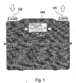
- a conventional mechanical gas meter comprises a gas inlet GB, a gas outlet GK, a measuring chamber with a diaphragm arranged between the gas inlet and the gas outlet, and further elements connected to the diaphragms and to a rotating disk for converting the alternating movement of the diaphragms to rotating movement.
- the rotating disk provides an angular rotation in proportion to the gas volume flowing through the measuring chamber.
- the rotating disk is connected to a mechanical measuring unit MM generally comprising decimal numeric disks connected to each other.
- a drive unit comprising several gears is inserted between the rotating disk and the mechanical measuring unit, the drive unit having a drive ratio that can be set to a predetermined value by selecting the proper gears.
- the gas meter can be calibrated or verified by setting the proper drive ratio.
- the prescribed accuracy of the gas meter can be achieved by calibration.
- the display shows the measuring result - depending on the measuring limits - with a resolution of 0,001 - 0,1 m 3 .
- the electronic elements required for the measurement are integrated in the gas meter housing, together with the mechanical elements, therefore they are not shown in Fig. 1 .
- the additional safety control measuring arrangement as a whole is located inside the housing of the gas meter in a not visible or perceivable manner for the user, it can be practically excluded that the user will try to change or remove it.
- FIG. 2 shows a detail of the internal elements of a possible arrangement of a mechanical gas meter with diaphragm in a simplified schematic form. In this figure only the elements necessary for understanding the measuring arrangement of the invention are shown.
- a vertical axis T1, T2 perpendicular to the drawing plane is connected to each of the measuring chambers of the gas meter with a diaphragm.
- a swivel arm FK1, FK2 is fixed to the upper end of the axis T1, T2.
- the swivel arms FK1, FK2 are connected through swinging arms L1, L2 to a rotating disk FT.
- a mechanical measuring unit (for easier understanding not shown in the drawing) is connected to the rotating axis of the rotating disk FT through the drive with a calibrated/verified transmission ratio.
- the above mechanical structural elements do not perform any kind of movement.
- the vertical axis T1, T2 and the swivel arms FK1, FK2 fixed to them start to perform an alternating swinging movement.
- This swinging movement is converted to rotating movement by swinging arms L1, L2 that drive rotating disk FT in case of gas flow.
- the angular rotation of the rotating disk FT is proportional to the gas volume flown through.
- the safety control measuring arrangement senses the cyclic dislocation of the swivel arms FK1, FK2 performing alternating movement.
- a magnetic transmitter is attached to the swivel arm FK1 and an electromagnetic transmitter is attached in a fixed position relative to the housing in proximity of the magnetic transmitter.
- the magnetic transmitter comprises a permanent magnet M1 and the electromagnetic transmitter comprises reed relays R1, R2.
- the magnet M1 fixed to the swivel arm FK1 approximates alternately the reed relays R1, R2 located in proximity of the end positions thereof.
- the reed relays R1, R2 in proximity of the magnet M1 are actuated and thus its contacts extending into a gas-tight glass housing are closed.
- the reed relays R1, R2 and the magnet M1 are arranged relative to each other so that the magnet M1 alternately reaches a proximal position of reed relays R1 and R2 in the end positions of the rotating arm FK1. Therefore only one of the reed relays R1 of R2 is in an active actuated state, at a time.
- the concurrent actuation of both relays is practically excluded, such a state refers to a relay fault and can be used for error signalization.
- FIG. 3 illustrates the function of the reed relays R1, R2 during continuous gas flow.
- the swivel arms FK1, FK2 fixed to the vertical axis T1, T2 will rotate the rotating disk FT through swinging arms L1, L2 in direction of the arrow.
- the magnet M1 alternately actuates the reed relays R1, R2.
- the active states of the reed relays correspond to positive pulses in the drawing, with a high state corresponding to a closed state of the relay contacts.
- the gas flow is followed by the rotation of the disk, during which the reed relays R1, R2 are operated in a predetermined order, as shown by the upper diagram I of Fig. 3 .
- Eventual functional uncertainty of the reed relays R1, R2 may be eliminated by excluding the transient pulses by using an error correcting bistable circuit, e.g. an RS flip-flop connected to the output of the relays.
- the lower diagram II of Fig. 3 shows the output signal of the error correcting bistable circuit.
- the output state of the flip-flop changes at the starting time of the functioning of the relays R1, R2; that is one of the relays, such as R1 switches the bistable circuit “on” and the other relay, such as R2 switches it “off”.
- Fig. 4 shows a detail of the internal elements of a possible arrangement of a mechanical gas meter with diaphragm in a simplified schematic form similar to Fig. 2 , but in another operating position.
- the safety control measuring arrangement senses the cyclic dislocation of the rotating disk FT, performing rotating movement.
- a magnetic transmitter is attached to the rotating disk FT and electromagnetic transmitters are attached in a fixed position relative to the housing in proximity of the magnetic transmitter.
- the magnetic transmitter comprises a permanent magnet M1 and the electromagnetic transmitter comprises reed relays R1, R2.
- the magnet M1 fixed to the rotating disk FT moves along the reed relays R1, R2 located in a predetermined angular position relative to each other in proximity of the circumference of the rotating disk FT.
- the reed relays R1, R2 enclose an angle of rotation of 180°.
- the reed relays R1, R2 in proximity of the magnet M1 are actuated and thus its contacts enclosed in a gas-tight glass housing are closed.
- the reed relays R1, R2 are located in a most distant location relative to each other for safe operation, thereby excluding the possibility of concurrent operation.
- the concurrent operation of both relays indicates a relay fault and can be used for error signalization.
- FIG. 5 illustrates the function of the reed relays R1, R2 during continuous gas flow.
- the swivel arms FK1, FK2 fixed to the vertical axis T1, T2 will rotate the rotating disk FT through swinging arms L1, L2 in direction of the arrow.
- the magnet M1 alternately actuates the reed relays R1, R2.
- the active states of the reed relays correspond to positive pulses in the drawing, with a high state corresponding to a closed state of the relay contacts.
- the gas flow is followed by the rotation of the disk, during which the reed relays R1, R2 are operated in a predetermined order, as clearly seen in Fig. 5 .
- Eventual functional uncertainty of the reed relays R1, R2 may be eliminated by excluding the transient pulses by using an error correcting bistable circuit, e.g. an RS flip-flop connected to the output of the relays.
- the lower diagram II of Fig. 5 shows the output signal of the error correcting bistable circuit. If the change of the RS flip-flop is triggered by the rising edge of the control signal, the output state of the flip-flop changes at the starting time of the functioning of the relays R1, R2; that is one of the relays, such as R1 switches the bistable circuit "on” and the other relay, such as R2 switches it "off".
- Fig. 6 shows in a simplified schematic form, the valves of the measuring chambers beside (or under) the internal structural elements of the mechanical gas meter with a diaphragm already discussed in detail above.
- the safety control measuring arrangement senses the cyclic dislocation of the valve of the measuring chamber MK1, performing alternating movement.
- a magnetic transmitter is attached to the valve of the measuring chamber MK1, and an electromagnetic transmitters are attached in a fixed position relative to the housing in proximity of the magnetic transmitter.
- the magnetic transmitter comprises a permanent magnet M1 and the electromagnetic transmitters comprise reed relays R1, R2.
- the magnet M1 fixed to the valve of the measuring chamber MK1 approximates alternately the reed relays R1, R2 located in proximity of the end positions thereof.
- the reed relays R1, R2 in proximity of the magnet M1 are actuated and thus its contacts enclosed in a gas-tight glass housing are closed.
- the reed relays R1, R2 are located in a most distant location relative to each other for safe operation, thereby excluding the possibility of concurrent operation.
- the concurrent operation of both relays indicates a relay fault and can be used for error signalization:
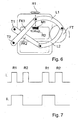
- FIG. 7 illustrates the function of the reed relays R1, R2 during continuous gas flow.
- the swivel arms FK1, FK2 fixed to the vertical axis T1, T2 will rotate the rotating disk FT through swinging arms L1, L2 in direction of the arrow.
- the magnet M1 alternately actuates the reed relays R1, R2.
- the active states of the reed relays correspond to positive pulses in the drawing, with a high state corresponding to a closed state of the relay contacts.
- Fig. 7 The gas flow is followed by the rotation of the disk, during which the reed relays R1, R2 are operated in a predetermined order, as clearly seen in Fig. 7 .
- Eventual functional uncertainty of the reed relays R1, R2 may be eliminated by excluding the transient pulses by using an error correcting bistable circuit, e.g. an RS flip-flop connected to the output of the relays.
- the lower diagram II of Fig. 7 shows the output signal of the error correcting bistable circuit.
- the output state of the flip-flop changes at the starting time of the functioning of the relays R1, R2; that is one of the relays, such as R1 switches the bistable circuit “on” and the other relay, such as R2 switches it "off".
- Fig. 8 a schematic block diagram of the electronic control and processing unit used in the safety control measuring arrangement according to the invention.
- the output of the dislocation sensor comprising the magnet M1 and the reed relays R1, R2 already discussed in detail above, is connected to an input circuit BA of a control and processing unit.
- the input circuit BA comprises preferably an error correcting bistable circuit, such as an RS flip-flop, as already discussed in detail above.
- the output of the input circuit BA is connected to a suitable input of a microcontroller MK.
- the input circuit BA performs the required isolation, matching and conversion of the signal.
- the microcontroller MK comprises internally a data storage AT and a program storage PT. It is also possible to attach an external data storage KAT, in order to extend the data and/or program storing capacity of the microcontroller MK.
- the clock generator OG provides the clock signals required by the microcontroller MK and the time base signal for measuring the time.
- the time and date values associated with the individual measuring results is determined by the microcontroller MK during execution of an internally stored program.
- the radio transmitter receiver unit RAV provides for the reading of the measuring results. The reading of the data requires of course an external radio transmitter receiver unit not shown in the drawing, that enables the reading of the measuring results, the identification data of the meter for an authorized person.
- the measuring values determined during calibration that is the volume of gas flowing through the apparatus during one cycle, has to be fed into the control counter. Beside the measuring values, other data, such as actual date, time, name of the consumer, serial number of the meter, etc. may be added.
- the power supply of the electronic control and processing unit can be accomplished by using a small size and high capacity E battery.
- the capacity of the E battery has to be chosen such that the power supply of the electronic components can be guaranteed without replacement for at least ten years.
- the use safety control measuring arrangement of the invention enables the safety control of the mechanical gas meters. On the basis of the measuring values determined electronically it is possible to control the readings of the mechanical counter and therefore it is possible to detect a failure or a user manipulation.
Landscapes
- Physics & Mathematics (AREA)
- Fluid Mechanics (AREA)
- General Physics & Mathematics (AREA)
- Measuring Volume Flow (AREA)
Applications Claiming Priority (1)
| Application Number | Priority Date | Filing Date | Title |
|---|---|---|---|
| HU0700754A HUP0700754A2 (en) | 2007-11-26 | 2007-11-26 | Electronic arrangement of safety measuremen for mechanical diaphragm type gas meter |
Publications (2)
| Publication Number | Publication Date |
|---|---|
| EP2063234A2 true EP2063234A2 (de) | 2009-05-27 |
| EP2063234A3 EP2063234A3 (de) | 2010-06-16 |
Family
ID=89987889
Family Applications (1)
| Application Number | Title | Priority Date | Filing Date |
|---|---|---|---|
| EP08020483A Withdrawn EP2063234A3 (de) | 2007-11-26 | 2008-11-26 | Elektronisches Sicherheitsmessmodul für mechanische Gasmesser mit Membran |
Country Status (2)
| Country | Link |
|---|---|
| EP (1) | EP2063234A3 (de) |
| HU (1) | HUP0700754A2 (de) |
Cited By (5)
| Publication number | Priority date | Publication date | Assignee | Title |
|---|---|---|---|---|
| EP2249133A1 (de) * | 2009-05-07 | 2010-11-10 | Actaris Gaszählerbau GmbH | Gasmessgerät |
| JP2015232511A (ja) * | 2014-06-10 | 2015-12-24 | 株式会社竹中製作所 | 電子計量式ガスメータ |
| JP2016085196A (ja) * | 2014-10-29 | 2016-05-19 | パナソニックIpマネジメント株式会社 | 流量計測装置 |
| JP2017191061A (ja) * | 2016-04-15 | 2017-10-19 | 愛知時計電機株式会社 | 膜式ガスメーター及びその製造方法 |
| CN109632031A (zh) * | 2018-12-18 | 2019-04-16 | 上海飞奥燃气设备有限公司 | 一种带脉冲输出防干扰的机械模式燃气表 |
Citations (5)
| Publication number | Priority date | Publication date | Assignee | Title |
|---|---|---|---|---|
| US4565090A (en) | 1983-10-17 | 1986-01-21 | Motohiro Gotanda | Detection device for detecting and indicating operation of a gas meter |
| US4848148A (en) | 1988-06-24 | 1989-07-18 | American Meter Company | Cyclic motion detection arrangement |
| JPH11166848A (ja) * | 1997-12-04 | 1999-06-22 | Toyo Keiki Kk | 流量計 |
| JPH11173900A (ja) * | 1997-12-09 | 1999-07-02 | Osaka Gas Co Ltd | 発信器を用いる検出装置 |
| US6269829B1 (en) | 2000-09-29 | 2001-08-07 | Industrial Technology Research Institute | Integrated gas meter |
Family Cites Families (4)
| Publication number | Priority date | Publication date | Assignee | Title |
|---|---|---|---|---|
| GB2242273B (en) * | 1990-03-20 | 1994-01-12 | Smith Meters Ltd | Dry gas meter |
| US5421201A (en) * | 1994-06-27 | 1995-06-06 | Pellerin, Jr.; William J. | Adapter for connecting an encoder remote transmitter to a gas meter |
| EP0801291B1 (de) * | 1996-04-12 | 2004-03-03 | Hans-Holger Körner | Verbrauchszähler mit magnetischem Impulsgeber |
| WO2006035888A1 (ja) * | 2004-09-29 | 2006-04-06 | Matsushita Electric Industrial Co., Ltd. | 流量計測装置 |
-
2007
- 2007-11-26 HU HU0700754A patent/HUP0700754A2/hu unknown
-
2008
- 2008-11-26 EP EP08020483A patent/EP2063234A3/de not_active Withdrawn
Patent Citations (5)
| Publication number | Priority date | Publication date | Assignee | Title |
|---|---|---|---|---|
| US4565090A (en) | 1983-10-17 | 1986-01-21 | Motohiro Gotanda | Detection device for detecting and indicating operation of a gas meter |
| US4848148A (en) | 1988-06-24 | 1989-07-18 | American Meter Company | Cyclic motion detection arrangement |
| JPH11166848A (ja) * | 1997-12-04 | 1999-06-22 | Toyo Keiki Kk | 流量計 |
| JPH11173900A (ja) * | 1997-12-09 | 1999-07-02 | Osaka Gas Co Ltd | 発信器を用いる検出装置 |
| US6269829B1 (en) | 2000-09-29 | 2001-08-07 | Industrial Technology Research Institute | Integrated gas meter |
Cited By (5)
| Publication number | Priority date | Publication date | Assignee | Title |
|---|---|---|---|---|
| EP2249133A1 (de) * | 2009-05-07 | 2010-11-10 | Actaris Gaszählerbau GmbH | Gasmessgerät |
| JP2015232511A (ja) * | 2014-06-10 | 2015-12-24 | 株式会社竹中製作所 | 電子計量式ガスメータ |
| JP2016085196A (ja) * | 2014-10-29 | 2016-05-19 | パナソニックIpマネジメント株式会社 | 流量計測装置 |
| JP2017191061A (ja) * | 2016-04-15 | 2017-10-19 | 愛知時計電機株式会社 | 膜式ガスメーター及びその製造方法 |
| CN109632031A (zh) * | 2018-12-18 | 2019-04-16 | 上海飞奥燃气设备有限公司 | 一种带脉冲输出防干扰的机械模式燃气表 |
Also Published As
| Publication number | Publication date |
|---|---|
| HU0700754D0 (en) | 2008-01-28 |
| EP2063234A3 (de) | 2010-06-16 |
| HUP0700754A2 (en) | 2009-05-28 |
Similar Documents
| Publication | Publication Date | Title |
|---|---|---|
| US6611769B2 (en) | Meter register with programming and data port and meter input resolution factor | |
| US6612188B2 (en) | Self-powered fluid meter | |
| US8448845B2 (en) | Meter register and remote meter reader utilizing a stepper motor | |
| US5056049A (en) | Position Transmitter | |
| CN108426619B (zh) | 高精度双向计量电子水表 | |
| US8878690B2 (en) | AMR transmitter and method using multiple radio messages | |
| EP2063234A2 (de) | Elektronisches Sicherheitsmessmodul für mechanische Gasmesser mit Membran | |
| US20070241930A1 (en) | Automatic Meter-Reading Interface for Fluid Sensing Meters | |
| CN103443832A (zh) | 步进电机测量仪 | |
| RU2337320C1 (ru) | Счетчик для учета воды | |
| EP1692469B1 (de) | Hochauflösende impulszählschnittstelle | |
| EP2249133B1 (de) | Gasmessgerät | |
| CN201772900U (zh) | 一种超声波燃气表 | |
| KR100553579B1 (ko) | 가스계량기용 온압보정기능을 갖는 원격검침장치 | |
| KR200406483Y1 (ko) | 다종 유량계측 표시장치 | |
| JP2002328054A (ja) | ガス流量計測方法とガスメータ | |
| JP2004028958A (ja) | 流量計測装置および流量計測方法 | |
| JPS5841559B2 (ja) | 発電式テレメ−タにおける作動確認方式 | |
| Gavra et al. | Residential smart gas meters | |
| WO2011072625A1 (en) | System for wireless data transfer from measuring instruments | |
| CA2214950C (en) | Electronic gas meter | |
| RU172804U1 (ru) | Устройство измерения расхода жидкости | |
| JPH06229811A (ja) | 積算メータ検針システム | |
| RU2687506C1 (ru) | Электронный блок крыльчатого водосчетчика | |
| RU184812U1 (ru) | Прибор учета расхода природного газа диафрагменного типа с функцией самодиагностики |
Legal Events
| Date | Code | Title | Description |
|---|---|---|---|
| PUAI | Public reference made under article 153(3) epc to a published international application that has entered the european phase |
Free format text: ORIGINAL CODE: 0009012 |
|
| AK | Designated contracting states |
Kind code of ref document: A2 Designated state(s): AT BE BG CH CY CZ DE DK EE ES FI FR GB GR HR HU IE IS IT LI LT LU LV MC MT NL NO PL PT RO SE SI SK TR |
|
| AX | Request for extension of the european patent |
Extension state: AL BA MK RS |
|
| PUAL | Search report despatched |
Free format text: ORIGINAL CODE: 0009013 |
|
| AK | Designated contracting states |
Kind code of ref document: A3 Designated state(s): AT BE BG CH CY CZ DE DK EE ES FI FR GB GR HR HU IE IS IT LI LT LU LV MC MT NL NO PL PT RO SE SI SK TR |
|
| AX | Request for extension of the european patent |
Extension state: AL BA MK RS |
|
| 17P | Request for examination filed |
Effective date: 20100715 |
|
| AKX | Designation fees paid |
Designated state(s): AT BE BG CH CY CZ DE DK EE ES FI FR GB GR HR HU IE IS IT LI LT LU LV MC MT NL NO PL PT RO SE SI SK TR |
|
| 17Q | First examination report despatched |
Effective date: 20160225 |
|
| STAA | Information on the status of an ep patent application or granted ep patent |
Free format text: STATUS: THE APPLICATION IS DEEMED TO BE WITHDRAWN |
|
| 18D | Application deemed to be withdrawn |
Effective date: 20191129 |