EP2066008B1 - Stator d'une machine dynamométrique doté de moyens d'enregistrement de la température - Google Patents
Stator d'une machine dynamométrique doté de moyens d'enregistrement de la température Download PDFInfo
- Publication number
- EP2066008B1 EP2066008B1 EP07023180A EP07023180A EP2066008B1 EP 2066008 B1 EP2066008 B1 EP 2066008B1 EP 07023180 A EP07023180 A EP 07023180A EP 07023180 A EP07023180 A EP 07023180A EP 2066008 B1 EP2066008 B1 EP 2066008B1
- Authority
- EP
- European Patent Office
- Prior art keywords
- stator
- temperature sensor
- sides
- temperature
- slot
- Prior art date
- Legal status (The legal status is an assumption and is not a legal conclusion. Google has not performed a legal analysis and makes no representation as to the accuracy of the status listed.)
- Active
Links
- 238000004804 winding Methods 0.000 claims description 27
- 238000003780 insertion Methods 0.000 claims description 8
- 230000037431 insertion Effects 0.000 claims description 8
- 238000005470 impregnation Methods 0.000 claims description 3
- 238000004519 manufacturing process Methods 0.000 claims description 3
- 239000011521 glass Substances 0.000 claims description 2
- 229920003223 poly(pyromellitimide-1,4-diphenyl ether) Polymers 0.000 claims 1
- 238000009434 installation Methods 0.000 description 3
- 238000012544 monitoring process Methods 0.000 description 3
- 230000004323 axial length Effects 0.000 description 2
- 238000001816 cooling Methods 0.000 description 2
- 238000001514 detection method Methods 0.000 description 2
- RYGMFSIKBFXOCR-UHFFFAOYSA-N Copper Chemical compound [Cu] RYGMFSIKBFXOCR-UHFFFAOYSA-N 0.000 description 1
- 238000004026 adhesive bonding Methods 0.000 description 1
- 230000002411 adverse Effects 0.000 description 1
- 239000012876 carrier material Substances 0.000 description 1
- 238000006243 chemical reaction Methods 0.000 description 1
- 230000001427 coherent effect Effects 0.000 description 1
- 238000005094 computer simulation Methods 0.000 description 1
- 229910052802 copper Inorganic materials 0.000 description 1
- 239000010949 copper Substances 0.000 description 1
- 230000008878 coupling Effects 0.000 description 1
- 238000010168 coupling process Methods 0.000 description 1
- 238000005859 coupling reaction Methods 0.000 description 1
- 238000009413 insulation Methods 0.000 description 1
- 239000007788 liquid Substances 0.000 description 1
- 238000000034 method Methods 0.000 description 1
- 238000004080 punching Methods 0.000 description 1
- 239000011347 resin Substances 0.000 description 1
- 229920005989 resin Polymers 0.000 description 1
- 230000007704 transition Effects 0.000 description 1
Images
Classifications
-
- H—ELECTRICITY
- H02—GENERATION; CONVERSION OR DISTRIBUTION OF ELECTRIC POWER
- H02K—DYNAMO-ELECTRIC MACHINES
- H02K11/00—Structural association of dynamo-electric machines with electric components or with devices for shielding, monitoring or protection
- H02K11/20—Structural association of dynamo-electric machines with electric components or with devices for shielding, monitoring or protection for measuring, monitoring, testing, protecting or switching
- H02K11/25—Devices for sensing temperature, or actuated thereby
-
- H—ELECTRICITY
- H02—GENERATION; CONVERSION OR DISTRIBUTION OF ELECTRIC POWER
- H02K—DYNAMO-ELECTRIC MACHINES
- H02K3/00—Details of windings
- H02K3/46—Fastening of windings on the stator or rotor structure
- H02K3/52—Fastening salient pole windings or connections thereto
- H02K3/521—Fastening salient pole windings or connections thereto applicable to stators only
- H02K3/522—Fastening salient pole windings or connections thereto applicable to stators only for generally annular cores with salient poles
-
- Y—GENERAL TAGGING OF NEW TECHNOLOGICAL DEVELOPMENTS; GENERAL TAGGING OF CROSS-SECTIONAL TECHNOLOGIES SPANNING OVER SEVERAL SECTIONS OF THE IPC; TECHNICAL SUBJECTS COVERED BY FORMER USPC CROSS-REFERENCE ART COLLECTIONS [XRACs] AND DIGESTS
- Y10—TECHNICAL SUBJECTS COVERED BY FORMER USPC
- Y10T—TECHNICAL SUBJECTS COVERED BY FORMER US CLASSIFICATION
- Y10T29/00—Metal working
- Y10T29/49—Method of mechanical manufacture
- Y10T29/49002—Electrical device making
- Y10T29/49009—Dynamoelectric machine
Definitions
- the invention relates to the stator of a dynamoelectric machine, comprising a winding system which is accommodated in grooves of the stator, wherein means for temperature detection are provided.
- Stators of dynamoelectric machines have a winding system to generate a magnetic field. This winding system is positioned in slots of the stator. The windings of the winding system are current-carrying and due to the losses in turns of the winding system is in the grooves and thus ultimately in the laminated core of the stator, an increased temperature in the stator and adjacent other resources.
- per se cooling method such as air or liquid cooling, the heat loss is removed.
- dynamoelectric machines are temperature-monitored, whereby temperature sensors are attached to the laminated core of the stator or to the winding heads of the arranged in the slots of the stator winding of the dynamoelectric machine.
- the object of the invention is to provide a temperature detection in a stator of a dynamoelectric machine, with which the temperature can be detected in a reliable manner in the grooves of the stator, the assembly is carried out in a simple manner.
- the actual temperature profile within the groove is now detected in the winding system, without computational models, starting from a winding head temperature or from a laminated core temperature of the stator to close the actual temperature back.
- the temperature sensor is always placed in the same position in the groove for all motor types, so that the comparable temperature is always recorded at the comparable measuring point and thus a comparable temperature behavior of the dynamoelectric machine is recorded directly. Adverse variations in the response of the temperature sensor by different measuring points and / or temperature couplings are thus minimized.
- the temperature sensor is located on a carrier strip, which in turn is designed in particular as a phase separator, so that an assembly of a phase separator into a groove ultimately introduces not only the phase separator itself but also the temperature sensor into the groove.
- the temperature sensor is arranged in a further advantageous embodiment such that the temperature sensor is located in a punched out of the carrier material and to fix its position on the carrier strip by at least one layer of Elektroisolierbandes, in particular one Kaptonbandes is created.
- This electrical insulating tape creates or supports at least compliance with the required dielectric strength between the two coil sides in a groove.
- the temperature sensor After impregnation of the stator of the dynamoelectric machine, the temperature sensor is firmly anchored and fixed in place by the inserted prefixing and the gluing carried out with impregnating resin.
- a KTY84 is used as a temperature sensor.
- the carrier strip in particular in a rigid version also allows a simple plug-in mounting of the temperature sensor between the phase spacings so for example one two-layer phase separator, especially in dental coils.
- the insertion depth is limited by the protruding on both sides of the carrier strip temperature sensor, so that the temperature sensor is always very easily mounted in the same position both radially, and axially between the two coil sides of a groove.
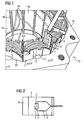
- FIG. 1 shows in perspective a partial view of a stator 10 with a winding system which is formed by tooth coils 12.
- a stator 10 with a winding system which is formed by tooth coils 12.
- the invention itself can also be used in other winding systems, such as distributed winding systems or winded winding systems.
- the stator 10 is constructed in two parts, that is, the stator 10 has a Jochschreiben 19, in which a flat star is used, the teeth of tooth shafts 17 and tooth heads 18 are made.
- Each tooth is constructed from individual sheets 15, but each x-th sheet, in particular every fifth sheet has a continuous web, so that viewed in the circumferential direction, there is a coherent plate 16 in the region of the tooth heads 18. This stabilizes the star during further processing and is sufficient to reduce the groove spread compared to completely closed grooves 20.
- the tooth coils 12, which are advantageously arranged on bobbins 11, are inserted radially from the outside onto the star. Subsequently, the star can be used axially in his Joch Wegen 19 and shed.
- the winding systems of the tooth coil 12 now form winding heads on the end faces of the stator 10.
- Per groove 20 of the stator 19 two coil sides of different tooth coils 12 are present. There is a voltage potential between these coil sides in a groove 20, so that a phase separator 13 is necessary therebetween.
- winding wires of the respective tooth coils 12 can also have a thicker insulation, so that a phase separator does not necessarily have to be used, this, however, possibly reduces the copper fill factor of the groove and enlarges the winding head.
- a carrier strip 6 is now inserted in an advantageous manner according to the invention, which has a temperature sensor 1 and which is placed either between the phase separators 13 of a groove 20 or directly between the coil sides of the coils, in particular the tooth coils 12.
- a phase separator 13 already has such a temperature sensor 1, with the phase separator 13 itself being provided as the carrier strip 6.
- the temperature sensor 1 can additionally be covered by electrical insulating strips 2 with respect to the existing voltage potentials.
- the temperature sensor 1 is connected via a connecting wire 4 and via connecting leads 3 to the outside so as to be able to forward its temperature information.
- the temperature sensor 1 can also be positioned between two carrier strips 6, in particular in the region of a punch-out 5, as described in more detail below.
- a KTY84 is advantageously provided.
- the temperature sensor 1 is provided in a cut-out 5 of the carrier strip 6 in order to further optimize the installation space.
- the temperature sensor 1 is prefixed on the carrier strip 6 always in the same place. Isolated and at the same time fixes the temperature sensor 1 with one or more layers of a temperature-resistant Elektroisolierbandes 2.
- the particular rigid carrier strip 6 now allows easy plug-in mounting of the temperature sensor 1 between the coil sides of a groove 20 and / or between phase separators 13 of the adjacent coil sides of the tooth coils 12 in a groove 20.
- the insertion depth is limited by the protruding on both sides of the carrier strip 6 or carrier plate body, in particular glass body protruding temperature sensor 1.
- the carrier strip 6 clamps between the coil longitudinal sides by the body protruding on both sides of the temperature sensor 1 is supported on the two located in a groove 20 tooth coils.
- the temperature sensor 1 can always be attached at the intended location between the two coil sides.
- the attachment is used in particular for pre-assembly and is by the additional impregnation of the stator 10 further fixed and positioned.
- the temperature sensor 1 vibration proof is positioned very close to the decisive heat source, so that must not be closed by cumbersome conversion method to the actual relevant temperature within the winding in the groove 20.
- the carrier strip 6 is positioned between phase separators 13, it is sufficient if the length of the carrier strip 6 occupies part of the axial length of the stator 10.
- the phase separator 13 must have at least the axial length of the stator 10 in order to have sufficient dielectric strength between the coil sides of a groove 20 can.
- the temperature sensor 1 now detects the temperature of two coils in a groove 20.
- the temperature sensor 1 detects the temperature of two coils in a groove 20.
- the temperature sensor 1 with its connecting wires 4 is connected via a contact 7 with the connecting leads 3.
- These connection leads 3 lead, for example, with other temperature sensors of the dynamoelectric machine or monitoring sensors for vibrations, etc. via a multiplexer to a display or monitoring unit, which can also initiate a shutdown of the dynamoelectric machine depending on the information transmitted.
Landscapes
- Engineering & Computer Science (AREA)
- Microelectronics & Electronic Packaging (AREA)
- Power Engineering (AREA)
Claims (7)
- Stator ( 10 ) d'une machine dynamoélectrique, comprenant un système d'enroulement, notamment des bobines ( 12 ) dentées, qui sont placées dans des encoches ( 20 ) du stator ( 10 ) des côtés différents de bobines se trouvant dans chaque encoche ( 20 ), des têtes d'enroulement étant formées sur les côtés frontaux du stator ( 10 ) et au moins un capteur ( 1 ) de température étant enfiché entre des côtés de bobines se trouvant dans une encoche ( 20 ), caractérisé en ce que la profondeur d'enfichage est limitée par le corps du capteur ( 1 ) de température faisant saillie des deux côtés de la bande ( 6 ) de support ou de la plaquette de support et ainsi le capteur ( 1 ) de température est coincé.
- Stator ( 10 ) suivant la revendication 1, caractérisé en ce que le corps est réalisé sous la forme d'un corps en verre.
- Stator ( 10 ) suivant la revendication 1, caractérisé en ce que la bande ( 6 ) de support forme un séparateur de phase entre les côtés de bobines de l'encoche ( 20 ).
- Stator (10) suivant la revendication 1 ou 3, caractérisé en ce que le capteur ( 1 ) de température est inséré dans une découpe ( 5 ) de la bande ( 6 ) de support correspondant au capteur ( 1 ) de température.
- Stator ( 10 ) suivant l'une des revendications précédentes, caractérisé en ce que la position du capteur ( 1 ) de température est fixée par au moins une position d'une bande ( 2 ) isolante du point de vue électrique, notamment d'une bande en kapton.
- Procédé de fabrication d'un stator ( 10 ) d'une machine dynamoélectrique suivant l'une des revendications précédentes par les stades suivants- paquetage par estampage du paquet de tôles du stator ( 10 ),- insertion de l'enroulement, notamment de bobines (12 ) dentées ou d'un enroulement classique,- enfichage axial d'un capteur ( 1 ) de température se trouvant sur une bande (6) de support ou sur une plaquette de support entre les côtés de bobines d'une encoche ( 20 ) du stator ( 10 ) jusqu'à ce que la profondeur d'enfichage soit limitée par le corps du capteur ( 1 ) de température en saillie des deux côtés de la bande ( 6 ) de support ou de la plaquette de support,- imprégnation du stator ( 10 ).
- Procédé de fabrication d'un stator ( 10 ) suivant la revendication 6, caractérisé en ce qu'on effectue avant l'enfichage axial l'insertion de séparateurs ( 13 ) de phase entre des côtés de bobines différents d'une encoche ( 20 ).
Priority Applications (2)
| Application Number | Priority Date | Filing Date | Title |
|---|---|---|---|
| EP07023180A EP2066008B1 (fr) | 2007-11-29 | 2007-11-29 | Stator d'une machine dynamométrique doté de moyens d'enregistrement de la température |
| US12/324,148 US8022584B2 (en) | 2007-11-29 | 2008-11-26 | Stator of a dynamoelectric machine equipped with temperature detection |
Applications Claiming Priority (1)
| Application Number | Priority Date | Filing Date | Title |
|---|---|---|---|
| EP07023180A EP2066008B1 (fr) | 2007-11-29 | 2007-11-29 | Stator d'une machine dynamométrique doté de moyens d'enregistrement de la température |
Publications (2)
| Publication Number | Publication Date |
|---|---|
| EP2066008A1 EP2066008A1 (fr) | 2009-06-03 |
| EP2066008B1 true EP2066008B1 (fr) | 2011-08-03 |
Family
ID=39323995
Family Applications (1)
| Application Number | Title | Priority Date | Filing Date |
|---|---|---|---|
| EP07023180A Active EP2066008B1 (fr) | 2007-11-29 | 2007-11-29 | Stator d'une machine dynamométrique doté de moyens d'enregistrement de la température |
Country Status (2)
| Country | Link |
|---|---|
| US (1) | US8022584B2 (fr) |
| EP (1) | EP2066008B1 (fr) |
Families Citing this family (29)
| Publication number | Priority date | Publication date | Assignee | Title |
|---|---|---|---|---|
| JP2010259271A (ja) * | 2009-04-27 | 2010-11-11 | Sanyo Electric Co Ltd | 電動モータ及び電動車輌 |
| EP2306622B1 (fr) * | 2009-10-01 | 2013-04-24 | ebm-papst Mulfingen GmbH & Co. KG | Arrangement de stator pour un moteur électrique |
| RU2409884C1 (ru) * | 2010-01-26 | 2011-01-20 | Российская академия сельскохозяйственных наук Государственное научное учреждение Всероссийский научно-исследовательский институт электрификации сельского хозяйства Российской академии сельскохозяйственных наук (ГНУ ВИЭСХ Россельхозакадемии) | Способ эксплуатационного контроля нагрева и защиты электродвигателей |
| JP5693138B2 (ja) * | 2010-10-19 | 2015-04-01 | 三菱重工業株式会社 | 密閉型電動圧縮機 |
| DE102010063581A1 (de) | 2010-10-21 | 2012-04-26 | Robert Bosch Gmbh | Stator einer elektrischen Maschine |
| DE102011085064A1 (de) * | 2011-10-24 | 2013-04-25 | Robert Bosch Gmbh | Sensoranordnung mit mechanischer Vorspannung |
| DE102012104210A1 (de) * | 2011-12-14 | 2013-06-20 | Metabowerke Gmbh | Verfahren und Vorrichtung zur Herstellung eines Stators sowie Stator |
| US20130156071A1 (en) * | 2011-12-16 | 2013-06-20 | Remy Technologies, Llc | Electric Machine Including Insulated Slot Liner With Temperature Sensor |
| JP5916491B2 (ja) * | 2012-04-10 | 2016-05-11 | アイシン精機株式会社 | 回転電機 |
| EP2685607B1 (fr) | 2012-07-09 | 2015-04-01 | Siemens Aktiengesellschaft | Fixation d'aimants permanents sur un rotor |
| JP5971125B2 (ja) * | 2013-01-09 | 2016-08-17 | 株式会社デンソー | 固定子及びそれを備えた回転電機 |
| JP5959715B2 (ja) * | 2013-02-27 | 2016-08-02 | 三菱電機株式会社 | 回転電機 |
| JP6205796B2 (ja) * | 2013-04-03 | 2017-10-04 | アイシン精機株式会社 | 回転電機のステータ |
| US9112396B2 (en) * | 2013-05-07 | 2015-08-18 | Rockwell Automation Technologies, Inc. | Thermostat clamp for electric motors |
| JP2015063266A (ja) * | 2013-09-26 | 2015-04-09 | Ntn株式会社 | 車輪用駆動装置 |
| JP6221804B2 (ja) * | 2014-02-13 | 2017-11-01 | トヨタ自動車株式会社 | 回転電機のステータ |
| JP5738496B1 (ja) * | 2014-05-09 | 2015-06-24 | 三菱電機株式会社 | 回転電機及び回転電機の素線温度計測センサ実装方法 |
| JP6070665B2 (ja) * | 2014-09-30 | 2017-02-01 | トヨタ自動車株式会社 | 回転電機ステータ |
| DE102015110399A1 (de) * | 2015-06-29 | 2016-12-29 | Ebm-Papst Mulfingen Gmbh & Co. Kg | Motortemperaturüberwachung |
| US10833541B2 (en) * | 2016-11-21 | 2020-11-10 | Unison Industries, Inc. | Tooth-wound stator assembly |
| JP6852615B2 (ja) * | 2017-08-01 | 2021-03-31 | 株式会社豊田自動織機 | 回転電機のステータ |
| CN111344934B (zh) | 2017-11-15 | 2022-07-15 | 日立安斯泰莫株式会社 | 旋转电机 |
| DE102018121354A1 (de) * | 2018-08-31 | 2020-03-05 | Valeo Siemens Eautomotive Germany Gmbh | Stator mit einer Temperaturerfassungseinheit für einen Elektromotor |
| DE102019204002A1 (de) | 2019-03-25 | 2020-10-01 | Audi Ag | Verfahren zum Herstellen eines Bauteils |
| DE102019121198A1 (de) * | 2019-04-26 | 2020-10-29 | Schaeffler Technologies AG & Co. KG | Elektrische Maschine |
| DE102019111825A1 (de) * | 2019-05-07 | 2020-11-12 | Schaeffler Technologies AG & Co. KG | Stator für eine elektrische Maschine |
| KR102759865B1 (ko) * | 2019-08-09 | 2025-02-03 | 현대모비스 주식회사 | 구동모터용 환형터미널 유닛의 온도센서 조립구조 및 이의 조립방법 |
| CN114448117B (zh) * | 2020-11-05 | 2023-10-24 | 台达电子工业股份有限公司 | 马达及其发夹形导线定子 |
| JP7728142B2 (ja) * | 2021-10-18 | 2025-08-22 | 株式会社マキタ | 電動作業機 |
Family Cites Families (11)
| Publication number | Priority date | Publication date | Assignee | Title |
|---|---|---|---|---|
| GB737805A (en) * | 1952-12-11 | 1955-10-05 | Vickers Electrical Co Ltd | Improvements in electrical resistance thermometers |
| US2717945A (en) * | 1954-03-30 | 1955-09-13 | Gen Electric | Resistance temperature detector |
| US3130479A (en) * | 1961-03-06 | 1964-04-28 | Gen Motors Corp | Assembly method for overload protector means |
| US3686523A (en) * | 1971-04-21 | 1972-08-22 | Westinghouse Electric Corp | Dynamoelectric machine apparatus, such as brushless exciter for a. c. generator, with flexible tape capacitive means |
| US3842297A (en) * | 1972-04-06 | 1974-10-15 | Smith Corp A O | Receptacle for securing a sensing element within electrical windings |
| US4250419A (en) * | 1973-04-02 | 1981-02-10 | General Electric Company | Holder for overload protector |
| US5032749A (en) * | 1990-01-26 | 1991-07-16 | Magnetek Universal Electric | Electric motor |
| US5831511A (en) * | 1996-07-11 | 1998-11-03 | General Electric Co. | Resistance temperature detector assembly and method of fabricating same |
| JP2921752B2 (ja) * | 1996-09-18 | 1999-07-19 | ファナック株式会社 | 電動機の巻線温度検出素子の取付け方法および取付け具 |
| US6028382A (en) * | 1998-07-14 | 2000-02-22 | Reliance Electrical Industrial Company | Temperature sensing arrangement for the stator core of an electromechanical machine |
| ATE227898T1 (de) * | 2000-05-03 | 2002-11-15 | Leroy Somer Moteurs | Elektrische rotierende maschine mit flusskonzentrationsrotor und um zähne gewickelter stator |
-
2007
- 2007-11-29 EP EP07023180A patent/EP2066008B1/fr active Active
-
2008
- 2008-11-26 US US12/324,148 patent/US8022584B2/en active Active
Also Published As
| Publication number | Publication date |
|---|---|
| US8022584B2 (en) | 2011-09-20 |
| US20090140614A1 (en) | 2009-06-04 |
| EP2066008A1 (fr) | 2009-06-03 |
Similar Documents
| Publication | Publication Date | Title |
|---|---|---|
| EP2066008B1 (fr) | Stator d'une machine dynamométrique doté de moyens d'enregistrement de la température | |
| DE102015106451B4 (de) | Bürstenloser Motor | |
| DE10128769B4 (de) | Elektrischer Motor | |
| EP2182616B1 (fr) | Moteur à courant continu sans balai | |
| EP1617543A2 (fr) | Dispositif à placer des isolants dans les encoches d'un stator | |
| DE2211184C3 (de) | Scheibenanker | |
| DE102019111825A1 (de) | Stator für eine elektrische Maschine | |
| WO2020239545A1 (fr) | Stator d'une machine électrique, doté d'un capteur de température | |
| DE102008059884A1 (de) | Motor für eine elektrische Servolenkungsvorrichtung | |
| DE112016005510T5 (de) | Rotierende elektrische Maschine mit Axialspalt und Verfahren zu deren Herstellung | |
| DE112014004639B4 (de) | Drehende elektrische Maschine und Herstellungsverfahren für diese | |
| DE112011102721B4 (de) | Leiterisolierungsanordnung für eine elektrische Maschine | |
| DE112020000959T5 (de) | Drehende elektrische Maschine, deren Stator und Herstellungsverfahren einer drehenden elektrischen Maschine | |
| DE112008002752T5 (de) | Stator und rotierende elektrische Maschine | |
| DE102013001990A1 (de) | Baugruppenkühlsystem und -Verfahren einer elektrischen Maschine | |
| EP3455921B1 (fr) | Générateur synchrone d'une éolienne à entraînement direct et procédé de fabrication d'un genérateur synchrone | |
| DE112017002040T5 (de) | Gemeinsame Blechkomponente zur Aufnahme von mehrfachen Leitungsgeometrien in einer elektrischen Maschine | |
| DE102006010168A1 (de) | Ankerwicklung, Verfahren zur Herstellung einer Ankerwicklung und schlitzloser Motor | |
| DE102010030877A1 (de) | Steckbarer Polzahn | |
| EP3216113B1 (fr) | Rotor or stator avec tête de bobinage emboîté courte | |
| DE112016004389T5 (de) | Rotierende elektrische maschine und herstellungsverfahren für eine rotierende elektrische maschine | |
| DE102005024653A1 (de) | Stator einer sich drehenden elektrischen Maschine und Herstellungsverfahren des Stators | |
| DE60320165T2 (de) | Drehende elektrische Maschine | |
| DE102022113230A1 (de) | Stator | |
| DE112015006209B4 (de) | Drehelektromaschine |
Legal Events
| Date | Code | Title | Description |
|---|---|---|---|
| PUAI | Public reference made under article 153(3) epc to a published international application that has entered the european phase |
Free format text: ORIGINAL CODE: 0009012 |
|
| AK | Designated contracting states |
Kind code of ref document: A1 Designated state(s): AT BE BG CH CY CZ DE DK EE ES FI FR GB GR HU IE IS IT LI LT LU LV MC MT NL PL PT RO SE SI SK TR |
|
| AX | Request for extension of the european patent |
Extension state: AL BA HR MK RS |
|
| 17P | Request for examination filed |
Effective date: 20090918 |
|
| AKX | Designation fees paid |
Designated state(s): DE |
|
| GRAP | Despatch of communication of intention to grant a patent |
Free format text: ORIGINAL CODE: EPIDOSNIGR1 |
|
| GRAS | Grant fee paid |
Free format text: ORIGINAL CODE: EPIDOSNIGR3 |
|
| GRAA | (expected) grant |
Free format text: ORIGINAL CODE: 0009210 |
|
| AK | Designated contracting states |
Kind code of ref document: B1 Designated state(s): DE |
|
| REG | Reference to a national code |
Ref country code: DE Ref legal event code: R096 Ref document number: 502007007844 Country of ref document: DE Effective date: 20110929 |
|
| PLBE | No opposition filed within time limit |
Free format text: ORIGINAL CODE: 0009261 |
|
| STAA | Information on the status of an ep patent application or granted ep patent |
Free format text: STATUS: NO OPPOSITION FILED WITHIN TIME LIMIT |
|
| 26N | No opposition filed |
Effective date: 20120504 |
|
| REG | Reference to a national code |
Ref country code: DE Ref legal event code: R097 Ref document number: 502007007844 Country of ref document: DE Effective date: 20120504 |
|
| PGFP | Annual fee paid to national office [announced via postgrant information from national office to epo] |
Ref country code: DE Payment date: 20250120 Year of fee payment: 18 |