EP2066578B1 - Frein d'ascenseur à moyeu de frein composite - Google Patents
Frein d'ascenseur à moyeu de frein composite Download PDFInfo
- Publication number
- EP2066578B1 EP2066578B1 EP06803654A EP06803654A EP2066578B1 EP 2066578 B1 EP2066578 B1 EP 2066578B1 EP 06803654 A EP06803654 A EP 06803654A EP 06803654 A EP06803654 A EP 06803654A EP 2066578 B1 EP2066578 B1 EP 2066578B1
- Authority
- EP
- European Patent Office
- Prior art keywords
- rotor
- brake
- hub
- shaft
- metallic
- Prior art date
- Legal status (The legal status is an assumption and is not a legal conclusion. Google has not performed a legal analysis and makes no representation as to the accuracy of the status listed.)
- Active
Links
Images


Classifications
-
- B—PERFORMING OPERATIONS; TRANSPORTING
- B66—HOISTING; LIFTING; HAULING
- B66D—CAPSTANS; WINCHES; TACKLES, e.g. PULLEY BLOCKS; HOISTS
- B66D5/00—Braking or detent devices characterised by application to lifting or hoisting gear, e.g. for controlling the lowering of loads
- B66D5/02—Crane, lift hoist, or winch brakes operating on drums, barrels, or ropes
- B66D5/12—Crane, lift hoist, or winch brakes operating on drums, barrels, or ropes with axial effect
- B66D5/14—Crane, lift hoist, or winch brakes operating on drums, barrels, or ropes with axial effect embodying discs
-
- F—MECHANICAL ENGINEERING; LIGHTING; HEATING; WEAPONS; BLASTING
- F16—ENGINEERING ELEMENTS AND UNITS; GENERAL MEASURES FOR PRODUCING AND MAINTAINING EFFECTIVE FUNCTIONING OF MACHINES OR INSTALLATIONS; THERMAL INSULATION IN GENERAL
- F16D—COUPLINGS FOR TRANSMITTING ROTATION; CLUTCHES; BRAKES
- F16D65/00—Parts or details
- F16D65/02—Braking members; Mounting thereof
- F16D65/12—Discs; Drums for disc brakes
-
- F—MECHANICAL ENGINEERING; LIGHTING; HEATING; WEAPONS; BLASTING
- F16—ENGINEERING ELEMENTS AND UNITS; GENERAL MEASURES FOR PRODUCING AND MAINTAINING EFFECTIVE FUNCTIONING OF MACHINES OR INSTALLATIONS; THERMAL INSULATION IN GENERAL
- F16D—COUPLINGS FOR TRANSMITTING ROTATION; CLUTCHES; BRAKES
- F16D65/00—Parts or details
- F16D65/02—Braking members; Mounting thereof
- F16D2065/13—Parts or details of discs or drums
- F16D2065/1304—Structure
- F16D2065/1316—Structure radially segmented
-
- F—MECHANICAL ENGINEERING; LIGHTING; HEATING; WEAPONS; BLASTING
- F16—ENGINEERING ELEMENTS AND UNITS; GENERAL MEASURES FOR PRODUCING AND MAINTAINING EFFECTIVE FUNCTIONING OF MACHINES OR INSTALLATIONS; THERMAL INSULATION IN GENERAL
- F16D—COUPLINGS FOR TRANSMITTING ROTATION; CLUTCHES; BRAKES
- F16D65/00—Parts or details
- F16D65/02—Braking members; Mounting thereof
- F16D2065/13—Parts or details of discs or drums
- F16D2065/134—Connection
- F16D2065/1356—Connection interlocking
- F16D2065/1368—Connection interlocking with relative movement both radially and axially
-
- F—MECHANICAL ENGINEERING; LIGHTING; HEATING; WEAPONS; BLASTING
- F16—ENGINEERING ELEMENTS AND UNITS; GENERAL MEASURES FOR PRODUCING AND MAINTAINING EFFECTIVE FUNCTIONING OF MACHINES OR INSTALLATIONS; THERMAL INSULATION IN GENERAL
- F16D—COUPLINGS FOR TRANSMITTING ROTATION; CLUTCHES; BRAKES
- F16D2121/00—Type of actuator operation force
- F16D2121/18—Electric or magnetic
- F16D2121/20—Electric or magnetic using electromagnets
- F16D2121/22—Electric or magnetic using electromagnets for releasing a normally applied brake
-
- F—MECHANICAL ENGINEERING; LIGHTING; HEATING; WEAPONS; BLASTING
- F16—ENGINEERING ELEMENTS AND UNITS; GENERAL MEASURES FOR PRODUCING AND MAINTAINING EFFECTIVE FUNCTIONING OF MACHINES OR INSTALLATIONS; THERMAL INSULATION IN GENERAL
- F16D—COUPLINGS FOR TRANSMITTING ROTATION; CLUTCHES; BRAKES
- F16D2200/00—Materials; Production methods therefor
- F16D2200/0004—Materials; Production methods therefor metallic
Definitions
- This invention generally relates to elevator systems and, more particularly to elevator machine brakes.
- Elevator machines such as a gearless machine, typically include a machine shaft rotationally driven by a machine motor.
- a sheave is supported on the machine shaft and rotates with the machine shaft.
- Ropes or belts are typically tracked through the sheave such that the machine motor may rotate the sheave in one direction to lower the cab and rotate the sheave in the opposite direction to raise the cab.
- Some elevator machines typically include a brake having a brake armature that engages a rotor that rotates with the machine shaft to hold the machine shaft and sheave when the cab is at a selected landing.
- Typical metal room include a splined section that engages a splined section of the machine shaft and a flange section that the brake clamps around to resist rotation of the rotor. The rotor slides along the splined section of the machine shaft as the brake clamps and releases the rotor.
- the metal-to-metal contact between the splined section of the rotor and the splined section of the machine shaft during sliding of the rotor often produces noise.
- US 5,631,510 discloses an electric drive with brakes having a brake disk with a plastic hub provided in its bore.
- an elevator brake rotor as defined in claim 1.
- the invention is distinguisched over US 5,631,510 by the characterizing portion of claim 1.
- One example elevator apparatus for use in an elevator machine includes a rotor that is moveable along a rotatable shaft.
- a non-metallic elevator brake hub guides axial movement of the rotor along the shaft
- the non-metallic elevator brake hub is fixed to a flange portion of a rotor.
- the non-metallic elevator brake hub includes a splined hub opening that aligns with a splined rotor opening through the flange portion. The splined openings engage a corresponding splined portion of a shaft.
- Figure 1 illustrates selected portions of an example machine roomless elevator system.
- Figure 2 illustrates selected portions of an example elevator machine having a brake that resists rotation of a motor-driven shaft.
- Figure 3 illustrates selected portions of the brake shown in Figure 2 .
- Figure 4 shows an isolated view of one side of an example rotor having a non-metallic hub.
- Figure 5 illustrates the other side of the rotor shown in Figure 4 .
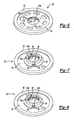
- Figure 6 illustrates an example rotor wherein the splined hub opening is larger than the splined rotor opening.
- Figure 7 illustrates an example rotor having a space between the teeth of the splined rotor opening and the teeth of the splined hub opening.
- Figure 8 illustrates an example rotor having a smaller teeth between the teeth of the splined rotor opening and the teeth of the splined hub opening.
- Figure 1 illustrates selected portions of an example elevator car 6 that moves within a hoistway 8 between landings (not shown).
- the disclosed example illustrates a machine roomless elevator system in which an elevator machine 10 is mounted within the hoistway 8 to move the elevator car 6.
- One issue of concern with in such an arrangement with prior elevator machines is that noise produced by the elevator machine travels through the hoistway and may be heard by passengers in the elevator car.
- the elevator machine 10 of the disclosed examples provides quieter operation, as will be described below. It is to be understood that the disclosed examples also contemplate use in other arrangements besides a machine roomless system.
- FIG. 2 illustrates an example elevator machine 10, such as a gearless machine.
- the elevator machine 10 includes a motor 12 that rotationally drives a machine shaft 14 about an axis 16.
- a sheave 18 rotates with the machine shaft 14.
- An elevator machine brake 20 includes a rotor 22 that is coupled to the machine shaft 14.
- the elevator machine brake 20 selectively applies a braking force to the machine shaft 14 to prevent rotation of the machine shaft 14.
- the machine shaft drives an output shaft on which a sheave is disposed via gears.
- the brake would be applied to the machine shaft, the output shaft, or an intermediate shaft associated with one of the gears in a known manner.
- a controller 23 selectively operates the motor 12 and the elevator machine brake 20 to control movement of the elevator car 6 in the hoistway 8 in a known manner.
- Figure 3 illustrates selected portions of the elevator machine brake 20.
- the elevator machine brake 20 includes an armature 24 for applying a braking force to the rotor 22.
- Bias members 26 bias the armature 24 in a brake-applying direction toward the rotor 22 to clamp the rotor 22 between the armature 24 and a fixed braking surface 28.
- the rotor 22 includes brake linings 30 for wear resistance.
- the brake linings 30 are molded directly on to the rotor 22.
- the rotor 22 includes a flange portion 34 and a non-metallic hub 36 that is rigidly fixed to the flange portion 34.
- the non-metallic hub 36 is secured to the flange portion 34 using fasteners 38 that extend through an annular flange 39 of the non-metallic hub 36 and the flange portion 34.
- the fasteners 38 are evenly spaced about the annular flange 39 to uniformly secure the non-metallic hub 36 and flange portion 34 and to maintain rotational balance of the rotor 22.
- the non-metallic hub 36 is over-molded onto the flange portion 30. In another example, the non-metallic hub 36 is bonded with an adhesive to the flange portion 34. Given this description, one of ordinary skill in the art will recognize other arrangements for securing the non-metallic hub 36 to the flange portion 34.
- the flange portion 34 includes a splined rotor opening 40 and the non-metallic hub 36 includes a splined hub opening 42 that is axially aligned with the splined rotor opening 40.
- the splined rotor opening 40 and the splined hub opening 42 are received onto a splined portion 44 of the shaft 14.
- the splined rotor opening 40 and the splined hub opening 42 each have respective teeth 43a and 43a' that interlock with corresponding teeth 43b of the splined portion 44 such that the three pieces rotate together. Interlocking between the splines functions to transfer torque between the rotor 22 and the machine shaft 14.
- the teeth 43a, 43a', and 43b are shown with a particular geometric cross-sectional shape.
- the teeth 43a and 43a' of the splined openings 40 and 42 match in number and geometry to the teeth 43b of the splined portion 44.
- the teeth 43a, 43a', and 43b are designed with a tolerance to accommodate a difference in thermal expansion between the interlocking pieces, such as from thermal expansion differences between metallic and non-metallic materials. Given this description, one of ordinary skill will recognize alternative shapes to meet their particular needs.
- the splined openings 40 and 42 and teeth 43a and 43a' are formed in a known manner to achieve dimensional equality within a desired tolerance between the openings 40 and 42.
- the splined rotor opening 40 and its teeth 43a are formed by stamping, machining, casting, or other known method.
- the splined hub opening 42 and its teeth 43a' are formed during molding of the non-metallic hub 36.
- the openings 40 and 42 and teeth 43a are formed in a single machining operation to obtain improved dimensional equality and alignment between the openings 40 and 42.
- the openings 40 and 42 are formed in a known manner to achieve a desired dimensional difference such that the non-metallic hub opening 42 is a desired amount larger in size than the rotor opening 40 and the teeth 43a are axially misaligned with the teeth 43a' ( Figure 6 ). This provides some play between the teeth 43a' of the non-metallic hub opening 42 and the splined portion 44 of the machine shaft 14.
- the rotor 22' includes a space 45 between the teeth 43a and 43a'.
- the teeth 43a and 43a' do not extend entirely through the thickness of the rotor 22'.
- the rotor 22" includes relatively smaller teeth 43a" between the teeth 43a and 43a' within the space 45.
- the smaller teeth 43a" serve to reinforce the teeth 43a' of the non-metallic hub 36 during a machining operation to form the teeth 43a and 43a' but do not function to guide movement of the rotor 22".
- various rotor configurations are possible for accommodating, for example, friction, thermal expansion, or other variables associated with a particular design.
- the flange portion 34 is a circular disk made of a non-magnetic material.
- the non-magnetic material is stainless steel, aluminum, or a reinforced plastic composite.
- the thickness of the flange portion 34 is about 4 mm. In another example, the thickness of the flange portion 34 is selected to withstand the entire braking, load from the torque that results during braking.
- the rotor 22 (or alternatively rotor 22' or 22" in the examples hereforth) axially moves along the splined portion 44 of the machine shaft 14 as the armature 24 applies and releases braking force.
- the controller 23 activates an electromagnet 32 to lift the armature 24 and remove the braking force.
- the rotor 22 is spaced apart from the armature 24 and the fixed brake surface 28.
- the armature 24 moves the rotor 22 axially toward the fixed brake surface 28.
- the splined rotor opening 40 and splined hub opening 42 slide along the splined portion 44 of the machine shaft 14.
- the non-metallic hub 36 is of sufficient axial length to guide movement of the rotor 22 by maintaining rotor 22 stability and orientation.
- the axial length L 1 of the non-metallic hub 36 is greater than the axial length L 2 of the flange portion 34 to provide the desired stability and maintain a relative orientation between the rotor 22 and the machine shaft 14.
- the thickness L 2 of the flange portion 34 is selected to withstand the entire braking torque that is applied to the rotor 22.
- the thickness L 1 of the non-metallic hub 36 is chosen such that the overall rotor 22 thickness provides sufficient guidance.
- the total length of the rotor 22, L 1 plus L 2 is of similar total length as previously known entirely metallic rotors, although the lengths could be varied to meet the needs of a particular machine design.
- the non-metallic hub 36 maintains the flange portion 34 in a desired orientation, which in this example is generally perpendicular to the axis 16.
- the term "perpendicular" is not meant to be limiting in a strict geometrical sense.
- the non-metallic hub 36 resists out-of-plane rotation of the rotor 22 (i.e., in a direction transverse to a plane of the rotor 22).
- the flange portion 34 functions to transfer torque load between the rotor 22 and the machine shaft 14, while the non-metallic hub 36 functions to maintain a desired orientation and guide axial movement of the rotor 22.
- the flange portion 34 is of suitable strength for torque transfer during braking and withstands significant deformation under the torque load.
- the non-metallic material of the non-metallic hub 36 is of suitable strength for axially guiding the rotor 22 and is not meant to transfer a large portion of the torque load. By bearing the torque load, the flange portion 34 reduces or eliminates torque load on the non-metallic hub 36.
- the non-metallic hub 36 is formed from a plastic material.
- the non-metallic hub 36 is formed from a stronger material, such as a composite material.
- the composite material is a reinforced plastic. Using a reinforced plastic provides the non-metallic hub 36 with enough strength to transfer at least a portion of the torque load.
- Other non-metallic composite materials are also contemplated.
- non-metallic hub 36 in combination with the flange portion 34 instead of previously known, entirely metallic rotors, provides several benefits.
- One drawback of entirely metallic rotors is that the metal-to-metal contact with the shaft produces noise.
- the non-metallic hub 36 reduces the amount of metal-to-metal contact between the rotor 22 and the shaft 14 compared to previously known entirely metallic rotors. This reduces or eliminates the metal-to-metal noise produced as the rotor 22 slides along the shaft 14.
- the non-metallic hub 36 is made of a noise-dampening material, such as a plastic material, to further reduce the occurrence of noise.
- the rotor 22 and non-metallic hub 36 also provide the further advantage of being easier to make and less expensive than previously known, entirely metallic rotors. Entirely metallic rotors are typically machined to final shape, which is time consuming and wastes material that is removed during machining.
- the flange portion 34 of the rotor 22 is made from a metal plate and requires little or no machining to achieve final shape.
- the non-metallic hub 36 can be molded in a known manner to final or near final shape. This provides the advantage of eliminating the machining and waste material associated with producing entirely metallic rotors.
Landscapes
- Engineering & Computer Science (AREA)
- Mechanical Engineering (AREA)
- General Engineering & Computer Science (AREA)
- Braking Arrangements (AREA)
- Cage And Drive Apparatuses For Elevators (AREA)
Claims (12)
- Rotor de frein comprenant :un arbre pouvant être mis en rotation (14) ayant une portion d'arbre cannelée (44) comprenant des dents d'arbre (43b) s'étendant dans une direction axiale par rapport à l'arbre (14) ;un flasque de rotor (34) qui est déplaçable le long de l'arbre pouvant être mis en rotation (14) ; etune portion de moyeu de frein non métallique (36) guidant un mouvement axial du flasque de rotor (34) le long de l'arbre pouvant être mis en rotation (14), le moyeu non métallique (36) comprenant une ouverture de moyeu (42) ayant une portion de moyeu cannelée pour être mis en prise avec la portion d'arbre cannelée (44), la portion de moyeu cannelée (42) incluant des dents de moyeu (43a') qui s'étendent dans une direction axiale et s'engrènent avec les dents d'arbre (43b) ;caractérisé en ce que :le rotor de frein est un rotor de frein d'ascenseur (22, 22', 22") pour transmettre une force de freinage à l'arbre (14) d'une machinerie d'ascenseur (10) ;le flasque de rotor (34) a une ouverture de rotor (40) qui comprend une portion de rotor cannelée pour être mise en prise avec la portion d'arbre cannelée (44), la portion de rotor cannelée (40) ayant des dents de rotor (43a) s'étendant dans la direction axiale ; etla portion de moyeu de frein non métallique (36) est une portion de moyeu de frein d'ascenseur.
- Rotor de frein selon la revendication 1, dans lequel l'ouverture de moyeu (42) est à peu près égale en taille à l'ouverture de rotor (40) de telle sorte que les dents de rotor (43a) sont axialement alignées avec les dents de moyeu (43a').
- Rotor de frein selon la revendication 1, dans lequel l'ouverture de moyeu (42) a une taille plus grande que l'ouverture de rotor (40) de telle sorte que les dents de rotor (43a) sont axialement désalignées avec les dents de moyeu (43a').
- Rotor de frein selon l'une quelconque des revendications précédentes, dans lequel le flasque de rotor (34) comprend un flasque discoïde qui est fixée à la portion de moyeu de frein d'ascenseur non métallique (36).
- Rotor de frein selon la revendication 4, dans lequel la portion de moyeu de frein d'ascenseur non métallique (36) comprend un flasque de moyeu annulaire (39) s'étendant à partir de la portion cannelée (42) et comprend une pluralité de pièces de fixation (38) qui fixent la portion de moyeu de frein d'ascenseur non métallique (36) au flasque discoïde (34).
- Rotor de frein selon la revendication 5, dans lequel la pluralité de pièces de fixation (38) sont espacées régulièrement autour du flasque annulaire (39).
- Rotor de frein selon la revendication 4, 5 ou 6, dans lequel la portion de moyeu de frein d'ascenseur non métallique (36) comprend une première longueur axiale et le flasque discoïde (34) comprend une seconde longueur axiale qui est inférieure à la première longueur axiale.
- Rotor de frein selon l'une quelconque des revendications 4 à 7, dans lequel le flasque discoïde (34) comprend un matériau sélectionné parmi au moins l'un du groupe constitué par l'acier inoxydable, l'aluminium ou un plastique renforcé.
- Rotor de frein selon l'une quelconque des revendications précédentes, dans lequel la portion de moyeu de frein d'ascenseur non métallique (36) comprend une matière plastique.
- Rotor de frein selon la revendication 9, dans lequel la portion de moyeu de frein d'ascenseur non métallique (36) comprend une matière plastique renforcée.
- Frein (20) comprenant le rotor de frein (22, 22', 22") selon l'une quelconque des revendications précédentes, dans lequel le frein (20) comprend une armature déplaçable axialement (24) qui applique sélectivement une force de freinage au rotor de frein (22, 22', 22").
- Frein (20) selon la revendication 11, comprenant un moteur (12) pour faire tourner l'arbre (14), et un réa (18) qui est mis en rotation par l'arbre (14).
Applications Claiming Priority (1)
| Application Number | Priority Date | Filing Date | Title |
|---|---|---|---|
| PCT/US2006/035963 WO2008033137A1 (fr) | 2006-09-14 | 2006-09-14 | Frein d'ascenseur à moyeu de frein composite |
Publications (2)
| Publication Number | Publication Date |
|---|---|
| EP2066578A1 EP2066578A1 (fr) | 2009-06-10 |
| EP2066578B1 true EP2066578B1 (fr) | 2011-12-28 |
Family
ID=38043053
Family Applications (1)
| Application Number | Title | Priority Date | Filing Date |
|---|---|---|---|
| EP06803654A Active EP2066578B1 (fr) | 2006-09-14 | 2006-09-14 | Frein d'ascenseur à moyeu de frein composite |
Country Status (7)
| Country | Link |
|---|---|
| US (1) | US8052124B2 (fr) |
| EP (1) | EP2066578B1 (fr) |
| JP (1) | JP5203371B2 (fr) |
| CN (1) | CN101668693B (fr) |
| AT (1) | ATE539030T1 (fr) |
| ES (1) | ES2379588T3 (fr) |
| WO (1) | WO2008033137A1 (fr) |
Families Citing this family (10)
| Publication number | Priority date | Publication date | Assignee | Title |
|---|---|---|---|---|
| CN107032220A (zh) * | 2009-06-12 | 2017-08-11 | 奥的斯电梯公司 | 制动器组件 |
| DE202010003882U1 (de) * | 2010-03-19 | 2010-07-22 | Rex Industrie-Produkte Graf Von Rex Gmbh | Bremsrotor |
| WO2011159282A1 (fr) | 2010-06-15 | 2011-12-22 | Otis Elevator Company | Ensemble frein |
| US9365392B2 (en) | 2011-01-19 | 2016-06-14 | Smart Lifts, Llc | System having multiple cabs in an elevator shaft and control method thereof |
| US8925689B2 (en) | 2011-01-19 | 2015-01-06 | Smart Lifts, Llc | System having a plurality of elevator cabs and counterweights that move independently in different sections of a hoistway |
| US8430210B2 (en) | 2011-01-19 | 2013-04-30 | Smart Lifts, Llc | System having multiple cabs in an elevator shaft |
| WO2016092125A1 (fr) * | 2014-12-10 | 2016-06-16 | Otis Elevator Company | Ensemble frein pour un système d'ascenseur |
| DE102016212715A1 (de) * | 2016-07-13 | 2018-01-18 | Robert Bosch Gmbh | Trägertopf für eine Bremsscheibe, Bremsscheibeneinrichtung |
| CN110342381B (zh) * | 2019-06-17 | 2023-12-22 | 菱王电梯有限公司 | 块式制动内转子曳引机 |
| DE102021101058A1 (de) * | 2021-01-19 | 2022-07-21 | Columbus Mckinnon Industrial Products Gmbh | Hebezeug |
Family Cites Families (14)
| Publication number | Priority date | Publication date | Assignee | Title |
|---|---|---|---|---|
| US3675900A (en) * | 1970-03-16 | 1972-07-11 | Byron Jackson Inc | Motion compensating hoist |
| US3727887A (en) * | 1972-01-31 | 1973-04-17 | Eaton Corp | Power hoist with load brake |
| US4046235A (en) * | 1976-04-19 | 1977-09-06 | Western Gear Corporation | Automatic load brake |
| JPS5935739U (ja) * | 1982-08-31 | 1984-03-06 | 小倉クラツチ株式会社 | 負作動形電磁ブレ−キ |
| US4796728A (en) * | 1986-05-05 | 1989-01-10 | Austoft Inc. (U.S.A.) | Brake noise reduction system |
| JPH0735829B2 (ja) * | 1989-08-18 | 1995-04-19 | 株式会社日立製作所 | エレベータ |
| CN2161595Y (zh) * | 1993-03-12 | 1994-04-13 | 南京理工大学 | 集成卷扬机 |
| DE4338570C2 (de) * | 1993-11-05 | 2000-06-08 | Mannesmann Ag | Elektrischer Antrieb mit Bremse, insbesondere für Hebezeuge, Hubeinrichtungen oder positionierende Förderanlagen |
| US6371252B1 (en) * | 2001-08-30 | 2002-04-16 | Shimano Inc. | Bicycle disc brake hub |
| JP2005188703A (ja) * | 2003-12-26 | 2005-07-14 | Shimano Inc | ディスクブレーキロータアセンブリ |
| JP2005308059A (ja) * | 2004-04-20 | 2005-11-04 | Shimano Inc | 自転車用ディスクブレーキロータ組立体 |
| JP4408239B2 (ja) * | 2004-06-03 | 2010-02-03 | 株式会社日立製作所 | 電磁ディスクブレーキ及びそれを備えたエレベーター用巻上機 |
| US7475758B2 (en) * | 2004-06-18 | 2009-01-13 | Hayes Bicycle Group, Inc. | Bicycle disc brake having non-continuous spline surface for quick connection to or release from a wheel hub |
| US7665584B2 (en) * | 2006-04-17 | 2010-02-23 | Shimano Inc. | Disc rotor retaining assembly |
-
2006
- 2006-09-14 EP EP06803654A patent/EP2066578B1/fr active Active
- 2006-09-14 AT AT06803654T patent/ATE539030T1/de active
- 2006-09-14 WO PCT/US2006/035963 patent/WO2008033137A1/fr not_active Ceased
- 2006-09-14 JP JP2009528214A patent/JP5203371B2/ja not_active Expired - Fee Related
- 2006-09-14 US US12/377,694 patent/US8052124B2/en active Active
- 2006-09-14 ES ES06803654T patent/ES2379588T3/es active Active
- 2006-09-14 CN CN2006800558026A patent/CN101668693B/zh active Active
Also Published As
| Publication number | Publication date |
|---|---|
| HK1141777A1 (en) | 2010-11-19 |
| ATE539030T1 (de) | 2012-01-15 |
| ES2379588T3 (es) | 2012-04-27 |
| US8052124B2 (en) | 2011-11-08 |
| CN101668693A (zh) | 2010-03-10 |
| US20100163816A1 (en) | 2010-07-01 |
| CN101668693B (zh) | 2011-12-14 |
| JP5203371B2 (ja) | 2013-06-05 |
| WO2008033137A1 (fr) | 2008-03-20 |
| JP2010503593A (ja) | 2010-02-04 |
| EP2066578A1 (fr) | 2009-06-10 |
Similar Documents
| Publication | Publication Date | Title |
|---|---|---|
| EP0736477B1 (fr) | Moteur d'entraínement pour ascenseur | |
| EP2066578B1 (fr) | Frein d'ascenseur à moyeu de frein composite | |
| EP0545369B1 (fr) | Frein à disque pour tambour d'entraînement d'un ascenseur | |
| US20060151254A1 (en) | Elevator brake | |
| US20030040386A1 (en) | Drive sheave of elevator | |
| US5201821A (en) | Disc brake elevator drive sheave | |
| EP2263962B1 (fr) | Machine d'entraînement pour ascenseur | |
| EP2057091B1 (fr) | Frein de machine élévatrice avec palier intégré et surface de frein | |
| HK1141777B (en) | Elevator brake with composite brake hub | |
| CA2217299A1 (fr) | Entrainement compact pour appareils de levage | |
| WO2003062115A1 (fr) | Frein d'ascenseur | |
| WO2024049388A1 (fr) | Système de traction d'ascenseur intégré monté sur rail | |
| DE29823327U1 (de) | Hebevorrichtung, insbesondere Aufzug, mit einem Elektromotor | |
| EP1845052B1 (fr) | Treuil d'ascenseur | |
| EP4429990A1 (fr) | Système de traction d'ascenseur intégré monté sur rail | |
| WO2008045033A2 (fr) | Frein d'ascenseur | |
| HK1123270B (en) | Winding machine for elevator | |
| HK1137718B (en) | Elevator machine brake with integrated bearing and brake surface | |
| HK1123270A1 (zh) | 电梯用卷扬机 | |
| KR20060096112A (ko) | 엘리베이터용 권상기 |
Legal Events
| Date | Code | Title | Description |
|---|---|---|---|
| PUAI | Public reference made under article 153(3) epc to a published international application that has entered the european phase |
Free format text: ORIGINAL CODE: 0009012 |
|
| 17P | Request for examination filed |
Effective date: 20090414 |
|
| AK | Designated contracting states |
Kind code of ref document: A1 Designated state(s): AT BE BG CH CY CZ DE DK EE ES FI FR GB GR HU IE IS IT LI LT LU LV MC NL PL PT RO SE SI SK TR |
|
| AX | Request for extension of the european patent |
Extension state: AL BA HR MK RS |
|
| RIN1 | Information on inventor provided before grant (corrected) |
Inventor name: SEVILLEJA, JOSE Inventor name: SANCHEZ, ANTONIO Inventor name: MARTIN, JUAN Inventor name: ORONOZ, JUAN, MANUEL Inventor name: AGUADO, JOSE, MIGUEL Inventor name: MONZON, ANDRES |
|
| 17Q | First examination report despatched |
Effective date: 20100201 |
|
| GRAP | Despatch of communication of intention to grant a patent |
Free format text: ORIGINAL CODE: EPIDOSNIGR1 |
|
| RIC1 | Information provided on ipc code assigned before grant |
Ipc: B66D 5/14 20060101AFI20110530BHEP Ipc: F16D 65/14 20060101ALI20110530BHEP Ipc: F16D 65/12 20060101ALI20110530BHEP |
|
| GRAS | Grant fee paid |
Free format text: ORIGINAL CODE: EPIDOSNIGR3 |
|
| GRAA | (expected) grant |
Free format text: ORIGINAL CODE: 0009210 |
|
| AK | Designated contracting states |
Kind code of ref document: B1 Designated state(s): AT BE BG CH CY CZ DE DK EE ES FI FR GB GR HU IE IS IT LI LT LU LV MC NL PL PT RO SE SI SK TR |
|
| DAX | Request for extension of the european patent (deleted) | ||
| RAP1 | Party data changed (applicant data changed or rights of an application transferred) |
Owner name: OTIS ELEVATOR COMPANY |
|
| REG | Reference to a national code |
Ref country code: GB Ref legal event code: FG4D |
|
| REG | Reference to a national code |
Ref country code: CH Ref legal event code: EP |
|
| REG | Reference to a national code |
Ref country code: AT Ref legal event code: REF Ref document number: 539030 Country of ref document: AT Kind code of ref document: T Effective date: 20120115 |
|
| REG | Reference to a national code |
Ref country code: IE Ref legal event code: FG4D |
|
| REG | Reference to a national code |
Ref country code: DE Ref legal event code: R096 Ref document number: 602006026748 Country of ref document: DE Effective date: 20120308 |
|
| REG | Reference to a national code |
Ref country code: NL Ref legal event code: VDEP Effective date: 20111228 |
|
| REG | Reference to a national code |
Ref country code: ES Ref legal event code: FG2A Ref document number: 2379588 Country of ref document: ES Kind code of ref document: T3 Effective date: 20120427 |
|
| PG25 | Lapsed in a contracting state [announced via postgrant information from national office to epo] |
Ref country code: LT Free format text: LAPSE BECAUSE OF FAILURE TO SUBMIT A TRANSLATION OF THE DESCRIPTION OR TO PAY THE FEE WITHIN THE PRESCRIBED TIME-LIMIT Effective date: 20111228 |
|
| LTIE | Lt: invalidation of european patent or patent extension |
Effective date: 20111228 |
|
| PG25 | Lapsed in a contracting state [announced via postgrant information from national office to epo] |
Ref country code: LV Free format text: LAPSE BECAUSE OF FAILURE TO SUBMIT A TRANSLATION OF THE DESCRIPTION OR TO PAY THE FEE WITHIN THE PRESCRIBED TIME-LIMIT Effective date: 20111228 Ref country code: SE Free format text: LAPSE BECAUSE OF FAILURE TO SUBMIT A TRANSLATION OF THE DESCRIPTION OR TO PAY THE FEE WITHIN THE PRESCRIBED TIME-LIMIT Effective date: 20111228 Ref country code: GR Free format text: LAPSE BECAUSE OF FAILURE TO SUBMIT A TRANSLATION OF THE DESCRIPTION OR TO PAY THE FEE WITHIN THE PRESCRIBED TIME-LIMIT Effective date: 20120329 Ref country code: SI Free format text: LAPSE BECAUSE OF FAILURE TO SUBMIT A TRANSLATION OF THE DESCRIPTION OR TO PAY THE FEE WITHIN THE PRESCRIBED TIME-LIMIT Effective date: 20111228 |
|
| PG25 | Lapsed in a contracting state [announced via postgrant information from national office to epo] |
Ref country code: CY Free format text: LAPSE BECAUSE OF FAILURE TO SUBMIT A TRANSLATION OF THE DESCRIPTION OR TO PAY THE FEE WITHIN THE PRESCRIBED TIME-LIMIT Effective date: 20111228 Ref country code: BE Free format text: LAPSE BECAUSE OF FAILURE TO SUBMIT A TRANSLATION OF THE DESCRIPTION OR TO PAY THE FEE WITHIN THE PRESCRIBED TIME-LIMIT Effective date: 20111228 |
|
| PG25 | Lapsed in a contracting state [announced via postgrant information from national office to epo] |
Ref country code: EE Free format text: LAPSE BECAUSE OF FAILURE TO SUBMIT A TRANSLATION OF THE DESCRIPTION OR TO PAY THE FEE WITHIN THE PRESCRIBED TIME-LIMIT Effective date: 20111228 Ref country code: SK Free format text: LAPSE BECAUSE OF FAILURE TO SUBMIT A TRANSLATION OF THE DESCRIPTION OR TO PAY THE FEE WITHIN THE PRESCRIBED TIME-LIMIT Effective date: 20111228 Ref country code: IS Free format text: LAPSE BECAUSE OF FAILURE TO SUBMIT A TRANSLATION OF THE DESCRIPTION OR TO PAY THE FEE WITHIN THE PRESCRIBED TIME-LIMIT Effective date: 20120428 Ref country code: NL Free format text: LAPSE BECAUSE OF FAILURE TO SUBMIT A TRANSLATION OF THE DESCRIPTION OR TO PAY THE FEE WITHIN THE PRESCRIBED TIME-LIMIT Effective date: 20111228 Ref country code: BG Free format text: LAPSE BECAUSE OF FAILURE TO SUBMIT A TRANSLATION OF THE DESCRIPTION OR TO PAY THE FEE WITHIN THE PRESCRIBED TIME-LIMIT Effective date: 20120328 Ref country code: CZ Free format text: LAPSE BECAUSE OF FAILURE TO SUBMIT A TRANSLATION OF THE DESCRIPTION OR TO PAY THE FEE WITHIN THE PRESCRIBED TIME-LIMIT Effective date: 20111228 |
|
| PG25 | Lapsed in a contracting state [announced via postgrant information from national office to epo] |
Ref country code: RO Free format text: LAPSE BECAUSE OF FAILURE TO SUBMIT A TRANSLATION OF THE DESCRIPTION OR TO PAY THE FEE WITHIN THE PRESCRIBED TIME-LIMIT Effective date: 20111228 Ref country code: PL Free format text: LAPSE BECAUSE OF FAILURE TO SUBMIT A TRANSLATION OF THE DESCRIPTION OR TO PAY THE FEE WITHIN THE PRESCRIBED TIME-LIMIT Effective date: 20111228 Ref country code: PT Free format text: LAPSE BECAUSE OF FAILURE TO SUBMIT A TRANSLATION OF THE DESCRIPTION OR TO PAY THE FEE WITHIN THE PRESCRIBED TIME-LIMIT Effective date: 20120430 |
|
| REG | Reference to a national code |
Ref country code: AT Ref legal event code: MK05 Ref document number: 539030 Country of ref document: AT Kind code of ref document: T Effective date: 20111228 |
|
| PG25 | Lapsed in a contracting state [announced via postgrant information from national office to epo] |
Ref country code: DK Free format text: LAPSE BECAUSE OF FAILURE TO SUBMIT A TRANSLATION OF THE DESCRIPTION OR TO PAY THE FEE WITHIN THE PRESCRIBED TIME-LIMIT Effective date: 20111228 |
|
| PLBE | No opposition filed within time limit |
Free format text: ORIGINAL CODE: 0009261 |
|
| STAA | Information on the status of an ep patent application or granted ep patent |
Free format text: STATUS: NO OPPOSITION FILED WITHIN TIME LIMIT |
|
| 26N | No opposition filed |
Effective date: 20121001 |
|
| REG | Reference to a national code |
Ref country code: DE Ref legal event code: R097 Ref document number: 602006026748 Country of ref document: DE Effective date: 20121001 |
|
| PG25 | Lapsed in a contracting state [announced via postgrant information from national office to epo] |
Ref country code: AT Free format text: LAPSE BECAUSE OF FAILURE TO SUBMIT A TRANSLATION OF THE DESCRIPTION OR TO PAY THE FEE WITHIN THE PRESCRIBED TIME-LIMIT Effective date: 20111228 |
|
| PG25 | Lapsed in a contracting state [announced via postgrant information from national office to epo] |
Ref country code: MC Free format text: LAPSE BECAUSE OF NON-PAYMENT OF DUE FEES Effective date: 20120930 |
|
| REG | Reference to a national code |
Ref country code: CH Ref legal event code: PL |
|
| GBPC | Gb: european patent ceased through non-payment of renewal fee |
Effective date: 20120914 |
|
| REG | Reference to a national code |
Ref country code: IE Ref legal event code: MM4A |
|
| PG25 | Lapsed in a contracting state [announced via postgrant information from national office to epo] |
Ref country code: FI Free format text: LAPSE BECAUSE OF FAILURE TO SUBMIT A TRANSLATION OF THE DESCRIPTION OR TO PAY THE FEE WITHIN THE PRESCRIBED TIME-LIMIT Effective date: 20111228 |
|
| PG25 | Lapsed in a contracting state [announced via postgrant information from national office to epo] |
Ref country code: LI Free format text: LAPSE BECAUSE OF NON-PAYMENT OF DUE FEES Effective date: 20120930 Ref country code: IE Free format text: LAPSE BECAUSE OF NON-PAYMENT OF DUE FEES Effective date: 20120914 Ref country code: CH Free format text: LAPSE BECAUSE OF NON-PAYMENT OF DUE FEES Effective date: 20120930 Ref country code: GB Free format text: LAPSE BECAUSE OF NON-PAYMENT OF DUE FEES Effective date: 20120914 |
|
| PG25 | Lapsed in a contracting state [announced via postgrant information from national office to epo] |
Ref country code: TR Free format text: LAPSE BECAUSE OF FAILURE TO SUBMIT A TRANSLATION OF THE DESCRIPTION OR TO PAY THE FEE WITHIN THE PRESCRIBED TIME-LIMIT Effective date: 20111228 |
|
| PG25 | Lapsed in a contracting state [announced via postgrant information from national office to epo] |
Ref country code: LU Free format text: LAPSE BECAUSE OF NON-PAYMENT OF DUE FEES Effective date: 20120914 |
|
| PG25 | Lapsed in a contracting state [announced via postgrant information from national office to epo] |
Ref country code: HU Free format text: LAPSE BECAUSE OF FAILURE TO SUBMIT A TRANSLATION OF THE DESCRIPTION OR TO PAY THE FEE WITHIN THE PRESCRIBED TIME-LIMIT Effective date: 20060914 |
|
| PGFP | Annual fee paid to national office [announced via postgrant information from national office to epo] |
Ref country code: IT Payment date: 20150828 Year of fee payment: 10 |
|
| REG | Reference to a national code |
Ref country code: FR Ref legal event code: PLFP Year of fee payment: 11 |
|
| REG | Reference to a national code |
Ref country code: DE Ref legal event code: R082 Ref document number: 602006026748 Country of ref document: DE Representative=s name: SCHMITT-NILSON SCHRAUD WAIBEL WOHLFROM PATENTA, DE |
|
| REG | Reference to a national code |
Ref country code: FR Ref legal event code: PLFP Year of fee payment: 12 |
|
| PG25 | Lapsed in a contracting state [announced via postgrant information from national office to epo] |
Ref country code: IT Free format text: LAPSE BECAUSE OF NON-PAYMENT OF DUE FEES Effective date: 20160914 |
|
| REG | Reference to a national code |
Ref country code: FR Ref legal event code: PLFP Year of fee payment: 13 |
|
| PGFP | Annual fee paid to national office [announced via postgrant information from national office to epo] |
Ref country code: DE Payment date: 20250820 Year of fee payment: 20 |
|
| PGFP | Annual fee paid to national office [announced via postgrant information from national office to epo] |
Ref country code: FR Payment date: 20250821 Year of fee payment: 20 |
|
| PGFP | Annual fee paid to national office [announced via postgrant information from national office to epo] |
Ref country code: ES Payment date: 20251001 Year of fee payment: 20 |