EP2067691A2 - Cowl structure of vehicle - Google Patents
Cowl structure of vehicle Download PDFInfo
- Publication number
- EP2067691A2 EP2067691A2 EP08021007A EP08021007A EP2067691A2 EP 2067691 A2 EP2067691 A2 EP 2067691A2 EP 08021007 A EP08021007 A EP 08021007A EP 08021007 A EP08021007 A EP 08021007A EP 2067691 A2 EP2067691 A2 EP 2067691A2
- Authority
- EP
- European Patent Office
- Prior art keywords
- vehicle
- cowl
- panel
- wall
- cowl box
- Prior art date
- Legal status (The legal status is an assumption and is not a legal conclusion. Google has not performed a legal analysis and makes no representation as to the accuracy of the status listed.)
- Granted
Links
Images


Classifications
-
- B—PERFORMING OPERATIONS; TRANSPORTING
- B62—LAND VEHICLES FOR TRAVELLING OTHERWISE THAN ON RAILS
- B62D—MOTOR VEHICLES; TRAILERS
- B62D25/00—Superstructure or monocoque structure sub-units; Parts or details thereof not otherwise provided for
- B62D25/08—Front or rear portions
- B62D25/081—Cowls
-
- B—PERFORMING OPERATIONS; TRANSPORTING
- B60—VEHICLES IN GENERAL
- B60H—ARRANGEMENTS OF HEATING, COOLING, VENTILATING OR OTHER AIR-TREATING DEVICES SPECIALLY ADAPTED FOR PASSENGER OR GOODS SPACES OF VEHICLES
- B60H1/00—Heating, cooling or ventilating devices
- B60H1/24—Ventilating devices where the heating or cooling is irrelevant
- B60H1/26—Ventilating openings in vehicle exterior; Ducts for conveying ventilating air
- B60H1/28—Ventilating openings in vehicle exterior; Ducts for conveying ventilating air the openings being situated directly in front of vehicle front window
Definitions
- the present invention relates to a cowl structure of a vehicle such as an automobile.
- Some vehicles include a pair of right and left hood ridge members which are respectively provided to right and left side walls of an engine room, and a cowl box which is provided to a rear wall of the engine room and extends in the vehicle width direction to connect the rear end portions of the respective hood ridge members to each other.
- Japanese Patent Application Publication No. Hei. 5-69858 discloses a structure of a vehicle body for supplying outside air to the inside of the vehicle compartment.
- An outside air introducing port is provided to the front end portion of at least one of the hood ridge members.
- the hood ridge members are connected to both end portions of the cowl box in the vehicle width direction.
- An air supplying port is provided to the rear wall of the cowl box and communicates with the inside of the vehicle compartment.
- the outside air is introduced from the outside air introducing port into the inside of the hood ridge member, and then is supplied through the inside of the cowl box to the vehicle compartment via the air supplying port.
- An object of the present invention is to provide a vehicle cowl structure capable of preventing water leak from an air supplying port.
- An aspect of the present invention is a cowl structure of a vehicle, comprising: a cowl box provided to a vehicle body and extended in a vehicle width direction, the cowl box including: a front wall; a rear wall opposed to the front wall in a vehicle front-rear direction; a bottom wall connecting the front wall with the rear wall; and a support panel which extends frontward from an upper end portion of the rear wall and which supports a lower edge portion of a front windshield panel; a partition panel joined to both the rear wall and the bottom wall inside the cowl box, the partition panel constituting, together with the rear wall and the bottom wall, a hollow member portion extending in the vehicle width direction; an outside air introducing port provided in the cowl box, for introducing air outside the vehicle body into the cowl box outside of the member portion; a communication port provided in the partition panel, for allowing an inside and outside of the member portion to communicate with each other inside the cowl box; and an air supplying port provided in the rear wall at a location spaced upward from the bottom wall, the
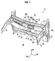
- Fig. 1 in order to illustrate the interior of a cowl structure of a vehicle, a cowl box 10 is depicted with phantom lines and is partly omitted.
- reference letters FR, UP and LH denote frontward/forward, upward and leftward, respectively, with respect to the vehicle body.
- a vehicle compartment 17 and an engine room 18 are separated from each other by a dash panel 5.
- the dash panel 5A is provided on an upper portion thereof with a cowl box 10 extending in the vehicle width direction.
- a partition panel 15 is provided inside the cowl box 10. The partition panel 15 partitions a part of the internal space of the cowl box 10.
- the cowl box 10 has a narrow shape elongated in the vehicle width direction.
- the cowl box 10 supports substantially an entire lower edge portion extending in the vehicle width direction of a front windshield panel 6 ( Fig. 2 ).
- Right and left dash side panels 8, as side panels of the vehicle body, are fixed respectively to the two end portions of the cowl box 10 in the vehicle width direction.
- the dash panels 8 extend frontward from the respective two end portions of the cowl box 10, respectively.
- a hood ridge member (not illustrated) is attached to the outer side surface of the corresponding dash side panel 8.
- the cowl box 10 includes an upper folded piece 5La, a dash upper panel 11, a support panel 12, a cowl lower panel 13 and a cowl upper panel 14.
- the upper folded piece 5La is formed in an upper end portion of a dash lower panel 5L, and substantially horizontally extends frontward from the upper end of the dash lower panel 5L.
- the cowl box 10 in its cross section substantially perpendicular to the vehicle width direction, includes a front wall 10a, a rear wall 10b, a bottom wall 10c and an upper wall 10d.
- the front wall 10a is an inclined wall which constitutes a front side surface of the cowl box 10, and which extends obliquely upward and frontward.
- the rear wall 10b is a wall which is opposed to the front wall 10a in the vehicle front-rear direction, and which extends substantially vertically.
- the bottom wall 10c is a wall with which the lower end of the front wall 10a and the lower end of the rear wall 10b are connected to each other, and which extends in the substantially horizontal direction.
- the upper wall 10d is a wall with which the upper end of the front wall 10a and the upper end of the rear wall 10b are connected to each other, with the lower edge portion of the front windshield panel 6 being interposed in between, and which extends substantially in the horizontal direction.
- the cowl box 10 constitutes a closed cross-section member which has a closed cross-section in a cross-section substantially perpendicular to the vehicle width direction.
- the dash upper panel 11 has a lower folded piece 11b which substantially horizontally extends frontward from the lower end portion of the dash upper panel 11.
- the lower folded piece 11b of the dash upper panel 11 is connected to the upper folded piece 5La of the dash lower panel 5L.
- This dash upper panel 11 constitutes the rear wall 10b of the cowl box 10.
- the cowl lower panel 13 has a substantially L-shape in its cross section substantially perpendicular to the vehicle width direction.
- a rear end portion of a lower side portion 13c of the L-shaped cowl lower panel 13 is connected to the upper folded piece 5La of the dash lower panel 5L. Together with the upper folded piece 5La, the lower side portion 13c constitutes the bottom wall 10c of the cowl box 10.
- a vertical side portion 13b of the L-shaped cowl lower panel 13 extends from the front end of the lower side portion obliquely upward and frontward.
- the vertical side portion 13b is formed to have, at the upper end portion thereof, a front upper end portion 13a which substantially horizontally extends frontward from the upper end of the vertical side portion 13b.
- the support panel 12 as a cantilevered panel, extends frontward from the upper end portion of the dash upper panel 11, in its cross section substantially perpendicular to the vehicle width direction.
- a front tip end portion 12a of the support panel 12 constitutes a free end.
- a rear end portion 12d of the support panel 12 is an inclined wall extending obliquely rearward and upward, and is joined to a flange 11c formed in the upper end portion of the dash upper panel 11.
- a horizontal portion 12c substantially horizontally extends frontward from a front end of the rear end portion 12d. From a front end of the horizontal portion 12c, a middle portion 12M extends obliquely frontward and downward substantially parallel to an inner surface of the front windshield panel 6.
- a front end side of the support panel 12 located in front of the middle portion 12M is an eaves portion 12E which bends downward once and then extends frontward.
- a vertical wall 12b extends obliquely rearward and downward.
- the eaves portion 12E extends obliquely frontward and downward.
- the support panel 12 supports the lower edge portion of the front windshield panel 6.
- the inner surface of the lower edge portion of the front windshield panel 6 is adhered to the upper surface of the middle portion 12M by an adhesive sealing member 16.
- the cowl upper panel 14 connects the front upper end portion 13a of the cowl lower panel 13 to a lowermost edge 6a of the front windshield panel 6.
- the cowl upper panel 14 is formed of a hard synthetic resin.
- the cowl upper panel 14 in its cross section substantially perpendicular to the vehicle width direction, includes: a vertical wall 14c extending obliquely frontward and upward from the upper end portion of the cowl lower panel 13; and a cover portion 14d extending rearward from an upper end of the vertical wall 14c. Together with the vertical side portion 13b of the cowl lower panel 13, the vertical wall 14c constitutes the front wall 10a of the cowl box 10.
- An attachment flange 14F substantially horizontally extending frontward from the lower end of the vertical wall 14c is formed in a front lower end portion 14b of the cowl upper panel 14.
- the attachment flange 14F is fastened to the front upper end portion 13a of the cowl lower panel 13 by use of a fastener.
- a holding part 14H for holding the lowermost edge 6a of the front windshield panel 6 is formed in the rear end portion of the cowl upper panel 14, in other words, the rear end portion 14e of the cover portion 14d.
- the holding part 14H has a substantially U-shape in its cross section substantially perpendicular to the vehicle width direction. Specifically, a slot whose width is substantially equal to the thickness of the lowermost edge 6a of the front windshield panel 6 is formed in the holding part 14H.
- the holding part 14 supports the front windshield panel 6 with the lowermost edge 6a being inserted in the slot.
- An upper rear end portion of the holding part 14H is situated near a tip end portion of the eaves portion 12E of the support panel 12, before, or forward in the vehicle front-rear direction of, and above the tip end portion of the eaves portion 12E.
- the rear end portion 14e of the cover portion 14d is spaced from the front end portion 12a of the support panel 12.
- a downward opening 10e of the upper wall 10d is formed between the rear end portion 14e of the cover portion 14d and the front end portion 12a of the support panel 12.
- the downward opening 10e is located frontward, or forward in the vehicle front-rear direction, of communication ports 15a and 15b provided in the partition panel 15.
- the communication ports 15a and 15b will be described later.
- a weather strip W is provided on the top surface of the front end portion of the cover portion 14d in the present embodiment. This weather strip W is provided to ensure liquid-tightness between the cover portion 14 and a hood panel whose illustration of the hood panel is omitted from the drawings.
- the partition panel 15 extends in the vehicle width direction, and bridges between the right and left dash side panels 8. The two end portions of the partition panel 15 in the vehicle width direction are fixed respectively to the dash side panels 8 ( Fig. 1 ). As shown in Figs. 2 and 3 , the partition panel 15 is arranged inside the cowl box 10, joined to both the rear wall 10b and the bottom wall 10c of the cowl box 10, so as to span between the rear wall 10b and the bottom wall 10c.
- the partition panel 15 has a substantially reversed L-shape in its cross section substantially perpendicular to the vehicle width direction.
- the partition panel 15 has an upper wall 15d which extends substantially horizontally in an upper portion of the partition panel 15.
- the partition panel 15 has a front wall 15c which extends downward from the front end of the upper wall 15d, and which is substantially parallel to the rear wall 10b of the cowl box 10.
- the upper wall 15d is provided in the rear end portion thereof with a flange 15F1 which extends upward from the rear end of the upper wall 15d.
- the front wall 15c is provided in the lower end portion thereof with a flange 15F2 which extends frontward from the lower end of the front wall 15c.
- the flange 15F1 is spot-welded to the front side surface of the dash upper panel 11, at a substantially middle point/level between the flange 11c and the lower folded piece 11b.
- the flange 15F2 connects both the rear end portion of the lower side portion 13c of the cowl lower panel 13 and the front end portion of the upper folded piece 5La of the dash lower panel 5L while the flange 15F2 being held between the rear end portion of the lower side portion 13c and the front end portion of the upper folded piece 5La.
- the partition panel 15 together with the rear wall 10b and the bottom wall 10c of the cowl box 10, constitutes a hollow member portion 19 which extends in the vehicle width direction and has a substantially rectangular cross-section.
- the member portion 19 communicates with the inside of the hood ridge members (not illustrated) attached to the respective outer side surfaces of the dash side panels 8. Specifically, as shown in Fig. 1 , openings 8a are respectively formed in the dash side panels 8 at their portions connected with the member portion 19. Through each opening 8a, the inside of the member portion 19 communicates with the inside of each hood ridge member.
- the opening portions 8a have a substantially rectangular shape. The height of the lower edge of the opening 8a is designed to coincide with the height of the bottom surface of the member portion 19 (the bottom surface of the cowl box 10). When water such as rainwater is accumulated inside the member portion 19, the water is discharged from these openings 8a through the respective hood ridge members to the outside the vehicle.
- an outside air introducing port 14a is provided in the upper wall 10d of the cowl box 10, and the multiple communication ports 15a and 15b (two ports in the present embodiment) are provided in the partition panel 15, as well as an air supplying port 11a is provided in a rear wall 10b of the cowl box 10, which is opposed to the front wall 15c of the partition panel 15.
- the outside air introducing port 14a is formed in a portion of the cover portion 14d of the cowl upper panel 14 constituting the upper wall 10d of the cowl box 10, the portion being covered with the rear edge portion of the hood panel while the hood panel is closed.
- the outside air introducing port 14a introduces the outside air into the space inside the cowl box 10 and outside of the member portion 10.
- the inside and outside of the member portion 19 communicate with the communication ports 15a and 15b.
- Such structure allows air outside the member portion 19 to be introduced into the inside of the member portion 19 through the communication ports 15a and 15b.
- one communication port 15a is a substantially rectangular opening elongated in the vehicle width direction, and is formed in the front wall 15c of the partition panel 15.
- the other communication port 15b is an opening elongated in the vehicle width direction, and is formed in the upper wall 15d.
- the communication port 15a is opposed to the air supplying port 11a in the vehicle front-rear direction.
- the communication port 15a and the air supplying port 11a are positioned in a way that their openings overlap each other, when the openings are viewed from the front of the vehicle. That is to say, projections of the two openings overlap each other if the communication port 15a and the air supplying port 11a are projected onto a plane perpendicular to the vehicle front-rear direction.
- the communication ports 15a and 15b are spaced upward from the bottom wall 10c of the cowl box 10 (the bottom wall of the member portion 19).
- the lower edge of the communication port 15a is located at a predetermined height h1 above the top surface of the bottom wall 10c of the cowl box 10 (the bottom wall of the member portion 19).
- a dike portion 15K is formed under the communication port 15a.
- the dike portion 15K is continuous in the vehicle width direction, and has the predetermined height h1 which is equal to the height from the bottom wall 10c of the cowl box 10 to the lower edge of the communication port 15a.
- the inside of the member portion 19 and the inside of the vehicle compartment 17 communicate with each other through the air supplying port 11a.
- Air inside the member portion 19 is supplied to the inside of the vehicle compartment 17 through the air supplying port 11a.
- the inside of the member portion 19 and the inside of the vehicle compartment 17 communicate with each other through the air supplying port 11a with an air conditioner provided therebetween.
- the air supplying port 11a is provided in a portion of the rear wall 10b of the cowl box 10, which constitutes the member portion 19.
- the air supplying port 11a is provided in a location spaced upward from the bottom wall 10c.
- the lower edge of the air supplying port 11a is located at a predetermined height h2 above the top surface of the bottom wall 10c of the cowl box 10 (the bottom wall of the member portion 19).
- a dike portion 11K is formed under the air supplying port 11a.
- the dike portion 11K is continuous in the vehicle width direction, and has the predetermined height h2 which is equal to the height from the bottom wall 10c of the cowl box 10 to the lower edge of the air supplying port 11a.
- the height h2 of this dike portion 11K is higher than the height h1 of the dike portion 15K of the partition panel 15 (h1 ⁇ h2).
- the air supplying port 11a is connected to a duct (not illustrated) of an air conditioner arranged downstream of the air supplying port 11a.
- This duct is provided with an outside air introducing on-off valve for opening and closing the duct.
- the outside air introducing on-off valve is not illustrated.
- outside air air outside the vehicle body 1 (outside air) flows in a direction indicated by arrows shown in Fig. 3 .
- the outside air is introduced from the outside air introducing port 14a into a space outside of the member portion 19 inside the cowl box 10, then is introduced into the inside of the member portion 19 through the communication ports 15a and 15b, and finally is supplied from the member portion 19 into the vehicle compartment 17 through the air supplying port 11a.
- the communication ports 15a, 15b and the air supplying port 11a overlap each other in the vehicle width direction. Specifically, a range of the communication port 15a in the vehicle width direction between the left and right end edges thereof, a range of the communication port 15b in the vehicle width direction between the right and left end edges thereof, and a range of the air supplying port 11a in the vehicle width direction between the right and left end edges thereof overlap each other.
- This overlapping arrangement allows preventing air from flowing in the vehicle width direction inside the member portion 19 when air is introduced into the inside of the member portion 19 through the communication ports 15a and 15b. Further, this overlapping arrangement prevents the accumulated water such as rainwater from being ruffled inside the member portion 19. Furthermore, this consequence enables to prevent the water from leaking through the air supplying port 11a. Consequently, the present embodiment prevents the water from entering the air conditioner and the vehicle compartment 17 through the air supplying port 11a.
- the communication port 15a and the air supplying port 11a are opposed to each other in the vehicle front-rear direction, air linearly flows from the communication port 15a to the air supplying port 11a.
- This linear air flow more effectively prevents air from flowing in the vehicle width direction inside the member portion 19.
- This positional relation between the communication port 15a and the air supplying port 11a more effectively prevents the accumulated water from being ruffled inside the member portion 19.
- the present embodiment more effectively prevents water from leaking through the air supplying port 11a.
- Supposing the cowl employs a structure which causes outside air to be taken in from an outside air intruding port provided in the front end portion of hood ridge members, and thus to be introduced into the inside of the cowl box via the hood ridge members.
- the outside air thus let in would be heated with the heat generated by the engine installed in the engine room 18 while the outside air is passing each hood ridge member.
- the air conditioner is operated in a cooler mode under such condition, the heated outside air would increase a load on the air conditioner, and would lead to a large consumption of electric power.
- this structure would allow dirt, insects and the like to enter the inside of the hood ridge members.
- the provision of the outside air introducing port 14a in the cowl box 10 produces an effect of effectively preventing the heat from the engine from heating the outside air supplied to the inside of the vehicle chamber 17, in comparison with the above-mentioned structure.
- the present embodiment is capable of controlling the amount of electric power which is consumed by the air conditioner operated in its cooler mode.
- the present embodiment is capable of preventing dirt, insects and the like from entering the inside of each hood ridge member.
- the cowl box 10 includes the cover portion 14d in which the outside air introducing port 14a is formed; the cover portion 14d extends toward the rear of the vehicle from the upper end portion of the front wall 10a, and supports the lowermost edge portion of the front windshield panel 6; the front end portion of the support panel 12 and the rear end portion of the cover portion 14d are spaced from each other; and the opening 10e formed between the front end portion of the support panel 12 and the rear end portion of the cover portion 14d is located frontward of the communication ports 15a and 15b in the vehicle front-rear direction.
- the present embodiment is capable of preventing the falling water from entering the inside of the member portion 19 from the communication ports 15a and 15b, even in a case where water such as rainwater falls into the inside of the cowl box 10 from the opening 10e.
- the support panel 12 in the upper wall 10d of the cowl box 10, is designed to be spaced from the cover portion 14d, and is formed in the cantilever manner. For this reason, even in a case where an external load is applied onto the lower part of the front windshield panel 6 from above, the present embodiment can cause the support panel to produce a reduced reaction force against the external load, and thereby cause the support panel 12 to absorb impact energy efficiently.
- the member portion 19 is formed by including the partition panel 15, the rigidity of the cowl box 10 is reinforced, and therefore the sufficient rigidity in the front part of the vehicle body can be secured.
- the partition panel 15 is suspended between the dash side panels 8 as the right and left vehicle body side panels included in the vehicle body 1, and is fixed to the right and left dash side panels 8. Consequently, the present embodiment reinforces the cowl box more strongly, so that the rigidity of the front part of the vehicle body can be enhanced. This makes the present embodiment capable of preventing abnormal noise such as chattering noise from occurring in the dash panel 5.
- the present embodiment can enhance the cowl's capability of insulating the vehicle compartment 17 from noise including engine noise, which would otherwise enter the vehicle compartment 17 from the front more.
- the cross-section of the partition panel 15 may be shaped in any other form, for instance, in the form of a flat surface instead of the alphabet L.
- the cross-section of the member portion 19 may be shaped like a triangle.
Landscapes
- Engineering & Computer Science (AREA)
- Mechanical Engineering (AREA)
- Chemical & Material Sciences (AREA)
- Combustion & Propulsion (AREA)
- Transportation (AREA)
- Physics & Mathematics (AREA)
- Thermal Sciences (AREA)
- Body Structure For Vehicles (AREA)
Abstract
Description
- The present invention relates to a cowl structure of a vehicle such as an automobile.
- Some vehicles include a pair of right and left hood ridge members which are respectively provided to right and left side walls of an engine room, and a cowl box which is provided to a rear wall of the engine room and extends in the vehicle width direction to connect the rear end portions of the respective hood ridge members to each other.
- Japanese Patent Application Publication No.
Hei. 5-69858 - In the above-described cowl structure, when water such as rainwater enters the cowl box, the water temporarily remains inside the cowl box until being discharged from a drain provided in the cowl box.
- When outside air is supplied to the vehicle compartment, air flows in the vehicle width direction inside the cowl box. Since the cowl box has a narrow shape elongated in the vehicle width direction, the airflow becomes so strong that the water remaining inside the cowl box is ruffled, resulting in that the water leaks from the air supplying port and enters the inside of the vehicle compartment.
- An object of the present invention is to provide a vehicle cowl structure capable of preventing water leak from an air supplying port.
- An aspect of the present invention is a cowl structure of a vehicle, comprising: a cowl box provided to a vehicle body and extended in a vehicle width direction, the cowl box including: a front wall; a rear wall opposed to the front wall in a vehicle front-rear direction; a bottom wall connecting the front wall with the rear wall; and a support panel which extends frontward from an upper end portion of the rear wall and which supports a lower edge portion of a front windshield panel; a partition panel joined to both the rear wall and the bottom wall inside the cowl box, the partition panel constituting, together with the rear wall and the bottom wall, a hollow member portion extending in the vehicle width direction; an outside air introducing port provided in the cowl box, for introducing air outside the vehicle body into the cowl box outside of the member portion; a communication port provided in the partition panel, for allowing an inside and outside of the member portion to communicate with each other inside the cowl box; and an air supplying port provided in the rear wall at a location spaced upward from the bottom wall, the air supplying port allowing the inside of the member portion and an inside of a vehicle compartment to communicate with each other, wherein the communication port and the air supplying port overlap each other in the vehicle width direction.
- The invention will now be described with reference to the accompanying drawings wherein:
-
Fig. 1 is a perspective view showing a front part of a vehicle body including a cowl structure according to an embodiment of the present invention. -
Fig. 2 is a magnified cross-sectional view of the cowl structure taken along the II-II line ofFig. 1 . -
Fig. 3 is a magnified cross-sectional view of the cowl structure taken along the III-III line ofFig. 1 . - A preferred embodiment of the present invention will be described below with reference to the drawings. With regard to
Fig. 1 , in order to illustrate the interior of a cowl structure of a vehicle, acowl box 10 is depicted with phantom lines and is partly omitted. ThroughoutFigs. 1 to 3 , reference letters FR, UP and LH denote frontward/forward, upward and leftward, respectively, with respect to the vehicle body. - As shown in
Figs. 1 to 3 , in a vehicle body 1, avehicle compartment 17 and anengine room 18 are separated from each other by adash panel 5. The dash panel 5A is provided on an upper portion thereof with acowl box 10 extending in the vehicle width direction. Apartition panel 15 is provided inside thecowl box 10. Thepartition panel 15 partitions a part of the internal space of thecowl box 10. - The
cowl box 10 has a narrow shape elongated in the vehicle width direction. Thecowl box 10 supports substantially an entire lower edge portion extending in the vehicle width direction of a front windshield panel 6 (Fig. 2 ). Right and leftdash side panels 8, as side panels of the vehicle body, are fixed respectively to the two end portions of thecowl box 10 in the vehicle width direction. Thedash panels 8 extend frontward from the respective two end portions of thecowl box 10, respectively. A hood ridge member (not illustrated) is attached to the outer side surface of the correspondingdash side panel 8. - As shown in
Figs. 2 and3 , thecowl box 10 includes an upper folded piece 5La, a dashupper panel 11, asupport panel 12, a cowllower panel 13 and a cowlupper panel 14. The upper folded piece 5La is formed in an upper end portion of a dashlower panel 5L, and substantially horizontally extends frontward from the upper end of the dashlower panel 5L. - The
cowl box 10, in its cross section substantially perpendicular to the vehicle width direction, includes afront wall 10a, arear wall 10b, abottom wall 10c and anupper wall 10d. Thefront wall 10a is an inclined wall which constitutes a front side surface of thecowl box 10, and which extends obliquely upward and frontward. Therear wall 10b is a wall which is opposed to thefront wall 10a in the vehicle front-rear direction, and which extends substantially vertically. Thebottom wall 10c is a wall with which the lower end of thefront wall 10a and the lower end of therear wall 10b are connected to each other, and which extends in the substantially horizontal direction. Theupper wall 10d is a wall with which the upper end of thefront wall 10a and the upper end of therear wall 10b are connected to each other, with the lower edge portion of thefront windshield panel 6 being interposed in between, and which extends substantially in the horizontal direction. Together with the lower edge portion of thefront windshield panel 6, thecowl box 10 constitutes a closed cross-section member which has a closed cross-section in a cross-section substantially perpendicular to the vehicle width direction. - The dash
upper panel 11 has a lower foldedpiece 11b which substantially horizontally extends frontward from the lower end portion of the dashupper panel 11. The lower foldedpiece 11b of the dashupper panel 11 is connected to the upper folded piece 5La of the dashlower panel 5L. This dashupper panel 11 constitutes therear wall 10b of thecowl box 10. - The cowl
lower panel 13 has a substantially L-shape in its cross section substantially perpendicular to the vehicle width direction. A rear end portion of alower side portion 13c of the L-shaped cowllower panel 13 is connected to the upper folded piece 5La of the dashlower panel 5L. Together with the upper folded piece 5La, thelower side portion 13c constitutes thebottom wall 10c of thecowl box 10. Avertical side portion 13b of the L-shaped cowllower panel 13 extends from the front end of the lower side portion obliquely upward and frontward. Thevertical side portion 13b is formed to have, at the upper end portion thereof, a frontupper end portion 13a which substantially horizontally extends frontward from the upper end of thevertical side portion 13b. - The
support panel 12, as a cantilevered panel, extends frontward from the upper end portion of the dashupper panel 11, in its cross section substantially perpendicular to the vehicle width direction. A fronttip end portion 12a of thesupport panel 12 constitutes a free end. Arear end portion 12d of thesupport panel 12 is an inclined wall extending obliquely rearward and upward, and is joined to aflange 11c formed in the upper end portion of the dashupper panel 11. Ahorizontal portion 12c substantially horizontally extends frontward from a front end of therear end portion 12d. From a front end of thehorizontal portion 12c, amiddle portion 12M extends obliquely frontward and downward substantially parallel to an inner surface of thefront windshield panel 6. A front end side of thesupport panel 12 located in front of themiddle portion 12M is aneaves portion 12E which bends downward once and then extends frontward. In other words, from the front end of themiddle portion 12M, avertical wall 12b extends obliquely rearward and downward. From a lower end of thevertical wall 12b, theeaves portion 12E extends obliquely frontward and downward. In themiddle portion 12M, thesupport panel 12 supports the lower edge portion of thefront windshield panel 6. The inner surface of the lower edge portion of thefront windshield panel 6 is adhered to the upper surface of themiddle portion 12M by anadhesive sealing member 16. - The cowl
upper panel 14 connects the frontupper end portion 13a of the cowllower panel 13 to alowermost edge 6a of thefront windshield panel 6. The cowlupper panel 14 is formed of a hard synthetic resin. - The cowl
upper panel 14, in its cross section substantially perpendicular to the vehicle width direction, includes: avertical wall 14c extending obliquely frontward and upward from the upper end portion of the cowllower panel 13; and acover portion 14d extending rearward from an upper end of thevertical wall 14c. Together with thevertical side portion 13b of the cowllower panel 13, thevertical wall 14c constitutes thefront wall 10a of thecowl box 10. - An
attachment flange 14F substantially horizontally extending frontward from the lower end of thevertical wall 14c is formed in a frontlower end portion 14b of the cowlupper panel 14. Theattachment flange 14F is fastened to the frontupper end portion 13a of the cowllower panel 13 by use of a fastener. A holdingpart 14H for holding thelowermost edge 6a of thefront windshield panel 6 is formed in the rear end portion of the cowlupper panel 14, in other words, therear end portion 14e of thecover portion 14d. The holdingpart 14H has a substantially U-shape in its cross section substantially perpendicular to the vehicle width direction. Specifically, a slot whose width is substantially equal to the thickness of thelowermost edge 6a of thefront windshield panel 6 is formed in the holdingpart 14H. The holdingpart 14 supports thefront windshield panel 6 with thelowermost edge 6a being inserted in the slot. - An upper rear end portion of the holding
part 14H is situated near a tip end portion of theeaves portion 12E of thesupport panel 12, before, or forward in the vehicle front-rear direction of, and above the tip end portion of theeaves portion 12E. Therear end portion 14e of thecover portion 14d is spaced from thefront end portion 12a of thesupport panel 12. Adownward opening 10e of theupper wall 10d is formed between therear end portion 14e of thecover portion 14d and thefront end portion 12a of thesupport panel 12. Thedownward opening 10e is located frontward, or forward in the vehicle front-rear direction, ofcommunication ports partition panel 15. Thecommunication ports - A weather strip W is provided on the top surface of the front end portion of the
cover portion 14d in the present embodiment. This weather strip W is provided to ensure liquid-tightness between thecover portion 14 and a hood panel whose illustration of the hood panel is omitted from the drawings. - The
partition panel 15 extends in the vehicle width direction, and bridges between the right and leftdash side panels 8. The two end portions of thepartition panel 15 in the vehicle width direction are fixed respectively to the dash side panels 8 (Fig. 1 ). As shown inFigs. 2 and3 , thepartition panel 15 is arranged inside thecowl box 10, joined to both therear wall 10b and thebottom wall 10c of thecowl box 10, so as to span between therear wall 10b and thebottom wall 10c. - The
partition panel 15 has a substantially reversed L-shape in its cross section substantially perpendicular to the vehicle width direction. Thepartition panel 15 has anupper wall 15d which extends substantially horizontally in an upper portion of thepartition panel 15. Thepartition panel 15 has afront wall 15c which extends downward from the front end of theupper wall 15d, and which is substantially parallel to therear wall 10b of thecowl box 10. Theupper wall 15d is provided in the rear end portion thereof with a flange 15F1 which extends upward from the rear end of theupper wall 15d. Thefront wall 15c is provided in the lower end portion thereof with a flange 15F2 which extends frontward from the lower end of thefront wall 15c. The flange 15F1 is spot-welded to the front side surface of the dashupper panel 11, at a substantially middle point/level between theflange 11c and the lower foldedpiece 11b. By spot-welding, the flange 15F2 connects both the rear end portion of thelower side portion 13c of the cowllower panel 13 and the front end portion of the upper folded piece 5La of the dashlower panel 5L while the flange 15F2 being held between the rear end portion of thelower side portion 13c and the front end portion of the upper folded piece 5La. Specifically, together with therear wall 10b and thebottom wall 10c of thecowl box 10, thepartition panel 15 constitutes ahollow member portion 19 which extends in the vehicle width direction and has a substantially rectangular cross-section. - The
member portion 19 communicates with the inside of the hood ridge members (not illustrated) attached to the respective outer side surfaces of thedash side panels 8. Specifically, as shown inFig. 1 ,openings 8a are respectively formed in thedash side panels 8 at their portions connected with themember portion 19. Through eachopening 8a, the inside of themember portion 19 communicates with the inside of each hood ridge member. The openingportions 8a have a substantially rectangular shape. The height of the lower edge of theopening 8a is designed to coincide with the height of the bottom surface of the member portion 19 (the bottom surface of the cowl box 10). When water such as rainwater is accumulated inside themember portion 19, the water is discharged from theseopenings 8a through the respective hood ridge members to the outside the vehicle. - In the present embodiment, for the purpose of supplying air outside the vehicle body 1 (hereinafter referred to as the "outside air") into the
vehicle compartment 17, an outsideair introducing port 14a is provided in theupper wall 10d of thecowl box 10, and themultiple communication ports partition panel 15, as well as anair supplying port 11a is provided in arear wall 10b of thecowl box 10, which is opposed to thefront wall 15c of thepartition panel 15. - The outside
air introducing port 14a is formed in a portion of thecover portion 14d of the cowlupper panel 14 constituting theupper wall 10d of thecowl box 10, the portion being covered with the rear edge portion of the hood panel while the hood panel is closed. The outsideair introducing port 14a introduces the outside air into the space inside thecowl box 10 and outside of themember portion 10. - Inside the
cowl box 10, the inside and outside of themember portion 19 communicate with thecommunication ports member portion 19 to be introduced into the inside of themember portion 19 through thecommunication ports - Out of the two
communication ports communication port 15a is a substantially rectangular opening elongated in the vehicle width direction, and is formed in thefront wall 15c of thepartition panel 15. Theother communication port 15b is an opening elongated in the vehicle width direction, and is formed in theupper wall 15d. Thecommunication port 15a is opposed to theair supplying port 11a in the vehicle front-rear direction. Thecommunication port 15a and theair supplying port 11a are positioned in a way that their openings overlap each other, when the openings are viewed from the front of the vehicle. That is to say, projections of the two openings overlap each other if thecommunication port 15a and theair supplying port 11a are projected onto a plane perpendicular to the vehicle front-rear direction. Thecommunication ports bottom wall 10c of the cowl box 10 (the bottom wall of the member portion 19). The lower edge of thecommunication port 15a is located at a predetermined height h1 above the top surface of thebottom wall 10c of the cowl box 10 (the bottom wall of the member portion 19). In other words, a dike portion 15K is formed under thecommunication port 15a. The dike portion 15K is continuous in the vehicle width direction, and has the predetermined height h1 which is equal to the height from thebottom wall 10c of thecowl box 10 to the lower edge of thecommunication port 15a. - The inside of the
member portion 19 and the inside of thevehicle compartment 17 communicate with each other through theair supplying port 11a. Air inside themember portion 19 is supplied to the inside of thevehicle compartment 17 through theair supplying port 11a. Specifically, the inside of themember portion 19 and the inside of thevehicle compartment 17 communicate with each other through theair supplying port 11a with an air conditioner provided therebetween. Theair supplying port 11a is provided in a portion of therear wall 10b of thecowl box 10, which constitutes themember portion 19. Theair supplying port 11a is provided in a location spaced upward from thebottom wall 10c. That is to say, the lower edge of theair supplying port 11a is located at a predetermined height h2 above the top surface of thebottom wall 10c of the cowl box 10 (the bottom wall of the member portion 19). In other words, a dike portion 11K is formed under theair supplying port 11a. The dike portion 11K is continuous in the vehicle width direction, and has the predetermined height h2 which is equal to the height from thebottom wall 10c of thecowl box 10 to the lower edge of theair supplying port 11a. The height h2 of this dike portion 11K is higher than the height h1 of the dike portion 15K of the partition panel 15 (h1<h2). Theair supplying port 11a is connected to a duct (not illustrated) of an air conditioner arranged downstream of theair supplying port 11a. This duct is provided with an outside air introducing on-off valve for opening and closing the duct. The outside air introducing on-off valve is not illustrated. - Once the vehicle with the foregoing configuration runs with the outside air introducing on-off valve being opened, air outside the vehicle body 1 (outside air) flows in a direction indicated by arrows shown in
Fig. 3 . Specifically, the outside air is introduced from the outsideair introducing port 14a into a space outside of themember portion 19 inside thecowl box 10, then is introduced into the inside of themember portion 19 through thecommunication ports member portion 19 into thevehicle compartment 17 through theair supplying port 11a. - In the case of the present embodiment, the
communication ports air supplying port 11a overlap each other in the vehicle width direction. Specifically, a range of thecommunication port 15a in the vehicle width direction between the left and right end edges thereof, a range of thecommunication port 15b in the vehicle width direction between the right and left end edges thereof, and a range of theair supplying port 11a in the vehicle width direction between the right and left end edges thereof overlap each other. This overlapping arrangement allows preventing air from flowing in the vehicle width direction inside themember portion 19 when air is introduced into the inside of themember portion 19 through thecommunication ports member portion 19. Furthermore, this consequence enables to prevent the water from leaking through theair supplying port 11a. Consequently, the present embodiment prevents the water from entering the air conditioner and thevehicle compartment 17 through theair supplying port 11a. - In addition, in the present embodiment, because the
communication port 15a and theair supplying port 11a are opposed to each other in the vehicle front-rear direction, air linearly flows from thecommunication port 15a to theair supplying port 11a. This linear air flow more effectively prevents air from flowing in the vehicle width direction inside themember portion 19. This positional relation between thecommunication port 15a and theair supplying port 11a more effectively prevents the accumulated water from being ruffled inside themember portion 19. As a consequence, the present embodiment more effectively prevents water from leaking through theair supplying port 11a. - Supposing the cowl employs a structure which causes outside air to be taken in from an outside air intruding port provided in the front end portion of hood ridge members, and thus to be introduced into the inside of the cowl box via the hood ridge members. The outside air thus let in would be heated with the heat generated by the engine installed in the
engine room 18 while the outside air is passing each hood ridge member. When the air conditioner is operated in a cooler mode under such condition, the heated outside air would increase a load on the air conditioner, and would lead to a large consumption of electric power. Moreover, this structure would allow dirt, insects and the like to enter the inside of the hood ridge members. - In contrast, according to the present embodiment, the provision of the outside
air introducing port 14a in thecowl box 10 produces an effect of effectively preventing the heat from the engine from heating the outside air supplied to the inside of thevehicle chamber 17, in comparison with the above-mentioned structure. For this reason, the present embodiment is capable of controlling the amount of electric power which is consumed by the air conditioner operated in its cooler mode. In addition, the present embodiment is capable of preventing dirt, insects and the like from entering the inside of each hood ridge member. - Furthermore, in the present embodiment, the
cowl box 10 includes thecover portion 14d in which the outsideair introducing port 14a is formed; thecover portion 14d extends toward the rear of the vehicle from the upper end portion of thefront wall 10a, and supports the lowermost edge portion of thefront windshield panel 6; the front end portion of thesupport panel 12 and the rear end portion of thecover portion 14d are spaced from each other; and theopening 10e formed between the front end portion of thesupport panel 12 and the rear end portion of thecover portion 14d is located frontward of thecommunication ports opening 10e formed between the front end portion of thesupport panel 12 and the rear end portion of thecover portion 14d is located frontward of thecommunication ports member portion 19 from thecommunication ports cowl box 10 from theopening 10e. - Additionally, in the present embodiment, in the
upper wall 10d of thecowl box 10, thesupport panel 12 is designed to be spaced from thecover portion 14d, and is formed in the cantilever manner. For this reason, even in a case where an external load is applied onto the lower part of thefront windshield panel 6 from above, the present embodiment can cause the support panel to produce a reduced reaction force against the external load, and thereby cause thesupport panel 12 to absorb impact energy efficiently. - On the other hand, in the present embodiment, because the
member portion 19 is formed by including thepartition panel 15, the rigidity of thecowl box 10 is reinforced, and therefore the sufficient rigidity in the front part of the vehicle body can be secured. Furthermore, in the present embodiment, thepartition panel 15 is suspended between thedash side panels 8 as the right and left vehicle body side panels included in the vehicle body 1, and is fixed to the right and leftdash side panels 8. Consequently, the present embodiment reinforces the cowl box more strongly, so that the rigidity of the front part of the vehicle body can be enhanced. This makes the present embodiment capable of preventing abnormal noise such as chattering noise from occurring in thedash panel 5. Moreover, as described above, because thepartition panel 15 is suspended between and fixed to thedash side panels 8 as the right and left vehicle body side panels included in the vehicle body 1, the present embodiment can enhance the cowl's capability of insulating thevehicle compartment 17 from noise including engine noise, which would otherwise enter thevehicle compartment 17 from the front more. - The preferred embodiment described herein is illustrative and not restrictive, and the invention may be practiced or embodied in other ways without departing from the spirit or essential character thereof. For example, the cross-section of the
partition panel 15 may be shaped in any other form, for instance, in the form of a flat surface instead of the alphabet L. As well, the cross-section of themember portion 19 may be shaped like a triangle. The scope of the invention being indicated by the claims, and all variations which come within the meaning of claims are intended to be embraced herein. - The present disclosure relates to subject matters contained in Japanese Patent Application No.
2007-316969, filed on December 7, 2007
Claims (4)
- A cowl structure of a vehicle, comprising:a cowl box (10) provided to a vehicle body (1) and extended in a vehicle width direction, the cowl box (10) including: a front wall (10a); a rear wall (10b) opposed to the front wall (10a) in a vehicle front-rear direction; a bottom wall (10c) connecting the front wall (10a) with the rear wall (10b); and a support panel (12) which extends frontward from an upper end portion of the rear wall (10b) and which supports a lower edge portion of a front windshield panel (6);a partition panel (15) joined to both the rear wall (10b) and the bottom wall (10c) inside the cowl box (10), the partition panel (15) constituting, together with the rear wall (10b) and the bottom wall (10c), a hollow member portion (19) extending in the vehicle width direction;an outside air introducing port (14a) provided in the cowl box (10), for introducing air outside the vehicle body (1) into the cowl box (10) outside of the member portion (19);a communication port (15a, 15b) provided in the partition panel (15), for allowing an inside and outside of the member portion (19) to communicate with each other inside the cowl box (10); andan air supplying port (11a) provided in the rear wall (10b) at a location spaced upward from the bottom wall (10c), the air supplying port (11a) allowing the inside of the member portion (19) and an inside of a vehicle compartment (17) to communicate with each other,wherein the communication port (15a, 15b) and the air supplying port (11a) overlap each other in the vehicle width direction.
- The cowl structure of a vehicle according to claim 1,
wherein the communication port (15a) and the air supplying port (11a) are opposed to each other in the vehicle front-rear direction. - The cowl structure of a vehicle according to claim 1 or 2, wherein
the cowl box (10) further includes a cover portion (14d) in which the outside air introducing port (14a) is formed,
the cover portion (14d) extends rearward from an upper end of the front wall (10a), and supports a lowermost edge portion (6a) of the front windshield panel (6),
a front end portion (12a) of the support panel (12) and a rear end portion (14e) of the cover portion (14d) are spaced from each other, and
an opening (10e) formed between the front end portion (12a) of the support panel (12) and the rear end portion (14e) of the cover portion (14d) is located forward of the communication port (15a, 15b) in the vehicle front-rear direction. - The cowl structure of a vehicle according to any one of claims 1 to 3,
wherein the partition panel (15) is extended between right and left vehicle body side panels (8) of the vehicle body (1), and is fixed to the right and left vehicle body side panels (8).
Applications Claiming Priority (1)
| Application Number | Priority Date | Filing Date | Title |
|---|---|---|---|
| JP2007316969A JP4492689B2 (en) | 2007-12-07 | 2007-12-07 | Car cowl structure |
Publications (3)
| Publication Number | Publication Date |
|---|---|
| EP2067691A2 true EP2067691A2 (en) | 2009-06-10 |
| EP2067691A3 EP2067691A3 (en) | 2009-11-18 |
| EP2067691B1 EP2067691B1 (en) | 2011-09-28 |
Family
ID=40297715
Family Applications (1)
| Application Number | Title | Priority Date | Filing Date |
|---|---|---|---|
| EP08021007A Active EP2067691B1 (en) | 2007-12-07 | 2008-12-03 | Cowl structure of vehicle |
Country Status (4)
| Country | Link |
|---|---|
| US (1) | US7976097B2 (en) |
| EP (1) | EP2067691B1 (en) |
| JP (1) | JP4492689B2 (en) |
| CN (1) | CN101450683B (en) |
Cited By (7)
| Publication number | Priority date | Publication date | Assignee | Title |
|---|---|---|---|---|
| EP2439130A1 (en) * | 2010-10-08 | 2012-04-11 | Eurostyle Systems | Cowl vent grille under a windscreen |
| DE102010053471A1 (en) | 2010-12-04 | 2012-06-06 | Volkswagen Ag | Device for air-conditioning interior part of automobile, has separation wall arranged between front and rear walls, where value of ambient air mass flow and value of air mass stream supplied to air conditioner are adjusted |
| WO2015177433A1 (en) * | 2014-05-20 | 2015-11-26 | Renault S.A.S. | Scoop for a water container built into the dividing wall |
| FR3021905A1 (en) * | 2014-06-10 | 2015-12-11 | Renault Sas | FRESH AIR SUPPLY SYSTEM OF A MOTOR VEHICLE AND METHOD FOR MOUNTING SAID POWER SYSTEM IN THE MOTOR VEHICLE |
| EP3090925A1 (en) * | 2015-05-07 | 2016-11-09 | Renault S.A.S. | Windshield bay cross member for a motor vehicle and associated motor vehicle |
| EP3249946A1 (en) * | 2016-05-27 | 2017-11-29 | Alpine Electronics, Inc. | Vehicle loudspeaker system |
| US12403959B2 (en) * | 2022-03-21 | 2025-09-02 | Subaru Corporation | Vehicle cowl structure |
Families Citing this family (33)
| Publication number | Priority date | Publication date | Assignee | Title |
|---|---|---|---|---|
| US8696049B2 (en) * | 2007-04-05 | 2014-04-15 | Nissan Motor Co., Ltd. | Vehicle body structure |
| DE602008000247D1 (en) * | 2007-09-10 | 2009-12-10 | Honda Motor Co Ltd | Front part construction of a vehicle |
| JP5394759B2 (en) * | 2009-01-23 | 2014-01-22 | 日本プラスト株式会社 | Cowl top cover mounting structure |
| GB2486844B (en) * | 2009-09-01 | 2012-10-10 | Nihon Plast Co Ltd | A cowl-top cover |
| EP2487092B1 (en) * | 2009-10-09 | 2013-11-20 | Honda Motor Co., Ltd. | Structure for front section of vehicle body |
| US8491042B2 (en) * | 2010-09-07 | 2013-07-23 | Ford Global Technologies, Llc | Energy-absorbing cowl structure |
| FR2965529A1 (en) * | 2010-09-30 | 2012-04-06 | Renault Sa | LOWER TRAY OF DEFORMABLE BAY |
| CN101973316B (en) * | 2010-11-22 | 2012-03-28 | 奇瑞汽车股份有限公司 | Front-wall upper cover plate structure |
| EP2479046B1 (en) * | 2011-01-21 | 2015-04-01 | Volvo Car Corporation | Air supply duct |
| DE102011105131A1 (en) * | 2011-06-21 | 2012-12-27 | GM Global Technology Operations LLC (n. d. Gesetzen des Staates Delaware) | Water separation tank for a motor vehicle |
| EP2730486B1 (en) * | 2011-07-04 | 2016-04-27 | Honda Motor Co., Ltd. | Structure for front portion of vehicle |
| US8567851B2 (en) * | 2011-09-23 | 2013-10-29 | Nissan North America, Inc. | Vehicle cowl cover |
| FR2983450B1 (en) * | 2011-12-02 | 2014-05-16 | Renault Sa | MOTOR VEHICLE COMPRISING A TOP TRAVERSE OF AN APRON |
| JP5820485B2 (en) * | 2012-01-11 | 2015-11-24 | 本田技研工業株式会社 | Vehicle front structure |
| KR101338078B1 (en) * | 2012-03-05 | 2013-12-09 | 현대자동차주식회사 | Structure for inflowing the open air for vehicle |
| EP2684718B1 (en) * | 2012-07-12 | 2018-04-11 | Volvo Car Corporation | An air supply arrangement |
| DE102012023655A1 (en) * | 2012-11-28 | 2014-05-28 | GM Global Technology Operations LLC (n. d. Gesetzen des Staates Delaware) | Motor vehicle tray module with seal |
| JP6136350B2 (en) * | 2013-02-22 | 2017-05-31 | スズキ株式会社 | Structure around the cowl top panel |
| DE102013012483A1 (en) * | 2013-07-26 | 2015-01-29 | GM Global Technology Operations LLC (n. d. Gesetzen des Staates Delaware) | Water deflector for the windshield of a motor vehicle |
| US9981697B2 (en) * | 2014-04-03 | 2018-05-29 | Toyota Jidosha Kabushiki Kaisha | Cowl structure for a vehicle |
| DE102015002701A1 (en) * | 2015-03-04 | 2016-09-08 | GM Global Technology Operations LLC (n. d. Ges. d. Staates Delaware) | Service panel for a motor vehicle, water tank for a motor vehicle and motor vehicle |
| US10272743B2 (en) * | 2015-03-25 | 2019-04-30 | Honda Motor Co., Ltd. | Cowl air/water separator drain for automobile |
| JP6636720B2 (en) | 2015-05-18 | 2020-01-29 | トヨタ自動車株式会社 | Cowl structure |
| JP6241463B2 (en) | 2015-08-28 | 2017-12-06 | トヨタ自動車株式会社 | Cowl structure |
| JP6144742B2 (en) * | 2015-09-30 | 2017-06-07 | 株式会社Subaru | Wind noise reduction structure for vehicles |
| DE102015014646A1 (en) * | 2015-11-12 | 2017-05-18 | GM Global Technology Operations LLC (n. d. Gesetzen des Staates Delaware) | Water tank cover for a motor vehicle |
| JP6565889B2 (en) * | 2016-12-19 | 2019-08-28 | トヨタ自動車株式会社 | Vehicle front structure |
| JP6738757B2 (en) * | 2017-03-29 | 2020-08-12 | 株式会社神戸製鋼所 | Vehicle front structure |
| JP6816662B2 (en) * | 2017-06-26 | 2021-01-20 | トヨタ自動車株式会社 | Vehicle front structure |
| JP7651961B2 (en) * | 2021-06-02 | 2025-03-27 | スズキ株式会社 | Cowl top garnish |
| JP7746733B2 (en) * | 2021-08-23 | 2025-10-01 | マツダ株式会社 | Vehicle front structure |
| KR20230103161A (en) * | 2021-12-31 | 2023-07-07 | 현대자동차주식회사 | Front vehicle body structure |
| JP7783101B2 (en) * | 2022-03-21 | 2025-12-09 | 株式会社Subaru | Vehicle cowl structure |
Citations (2)
| Publication number | Priority date | Publication date | Assignee | Title |
|---|---|---|---|---|
| JPH0569858A (en) | 1991-09-12 | 1993-03-23 | Mazda Motor Corp | Front body structure of automobile |
| JP2007316969A (en) | 2006-05-26 | 2007-12-06 | Tohoku Regional Bureau Ministry Of Land Infrastructure & Transport | Concrete quality control method |
Family Cites Families (13)
| Publication number | Priority date | Publication date | Assignee | Title |
|---|---|---|---|---|
| JPS6048385B2 (en) * | 1980-06-13 | 1985-10-26 | マツダ株式会社 | Bumpful structure of automobile cowl ventilation device |
| JPS5914577A (en) * | 1982-07-16 | 1984-01-25 | Nissan Motor Co Ltd | Cowl construction for automobile |
| DE3428293C2 (en) | 1984-08-01 | 1986-07-10 | Adam Opel AG, 6090 Rüsselsheim | Upper cowl outer panel for a motor vehicle |
| JPS6175065A (en) * | 1984-09-18 | 1986-04-17 | Nissan Motor Co Ltd | Dashboard structure of car |
| US4819550A (en) * | 1987-07-28 | 1989-04-11 | Mazda Motor Corporation | Air intake structure of an automobile |
| JP2568733B2 (en) * | 1990-05-28 | 1997-01-08 | 日産自動車株式会社 | Automotive air box structure |
| JP2554189B2 (en) * | 1990-05-30 | 1996-11-13 | 日産自動車株式会社 | Front window panel holding structure for automobiles |
| JPH06278655A (en) * | 1993-03-30 | 1994-10-04 | Nissan Shatai Co Ltd | Air box construction |
| JP3613060B2 (en) * | 1999-03-16 | 2005-01-26 | 日産自動車株式会社 | Outside air introduction structure for automobiles |
| JP3640637B2 (en) * | 2001-12-10 | 2005-04-20 | 本田技研工業株式会社 | Seal structure for vehicle cowl top panel |
| JP4104392B2 (en) * | 2002-07-25 | 2008-06-18 | 日野自動車株式会社 | Structure to prevent water from entering outside air |
| DE10351641B3 (en) * | 2003-11-05 | 2005-02-03 | Daimlerchrysler Ag | Fresh air feeding unit for the cabin of a vehicle comprises a wash plate having a passage region impinged with a secondary air stream and forming a grid-like flat region of the wash plate |
| JP2008074202A (en) * | 2006-09-20 | 2008-04-03 | Mazda Motor Corp | Vehicle front structure |
-
2007
- 2007-12-07 JP JP2007316969A patent/JP4492689B2/en active Active
-
2008
- 2008-11-25 US US12/277,628 patent/US7976097B2/en active Active
- 2008-12-03 EP EP08021007A patent/EP2067691B1/en active Active
- 2008-12-08 CN CN200810178003.9A patent/CN101450683B/en active Active
Patent Citations (2)
| Publication number | Priority date | Publication date | Assignee | Title |
|---|---|---|---|---|
| JPH0569858A (en) | 1991-09-12 | 1993-03-23 | Mazda Motor Corp | Front body structure of automobile |
| JP2007316969A (en) | 2006-05-26 | 2007-12-06 | Tohoku Regional Bureau Ministry Of Land Infrastructure & Transport | Concrete quality control method |
Cited By (13)
| Publication number | Priority date | Publication date | Assignee | Title |
|---|---|---|---|---|
| EP2439130A1 (en) * | 2010-10-08 | 2012-04-11 | Eurostyle Systems | Cowl vent grille under a windscreen |
| FR2965787A1 (en) * | 2010-10-08 | 2012-04-13 | Eurostyle Systems | GRID OF AWNING UNDER WINDSHIELD " |
| DE102010053471A1 (en) | 2010-12-04 | 2012-06-06 | Volkswagen Ag | Device for air-conditioning interior part of automobile, has separation wall arranged between front and rear walls, where value of ambient air mass flow and value of air mass stream supplied to air conditioner are adjusted |
| WO2015177433A1 (en) * | 2014-05-20 | 2015-11-26 | Renault S.A.S. | Scoop for a water container built into the dividing wall |
| FR3021286A1 (en) * | 2014-05-20 | 2015-11-27 | Renault Sas | ECOPE FOR WATER BOX INTEGRATED WITH THE WALL OF SEPARATION |
| US10000166B2 (en) | 2014-05-20 | 2018-06-19 | Renault S.A.S. | Scoop for a water container built into the dividing wall |
| WO2015189506A1 (en) * | 2014-06-10 | 2015-12-17 | Renault S.A.S. | Fresh-air supply system of a motor vehicle and method for mounting said supply system in the motor vehicle |
| FR3021905A1 (en) * | 2014-06-10 | 2015-12-11 | Renault Sas | FRESH AIR SUPPLY SYSTEM OF A MOTOR VEHICLE AND METHOD FOR MOUNTING SAID POWER SYSTEM IN THE MOTOR VEHICLE |
| EP3090925A1 (en) * | 2015-05-07 | 2016-11-09 | Renault S.A.S. | Windshield bay cross member for a motor vehicle and associated motor vehicle |
| FR3035848A1 (en) * | 2015-05-07 | 2016-11-11 | Renault Sa | BUS TRAILER FOR A MOTOR VEHICLE AND ASSOCIATED MOTOR VEHICLE |
| EP3249946A1 (en) * | 2016-05-27 | 2017-11-29 | Alpine Electronics, Inc. | Vehicle loudspeaker system |
| US9963083B2 (en) | 2016-05-27 | 2018-05-08 | Alpine Electronics, Inc. | Vehicle loudspeaker system |
| US12403959B2 (en) * | 2022-03-21 | 2025-09-02 | Subaru Corporation | Vehicle cowl structure |
Also Published As
| Publication number | Publication date |
|---|---|
| EP2067691A3 (en) | 2009-11-18 |
| JP2009137483A (en) | 2009-06-25 |
| CN101450683A (en) | 2009-06-10 |
| US7976097B2 (en) | 2011-07-12 |
| JP4492689B2 (en) | 2010-06-30 |
| US20090146459A1 (en) | 2009-06-11 |
| CN101450683B (en) | 2011-09-21 |
| EP2067691B1 (en) | 2011-09-28 |
Similar Documents
| Publication | Publication Date | Title |
|---|---|---|
| EP2067691B1 (en) | Cowl structure of vehicle | |
| EP2684718B1 (en) | An air supply arrangement | |
| JP6011444B2 (en) | Vehicle front structure | |
| KR20090056425A (en) | Undercover system in car engine room | |
| GB2540854A (en) | Panel arrangement for a motor vehicle | |
| US4962961A (en) | Automobile front body structure | |
| JP2012153184A (en) | Engine air-intake structure | |
| JP4403699B2 (en) | Front body structure of automobile | |
| JP6630975B2 (en) | Body front structure | |
| JP2015085781A (en) | Outside air introduction device for vehicle | |
| JP2008074202A (en) | Vehicle front structure | |
| CN216269546U (en) | Vehicle front structure | |
| JP4943245B2 (en) | Ceiling unit for railway vehicles | |
| JP6697715B2 (en) | Vehicle cowl structure | |
| JP3465581B2 (en) | Automotive outside air introduction device | |
| JP5168759B2 (en) | Cooling air guide structure for automobiles | |
| JP2000153781A (en) | Car front structure | |
| JP5240689B2 (en) | Impact force absorption structure of vehicle cowl louver | |
| JP6279877B2 (en) | Outside air introduction device for vehicle | |
| JP4826261B2 (en) | Deck garnish outside air introduction structure | |
| JP2018131091A (en) | Vehicle cowl structure | |
| JP3135593B2 (en) | Car front body structure | |
| JP6242672B2 (en) | Cowl louver | |
| JP2010095166A (en) | Impact force absorption structure of cowl louver for vehicle | |
| JP6308272B2 (en) | Vehicle cowl structure |
Legal Events
| Date | Code | Title | Description |
|---|---|---|---|
| PUAI | Public reference made under article 153(3) epc to a published international application that has entered the european phase |
Free format text: ORIGINAL CODE: 0009012 |
|
| 17P | Request for examination filed |
Effective date: 20081203 |
|
| AK | Designated contracting states |
Kind code of ref document: A2 Designated state(s): AT BE BG CH CY CZ DE DK EE ES FI FR GB GR HR HU IE IS IT LI LT LU LV MC MT NL NO PL PT RO SE SI SK TR |
|
| AX | Request for extension of the european patent |
Extension state: AL BA MK RS |
|
| PUAL | Search report despatched |
Free format text: ORIGINAL CODE: 0009013 |
|
| AK | Designated contracting states |
Kind code of ref document: A3 Designated state(s): AT BE BG CH CY CZ DE DK EE ES FI FR GB GR HR HU IE IS IT LI LT LU LV MC MT NL NO PL PT RO SE SI SK TR |
|
| AX | Request for extension of the european patent |
Extension state: AL BA MK RS |
|
| AKX | Designation fees paid |
Designated state(s): DE FR GB |
|
| GRAP | Despatch of communication of intention to grant a patent |
Free format text: ORIGINAL CODE: EPIDOSNIGR1 |
|
| GRAS | Grant fee paid |
Free format text: ORIGINAL CODE: EPIDOSNIGR3 |
|
| GRAA | (expected) grant |
Free format text: ORIGINAL CODE: 0009210 |
|
| AK | Designated contracting states |
Kind code of ref document: B1 Designated state(s): DE FR GB |
|
| REG | Reference to a national code |
Ref country code: GB Ref legal event code: FG4D |
|
| REG | Reference to a national code |
Ref country code: DE Ref legal event code: R096 Ref document number: 602008010093 Country of ref document: DE Effective date: 20111201 |
|
| PLBE | No opposition filed within time limit |
Free format text: ORIGINAL CODE: 0009261 |
|
| STAA | Information on the status of an ep patent application or granted ep patent |
Free format text: STATUS: NO OPPOSITION FILED WITHIN TIME LIMIT |
|
| 26N | No opposition filed |
Effective date: 20120629 |
|
| REG | Reference to a national code |
Ref country code: DE Ref legal event code: R097 Ref document number: 602008010093 Country of ref document: DE Effective date: 20120629 |
|
| REG | Reference to a national code |
Ref country code: FR Ref legal event code: PLFP Year of fee payment: 8 |
|
| REG | Reference to a national code |
Ref country code: FR Ref legal event code: PLFP Year of fee payment: 9 |
|
| REG | Reference to a national code |
Ref country code: FR Ref legal event code: PLFP Year of fee payment: 10 |
|
| REG | Reference to a national code |
Ref country code: FR Ref legal event code: PLFP Year of fee payment: 11 |
|
| REG | Reference to a national code |
Ref country code: DE Ref legal event code: R084 Ref document number: 602008010093 Country of ref document: DE |
|
| REG | Reference to a national code |
Ref country code: GB Ref legal event code: 746 Effective date: 20230925 |
|
| PGFP | Annual fee paid to national office [announced via postgrant information from national office to epo] |
Ref country code: DE Payment date: 20251126 Year of fee payment: 18 |
|
| PGFP | Annual fee paid to national office [announced via postgrant information from national office to epo] |
Ref country code: GB Payment date: 20251120 Year of fee payment: 18 |
|
| PGFP | Annual fee paid to national office [announced via postgrant information from national office to epo] |
Ref country code: FR Payment date: 20251120 Year of fee payment: 18 |