EP2071753B1 - Verfahren, vorrichtung und system zur verwirklichung von ethernet-übertragung im optischen transport-netzwerk - Google Patents
Verfahren, vorrichtung und system zur verwirklichung von ethernet-übertragung im optischen transport-netzwerk Download PDFInfo
- Publication number
- EP2071753B1 EP2071753B1 EP08700734A EP08700734A EP2071753B1 EP 2071753 B1 EP2071753 B1 EP 2071753B1 EP 08700734 A EP08700734 A EP 08700734A EP 08700734 A EP08700734 A EP 08700734A EP 2071753 B1 EP2071753 B1 EP 2071753B1
- Authority
- EP
- European Patent Office
- Prior art keywords
- opu3
- signals
- adaptation protocol
- ethernet
- module
- Prior art date
- Legal status (The legal status is an assumption and is not a legal conclusion. Google has not performed a legal analysis and makes no representation as to the accuracy of the status listed.)
- Active
Links
Images


Classifications
-
- H—ELECTRICITY
- H04—ELECTRIC COMMUNICATION TECHNIQUE
- H04J—MULTIPLEX COMMUNICATION
- H04J3/00—Time-division multiplex systems
- H04J3/16—Time-division multiplex systems in which the time allocation to individual channels within a transmission cycle is variable, e.g. to accommodate varying complexity of signals, to vary number of channels transmitted
- H04J3/1605—Fixed allocated frame structures
- H04J3/1652—Optical Transport Network [OTN]
- H04J3/1658—Optical Transport Network [OTN] carrying packets or ATM cells
-
- H—ELECTRICITY
- H04—ELECTRIC COMMUNICATION TECHNIQUE
- H04J—MULTIPLEX COMMUNICATION
- H04J14/00—Optical multiplex systems
- H04J14/02—Wavelength-division multiplex systems
- H04J14/0227—Operation, administration, maintenance or provisioning [OAMP] of WDM networks, e.g. media access, routing or wavelength allocation
- H04J14/0254—Optical medium access
- H04J14/0272—Transmission of OAMP information
- H04J14/0273—Transmission of OAMP information using optical overhead, e.g. overhead processing
-
- H—ELECTRICITY
- H04—ELECTRIC COMMUNICATION TECHNIQUE
- H04J—MULTIPLEX COMMUNICATION
- H04J14/00—Optical multiplex systems
- H04J14/02—Wavelength-division multiplex systems
- H04J14/0227—Operation, administration, maintenance or provisioning [OAMP] of WDM networks, e.g. media access, routing or wavelength allocation
-
- H—ELECTRICITY
- H04—ELECTRIC COMMUNICATION TECHNIQUE
- H04J—MULTIPLEX COMMUNICATION
- H04J2203/00—Aspects of optical multiplex systems other than those covered by H04J14/05 and H04J14/07
- H04J2203/0001—Provisions for broadband connections in integrated services digital network using frames of the Optical Transport Network [OTN] or using synchronous transfer mode [STM], e.g. SONET, SDH
- H04J2203/0073—Services, e.g. multimedia, GOS, QOS
- H04J2203/0082—Interaction of SDH with non-ATM protocols
- H04J2203/0085—Support of Ethernet
Definitions
- the present invention relates to a technology of transmitting Optical Transport Network (OTN) signals, and in particular, to a method, apparatus, and system for transmitting Ethernet signals in an OTN.
- OTN Optical Transport Network
- Synchronous Digital Hierarchy is based on the time division multiplexing technology, and provides a time division multiplexing transmission channel of a fixed bandwidth.
- SDH Synchronous Digital Hierarchy
- the International Telecommunications Union-Telecommunications integrates the merits of the SDH technology with the bandwidth extension technology of the Dense Wavelength Division Multiplexing (DWDM) to formulate the OTN standard series.
- the OTN technology includes electrical-layer and optical-layer technical specifications, and provides a Tandem Connection Monitoring (TCM) processing method and a Forward Error Correction (FEC) method to schedule and manage high-capacity services flexibly.
- TCM Tandem Connection Monitoring
- FEC Forward Error Correction
- the 100G Ethernet representative of the mainstream Metropolitan Area Network (MAN) technologies adapts to the signals transmitted on the OTN in the following two methods.
- the first method is: adapting the 100GE signals for a Virtual Concatenation Group (VCG) composed of 11 Optical channel Payload Units (OPUs) whose rate level is 2 (namely, the rate is 10 Gbps) (OPU2-11v), and more specifically, decoding the 100GE signals, encapsulating the decoded signals through a General Framing Procedure (GFP), mapping the encapsulated signals to 11 OPU2 virtual concatenation units, and sending the signals to the OTN for transmitting.
- VCG Virtual Concatenation Group
- OPUs Optical channel Payload Units
- Gbps General Framing Procedure
- the second method is: adapting the 100GE signals for a VCG composed of three OPUs whose rate level is 3 (namely, the rate is 40 Gbps) (OPU3-3v), and more specifically, decoding the 100GE signals, encapsulating the decoded signals through a GFP, mapping the encapsulated signals to three OPU3 virtual concatenation units, and sending the signals to the OTN for transmitting.
- the signals of a 100G bandwidth are adapted for an 11*2.5G bandwidth, thus wasting a bandwidth of about 9.95G; and the transmission cost is high because 11 chromatic wavelengths are occupied.
- the signals of a 100G bandwidth are adapted for a 3*40G bandwidth, thus causing enormous bandwidth waste of about 20.45G and reducing the transmission efficiency.
- Patent CN-A-1852215 demonstrates a method for transporting LAN signal in an OTN, which includes mapping a LAN signal into an adaptation protocol frame; mapping the adaptation protocol frame into a virtual concatenation Channel Optical Data Unit (ODU); multiplying the 1Gbps level ODU in the virtual concatenation group into a higher order ODU; Mapping the higher order ODU into a higher Optical Channel Transport Unit (OTU); and outputting the higher order OUT to the OTN.
- ODU virtual concatenation Channel Optical Data Unit
- a method, apparatus and system for transmitting Ethernet signals in an OTN are disclosed in various embodiments of the present invention to improve the bandwidth utilization ratio and reduce the transmission cost.
- a method for transmitting 100G Ethernet signals in an Optical Transport Network, OTN comprising:mapping each of multiple channels of 100G Ethernet signals into adaptation protocol frames; dividing a Virtual Concatenation Group, VCG, composed of X Optical channel Payload Units, OPU3, into Y timeslot units adaptable to the Ethernet signals, according to a rate of the Ethernet signals; wherein, the Y is less than the X, and X, Y are whole number;mapping the adaptation protocol frames to the timeslot units; and mapping mapped OPU3 into Optical channel Transmission Units, OTU3, and outputting the OTU3 to the OTN for transmitting.
- a VCG composed of multiple OPU3 is divided into multiple timeslot units adaptable to Ethernet signals so that Ethernet signals are mapped to the OPU3, and then mapped to the OTU3 and output to the OTN. Therefore, the Ethernet signals are transmitted in the OTN transparently, and the bandwidth utilization ratio is improved greatly, the wavelength is saved, and the cost of transmitting Ethernet signals in the OTN is slashed.
- An apparatus for transmitting 100G Ethernet signals in an OTN in an embodiment of the present invention includes: a first adaptation protocol frame mapping module, adapted to map each of multiple channels of 100G Ethernet signals to adaptation protocol frames; a first virtual concatenation module, adapted to: divide a Virtual Concatenation Group, VCG, composed of X Optical channel Payload Units-3, OPU3, into Y timeslot units adaptable to the Ethernet signals, according to a rate of the Ethernet signals; and map the adaptation protocol frames to the timeslot units; wherein, the Y is less than the X, and X, Y are whole number; and a first line terminal module, adapted to: map the OPU3 into Optical channel Transmission Units, OTU3, and output the OTU3 to the OTN.
- the first adaptation protocol frame mapping module in the foregoing apparatus solution performs adaptation protocol encapsulation for an Ethernet signal
- the first virtual concatenation module maps the adaptation protocol frame into the VCG
- the first line terminal module maps the OPU into the OTU and transmits the OTU to the OTN, thus converting an Ethernet signal into an OTU.
- the OTU is sent to the OTN, thus implementing transmission of an Ethernet signal in the OTN.
- an Ethernet signal is sent to the OTN for transmission, and the Ethernet receives the OTU that bears the Ethernet signal.
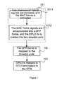
- Figure 1 is a flowchart of a method for transmitting Ethernet signals in an OTN according to an embodiment of the present invention
- Figure 2 shows how an OPU3-5v is divided into timeslots according to the embodiment illustrated in Figure 1 ;
- Figure 3 shows a structure of an apparatus for transmitting Ethernet signals in an OTN according to an embodiment of the present invention
- Figure 4 shows a structure of an apparatus for transmitting Ethernet signals in an OTN according to another embodiment of the present invention.
- Figure 5 shows a structure of a system for transmitting Ethernet signals in an OTN according to an embodiment of the present invention.
- an Ethernet signal such as 100GE signal is mapped to an adaptation protocol frame such as Generic Framing Procedure (GFP) frame, Link Access Procedure for SDH (LAPS) protocol frame, or High level Data Link Control (HDLC) protocol frame.
- GFP Generic Framing Procedure
- LAPS Link Access Procedure for SDH
- HDLC High level Data Link Control
- the VCG is divided into timeslot units adaptable to Ethernet signals. After the adaptation protocol frame is mapped to the timeslot units, the OPUk in the VCG bears the Ethernet signals carried in the adaptation protocol frame. After OPUk is mapped to OTUk, the signals are transmitted in the OTN through OTUk. Therefore, the Ethernet signals are transmitted in the OTN transparently, thus reducing the wavelength occupation drastically and improving the bandwidth utilization ratio.
- FIG. 1 is a flowchart of a method for transmitting Ethernet signals in an OTN in an embodiment of the present invention. Taking the transmission of 100GE signals in the OTN as an example, the detailed process is as follows:
- Step 101 Two channels of 100GE signals are mapped to adaptation protocol frames respectively.
- the adaptation frame may be a GFP, LAPS, or HDLC protocol; or four channels of 100GE signals are mapped to adaptation protocol frames, which will not be detailed here any further.
- the adaptation protocol is GFP and the implementation includes the following two steps:
- Step 1011 Two channels of 100GE signals undergo Physical Coding Sublayer (PCS) decoding. After the Inter-Packet Gap (IPG) information and preamble information are removed, two channels of MAC frames are extracted out.
- PCS Physical Coding Sublayer
- Step 1012 The obtained two channels of MAC frame signals are encapsulated into two channels of GFP-Framing (GFP-F) signals respectively, or the MAC frame signals may be encapsulated into GFP-Transparent (GFP-T) frame signals as required, which will not be detailed any further.
- GFP-F GFP-Framing
- GFP-T GFP-Transparent
- connection sequence check bytes may be added in the reserved overhead bytes of the two channels of GFP-F frames respectively to check correctness of multiple channels of GFP frames mapped to the OPU3-5v timeslot units.
- the VCG is divided into timeslots.
- Five OPUs with a level-3 rate (namely, OPU3) constitute a VCG, namely, OPU3-5v.
- the OPU3-5v is divided into two timeslot units TS1 and TS2, which correspond to 100GE signals respectively.
- Figure 2 shows the division of an OPU3-5v composed of five OPU3's (namely, OPU3-1, OPU3-2, OPU3-3, OPU3-4, and OPU3-5).
- the VCG (which is named "XJL") of the OPU3-5v is divided and the OPU3's are assigned into multiple timeslot units: OPU3-1 and OPU3-3 are assigned to the timeslot unit "TS1" corresponding to the first channel of 100GE signals; OPU3-2 and OPU3-4 are assigned to TS2 corresponding to the second channel of 100GE signals; and OPU3-5 adapts to the two channels of 100GE signals alternately, namely, OPU3-5 is assigned to TS1 and TS2 alternately.
- the rate of one OPU3 is about 40 Gbps
- the total rate of an OPU3-5v is 200.752595Gbps ⁇ 20 ppm
- the capacity of the payload area of TS1 and TS2 is 100.3762975 Gbps ⁇ 20 ppm, which is greater than 100GE. Therefore, the MAC frames of the 100GE signals are fully bearable, and the MAC frames can be transmitted transparently.
- the link capacity is adjusted through a Link Capacity Adjustment Scheme (LCAS)
- LCAS Link Capacity Adjustment Scheme
- division mode is not restricted. Other division modes are also applicable.
- a VCG (OPU3-6v) composed of six OPU3's is divided into three timeslot units that adapt to 100GE signals respectively so that three channels of 100GE signals can be mapped to OTUs, which will not be detailed here any further.
- the division of the VCG into timeslot units is not necessarily simultaneous to step 101, and may be performed anytime before the adaptation protocol frame is mapped to the timeslot unit as required, which will not be detailed here any further.
- Step 102 The adaptation protocol frame is mapped to the timeslot unit.
- the corresponding implementation mode is: A management frame is inserted into a GFP frame to implement management and maintenance for the GFP frame as specifically required.
- a certain number of idle frames may be inserted into the two channels of GFP frames respectively so that the rates of the two channels of GFP frames are equal to the rates of TS1 and TS2 respectively.
- the TS1 and TS2 in the OPU3-5v fully bear the MAC frames of the 100GE signals respectively.
- the quantity of the OPU3's in a VCG may be adjusted through an LCAS to control the link capacity.
- the specific implementation may be the following.
- An LCAS is configured through a Network Management System (NMS) so that the link capacity is adjusted to meet the customer requirements, for example, an OPU3-5v composed of five channel payload units.
- NMS Network Management System
- the LCAS adjusts the link capacity between 1*OPU3 and 5*OPU3 in real time, and the bandwidth for transmitting the 100GE signals is adjusted by adjusting the quantity of OPUs in the VCG.
- Step 103 The OPU3 is mapped into OTU3 and output to the OTN.
- the five OPU3s in the OPU3-5v are assigned to five channels, and encapsulated into an Optical channel Data Unit (ODU) whose rate level is 3, namely, ODU3. Afterward, the ODU3 is encapsulated to form an OTU3, modulated to the optical media, and output to the OTN.
- ODU3 Optical channel Data Unit
- the mapping between OPU3, ODU3 and OTU3 is described in the ITU-T G.709 recommendations.
- the method for transmitting Ethernet signals in the OTN in an embodiment of the present invention may further include:
- An apparatus for transmitting Ethernet signals in an OTN includes: a first adaptation protocol frame mapping module, adapted to map an Ethernet signal to an adaptation protocol frame; a first virtual concatenation module, adapted to: divide a VCG composed of multiple OPUs into timeslot units, and map the adaptation protocol frame to the timeslot units; and a first line terminal module, adapted to: map the OPU into an OTU so that the OTU bears the Ethernet signal, and output the OTU to the OTN, thus implementing transmission of an Ethernet signal in the OTN.
- an apparatus for recovering the Ethernet signal from the OTU may apply.
- This apparatus includes: a second line terminal module, adapted to demap the OTU sent by the OTN into an OPU; a second virtual concatenation module, adapted to: assemble the OPUs that derive from demapping performed by the second line terminal module into a VCG, and demap the VCG into an adaptation protocol frame; and a second adaptation protocol frame mapping module, adapted to: demap the adaptation protocol frame that derives from demapping performed by the second virtual concatenation module into an Ethernet signal, and output the Ethernet signal to the Ethernet so that the Ethernet signal is recovered from the OTU which bears the Ethernet signal.
- Figure 3 shows a structure of an apparatus for transmitting Ethernet signals in an OTN in an embodiment of the present invention.
- This apparatus includes: a first adaptation protocol frame mapping module Z11, a second adaptation protocol frame mapping module Z12, a first virtual concatenation module Z21, a second virtual concatenation module Z22, a first line terminal module Z31, and a second line terminal module Z32.
- Z11 and Z12 are encapsulated together
- Z21 and Z22 are encapsulated together
- Z31 and Z32 are encapsulated together.
- the first adaptation protocol frame mapping module Z11 is adapted to map the Ethernet signal into an adaptation protocol frame, for example, map two channels of 100GE signals into an adaptation protocol frame such as GFP frame, LAPS frame or HDLC frame.
- the first adaptation protocol frame mapping module Z11 performs PCS decoding for the Ethernet signal sent by the Ethernet, extracts the MAC frame from the decoded signal, encapsulates the MAC frame into an adaptation protocol frame, and sends the adaptation protocol frame to the first virtual concatenation module Z21.
- the first virtual concatenation module Z21 is adapted to divide a VCG composed of multiple OPUs into timeslot units, for example, divide a VCG composed of five OPUs into two timeslot units, and map the adaptation protocol frame to the timeslot units.
- the first virtual concatenation module Z21 may also be connected with a management and control module Z4. As shown in Figure 4 , the management and control module Z4 generates a capacity control command according to the manually configured capacity parameters, and sends the command to the first virtual concatenation module Z21. The first virtual concatenation module Z21 adjusts the capacity of the link connected with the first line terminal module Z31 according to the capacity control command.
- the first adaptation protocol frame mapping module Z11 may also detect the MAC frame traffic, and sends the MAC frame traffic to the management and control module Z4.
- the management and control module Z4 calculates the optimum link capacity according to the traffic data sent by the first adaptation protocol frame mapping module Z11, generates a capacity control command, and sends the command to the first virtual concatenation module Z21.
- the first virtual concatenation module Z21 adjusts the capacity of the link connected with the first line terminal module Z31 according to the capacity control command.
- the first line terminal module Z31 is adapted to: map OPU3 into OTU3 after receiving the OPU3 sent by the first virtual concatenation module Z21, and output the OTU3 to the OTN.
- the second line terminal module Z32 is adapted to receive the OTU3 from the OTN, and demap the OTU3 into OPU3;
- the second virtual concatenation module Z22 is adapted to receive the OPU3 from the second line terminal module Z32, assemble the OPU3 into a VCG, and demap the VCG into an adaptation protocol frame;
- the second adaptation protocol frame mapping module Z12 is adapted to: demap the adaptation protocol frame that derives from demapping performed by the second virtual concatenation module Z22 into a MAC frame, insert IPG information and preamble information into the MAC frame, perform PCS encoding, generate an Ethernet signal, and output the signal to the Ethernet.
- the first adaptation protocol frame mapping module Z11 and the second adaptation protocol frame mapping module Z12 may also be set on both sides of the OTN. It is the same with the first virtual concatenation module Z21 and the second virtual concatenation module Z22, and it is the same as the first line terminal module Z31 and the second line terminal module Z32.
- the first adaptation protocol frame mapping module Z11, the first virtual adaptation module Z21, and the first line terminal module Z31 are set on one side of the OTN to convert an Ethernet signal to an OTU, and send the OTU to the OTN;
- the second adaptation protocol frame mapping module Z12, the second virtual adaptation module Z22, and the second line terminal module Z32 are set on the other side of the OTN to recover the Ethernet signal from the OTU that bears the Ethernet signal, and constitute a system where transmission of Ethernet signals in the OTN may be implemented.
- the first adaptation protocol frame mapping module Z11 is adapted to map an Ethernet signal into an adaptation protocol frame;
- the first virtual concatenation module Z21 is adapted to divide a VCG composed of multiple OPUs into timeslot units, and map the adaptation protocol frame to the timeslot units;
- the first line terminal module Z31 is adapted to map the OPU into an OTU, and output the OTU to the OTN.
- the second line terminal module Z32 is adapted to demap the OTU received from the OTN to an OPU, where the OTU is output by the first line terminal module Z31 to the OTN;
- the second virtual concatenation module Z22 is adapted to assemble the OPUs that derive from demapping performed by the second line terminal module Z32 into a VCG, and demap the VCG into an adaptation protocol frame;
- the second adaptation protocol frame mapping module Z12 is adapted to demap the adaptation protocol frame that derives from demapping performed by the second virtual concatenation module Z22 into an Ethernet signal, and output the signal to the Ethernet.
- an OPU3-5v is divided into two timeslot units adaptable to the 100GE signals.
- the five OPU3's in the VCG bear the MAC frames of the two channels of 100GE signals. Therefore, the 100GE signals are transmitted in the OTN transparently, with one channel of 100GE signals occupying only 2.5 chromatic wavelengths. The wavelengths are saved massively, the bandwidth utilization ratio is improved to 99.6%, and the cost of transmitting Ethernet signals on the OTN is slashed.
- the Ethernet signals may be converted to OTUs and sent to the OTN, thus implementing transmission of Ethernet signals in the OTN.
- Ethernet signals are recovered from the OTUs that bear Ethernet signals, and sent to the Ethernet for further transmission.
- the method for transmitting Ethernet signals in an OTN under the present invention may be implemented through independent software, and such software may be stored in any computer-readable storage media.
- the software may be stored in a recording medium or a disk medium pluggable into a computer system driver; stored in a magnetic, optical or magneto-optical mode; or stored in a fixed recording medium such as hard disk drive in a computer system, or a solid-state computer memory.
- the Ethernet signals or OTU signals are input into the computer system.
- the computer system outputs and sends the OTU signals to the OTN for transmission, or outputs and sends Ethernet signals to the Ethernet for transmission.
Landscapes
- Engineering & Computer Science (AREA)
- Computer Networks & Wireless Communication (AREA)
- Signal Processing (AREA)
- Time-Division Multiplex Systems (AREA)
- Small-Scale Networks (AREA)
- Optical Communication System (AREA)
Claims (11)
- Verfahren zum Übertragen von 100G-Ethernet-Signalen in einem optischen Transportnetzwerk OTN, umfassend:Abbilden jedes von mehreren Kanälen von 100G-Ethernet-Signalen auf Anpassungsprotokollrahmen; Aufteilen einer aus X optischen Kanalnutzinformationseinheiten mit einer Rate der Ebene 3 OPU3 zusammengesetzten Virtual Concatenation Group VCG in Y an die Ethernet-Signale anpassbare Zeitschlitzeinheiten gemäß einer Rate der Ethernet-Signale; wobei Y kleiner als X ist und X, Y ganze Zahlen sind;Abbilden der Anpassungsprotokollrahmen auf die Zeitschlitzeinheiten; undAbbilden von abgebildeten OPU3 auf optische Kanalübertragungseinheiten OTU3 und Ausgeben der OTU3 an das OTN zur Übertragung.
- Verfahren nach Anspruch 1, wobei das Abbilden der Ethernet-Signale auf die Anpassungsprotokollrahmen Folgendes umfasst:Abbilden der Ethernet-Signale auf die Anpassungsprotokollrahmen durch Einkapselung des Typs Generic Framing Procedure-Transparent GFP-T oder Einkapselung des Typs Generic Framing Procedure-Framing GFP-F.
- Verfahren nach Anspruch 2, wobei
ein Leerlaufrahmen und/oder Anpassungsprotokoll-Verwaltungsrahmen in die Anpassungsprotokollrahmen eingefügt wird, nachdem die Ethernet-Signale auf die Anpassungsprotokollrahmen abgebildet wurden. - Verfahren nach Anspruch 1 oder Anspruch 2, wobei Abbilden der Ethernet-Signale auf die Anpassungsprotokollrahmen ferner Folgendes umfasst:Hinzufügen eines Verbindungssequenz-Prüfbyte zu einem reservierten Overhead-Byte der Anpassungsprotokollrahmen.
- Verfahren nach Anspruch 1-3, wobei
die 100G-Ethernet-Signale zwei Kanäle von 100GE-Signalen sind;
X gleich 5, Y gleich 2 ist; und
der Schritt des Aufteilens dann Folgendes umfasst:Vergeben von OPU3-1 und OPU3-3 an die erste Zeitschlitzeinheit, die dem ersten Kanal von 100GE-Signalen entspricht;Vergeben von OPU3-2 und OPU3-4 an die zweite Zeitschlitzeinheit, die dem zweiten Kanal von 100GE-Signalen entspricht; undabwechselndes Vergeben von OPU3-5 an den ersten Zeitschlitz und den zweiten Zeitschlitz. - Verfahren nach Anspruch 1-3, wobei
die 100GE-Ethernet-Signale zwei Kanäle von 100GE-Signalen sind;
X gleich 6, Y gleich 3 ist; und
der Schritt des Aufteilens dann Folgendes umfasst:Vergeben von OPU3-1 und OPU3-3 an die erste Zeitschlitzeinheit, die dem ersten Kanal von 100GE-Signalen entspricht;Vergeben von OPU3-2 und OPU3-4 an die zweite Zeitschlitzeinheit, die dem zweiten Kanal von 100GE-Signalen entspricht; undVergeben von OPU3-5 und OPU3-6 an den dritten Zeitschlitz. - Verfahren nach einem der Ansprüche 1-4, wobei das Verfahren, bevor die Ethernet-Rahmen auf die Anpassungsprotokollrahmen abgebildet werden, ferner Folgendes umfasst:Justieren der Menge der OPU in der VCG dynamisch durch ein Link Capacity Adjustment Scheme LCAS gemäß voreingestellten Parametern oder aktuellem Streckenverkehr.
- Verfahren nach Anspruch 1, ferner umfassend:Empfangen der OTU, die von dem OTN gesendet werden, und Entabbilden der OTU3 auf die OPU3;Assemblieren der OPU3 in die VCG und Entabbilden der VCG auf die Anpassungsprotokollrahmen; undEntabbilden der Anpassungsprotokollrahmen auf die Ethernet-Signale.
- Vorrichtung zum Übertragen von 100G-Ethernet-Signalen in einem optischen Transportnetzwerk OTN, umfassend:ein erstes Anpassungsprotokoll-Rahmenabbildungsmodul (Z11), das dafür ausgelegt ist, jeden von mehreren Kanälen von 100G-Ethernet-Signalen auf Anpassungsprotokollrahmen abzubilden;ein erstes Modul der virtuellen Verkettung (Z21), das für Folgendes ausgelegt ist:Aufteilen einer aus X optischen Kanalnutzinformationseinheiten-3 OPU3 zusammengesetzten Virtual Concatenation Group VCG in Y an die Ethernet-Signale anpassbare Zeitschlitzeinheiten gemäß einer Rate der Ethernet-Signale; und Abbilden der Anpassungsprotokollrahmen auf die Zeitschlitzeinheiten; wobei Y kleiner als X ist und X, Y ganze Zahlen sind; undein erstes Leitungsterminalmodul (Z31), das für Folgendes ausgelegt ist: Abbilden der OPU3 auf Optical Channel Transmission Units OTU3 und Ausgeben der OTU3 an das OTN.
- Vorrichtung nach Anspruch 9, wobei
die Vorrichtung ferner ein Verwaltungs- und Steuermodul (Z4) umfasst, das dafür ausgelegt ist, einen Kapazitätssteuerbefehl zu erzeugen; und
das erste Modul der virtuellen Verkettung die Kapazität einer Strecke zwischen dem ersten Modul der virtuellen Verkettung und dem ersten Leitungsterminalmodul gemäß dem Kapazitätssteuerbefehl justiert. - Vorrichtung nach Anspruch 10, wobei
das erste Anpassungsprotokollrahmen-Abbildungsmodul ferner dafür ausgelegt ist, Verkehr der Ethernet-Signale zu detektieren; und
das Verwaltungs- und Steuermodul den Kapazitätssteuerbefehl zum Justieren der Kapazität der Strecke gemäß dem durch das erste Anpassungsprotokollrahmen-Abbildungsmodul detektierten Verkehr der Ethernet-Signale erzeugt.
Applications Claiming Priority (2)
| Application Number | Priority Date | Filing Date | Title |
|---|---|---|---|
| CN2007100637838A CN101242232B (zh) | 2007-02-09 | 2007-02-09 | 实现以太网信号在光传送网中传输的方法、装置及系统 |
| PCT/CN2008/000189 WO2008098466A1 (en) | 2007-02-09 | 2008-01-25 | A method, apparatus and system for realizing transmitting ethernet signal in the optical transport network |
Publications (3)
| Publication Number | Publication Date |
|---|---|
| EP2071753A1 EP2071753A1 (de) | 2009-06-17 |
| EP2071753A4 EP2071753A4 (de) | 2009-12-16 |
| EP2071753B1 true EP2071753B1 (de) | 2012-12-12 |
Family
ID=39689641
Family Applications (1)
| Application Number | Title | Priority Date | Filing Date |
|---|---|---|---|
| EP08700734A Active EP2071753B1 (de) | 2007-02-09 | 2008-01-25 | Verfahren, vorrichtung und system zur verwirklichung von ethernet-übertragung im optischen transport-netzwerk |
Country Status (6)
| Country | Link |
|---|---|
| US (1) | US8180224B2 (de) |
| EP (1) | EP2071753B1 (de) |
| CN (1) | CN101242232B (de) |
| DK (1) | DK2071753T3 (de) |
| ES (1) | ES2398401T3 (de) |
| WO (1) | WO2008098466A1 (de) |
Families Citing this family (15)
| Publication number | Priority date | Publication date | Assignee | Title |
|---|---|---|---|---|
| CN101841749B (zh) * | 2009-03-18 | 2013-10-02 | 华为技术有限公司 | 数据传输方法、通信装置及通信系统 |
| CN101841740A (zh) * | 2009-03-20 | 2010-09-22 | 华为技术有限公司 | 在光传送网中发送、接收高速以太网数据流的方法和装置 |
| ES2843024T3 (es) * | 2009-07-27 | 2021-07-15 | Huawei Tech Co Ltd | Método y aparato de tratamiento de transmisión de señal y estación de base distribuida |
| CN101656588A (zh) * | 2009-09-21 | 2010-02-24 | 中兴通讯股份有限公司 | 一种传输数据的方法及系统 |
| WO2011075901A1 (zh) * | 2009-12-24 | 2011-06-30 | 华为技术有限公司 | 通用映射规程gmp映射方法、解映射方法及装置 |
| CN102196321A (zh) * | 2010-03-05 | 2011-09-21 | 华为技术有限公司 | 100ge数据在光传送网中的传送方法和数据发送装置 |
| CN103036847B (zh) * | 2011-09-29 | 2015-11-25 | 厦门福信光电集成有限公司 | 一种自动识别hdlc/gfp型用户端协议转换器的汇聚型协议转换器及其收发方法 |
| US8934479B2 (en) * | 2011-10-28 | 2015-01-13 | Infinera Corporation | Super optical channel transport unit signal supported by multiple wavelengths |
| CN102783178B (zh) * | 2012-05-15 | 2015-07-29 | 华为技术有限公司 | 一种光传送网的数据处理方法、相关设备及系统 |
| CN103546226B (zh) * | 2012-07-16 | 2016-12-21 | 中兴通讯股份有限公司 | Vcg差分时延的处理方法及装置 |
| CN106301661B (zh) | 2012-07-30 | 2018-10-19 | 华为技术有限公司 | 光传送网中传送、接收客户信号的方法和装置 |
| US9825696B2 (en) * | 2016-01-13 | 2017-11-21 | Ciena Corporation | Ethernet link state signaling for packet flows mapped into optical transport network with generic framing procedure |
| CN112511916A (zh) * | 2020-02-28 | 2021-03-16 | 中兴通讯股份有限公司 | 光传送网中业务处理方法、处理装置和电子设备 |
| CN114500650A (zh) * | 2022-01-25 | 2022-05-13 | 瀚云科技有限公司 | 一种交通数据处理方法、装置、服务器及系统 |
| CN115766462A (zh) * | 2022-12-19 | 2023-03-07 | 安徽皖通邮电股份有限公司 | 基于光传送网链路的带宽调整方法及存储介质 |
Family Cites Families (6)
| Publication number | Priority date | Publication date | Assignee | Title |
|---|---|---|---|---|
| JP4224400B2 (ja) * | 2001-08-24 | 2009-02-12 | ルーミー, エス. ゴンダ, | Sdh/sonetフレームをイーサネットフレームに変換するための方法及び装置 |
| CN1299448C (zh) * | 2002-07-24 | 2007-02-07 | 中兴通讯股份有限公司 | 一种以太网无源光纤网络的实现方法 |
| CN100349390C (zh) * | 2004-08-11 | 2007-11-14 | 华为技术有限公司 | 光传送网中传输低速率业务信号的方法及其装置 |
| CN1747606B (zh) * | 2004-09-09 | 2011-02-09 | 华为技术有限公司 | 业务数据传输方法及装置 |
| CN100373847C (zh) * | 2004-12-14 | 2008-03-05 | 华为技术有限公司 | 在光传送网中传输低速率业务信号的方法 |
| CN100401715C (zh) * | 2005-12-31 | 2008-07-09 | 华为技术有限公司 | 局域网信号在光传送网中传输的实现方法和装置 |
-
2007
- 2007-02-09 CN CN2007100637838A patent/CN101242232B/zh active Active
-
2008
- 2008-01-25 WO PCT/CN2008/000189 patent/WO2008098466A1/zh not_active Ceased
- 2008-01-25 EP EP08700734A patent/EP2071753B1/de active Active
- 2008-01-25 DK DK08700734.0T patent/DK2071753T3/da active
- 2008-01-25 ES ES08700734T patent/ES2398401T3/es active Active
-
2009
- 2009-04-27 US US12/430,471 patent/US8180224B2/en active Active
Also Published As
| Publication number | Publication date |
|---|---|
| US8180224B2 (en) | 2012-05-15 |
| EP2071753A4 (de) | 2009-12-16 |
| WO2008098466A1 (en) | 2008-08-21 |
| EP2071753A1 (de) | 2009-06-17 |
| DK2071753T3 (da) | 2013-02-11 |
| CN101242232B (zh) | 2013-04-17 |
| US20090208208A1 (en) | 2009-08-20 |
| ES2398401T3 (es) | 2013-03-15 |
| CN101242232A (zh) | 2008-08-13 |
Similar Documents
| Publication | Publication Date | Title |
|---|---|---|
| EP2071753B1 (de) | Verfahren, vorrichtung und system zur verwirklichung von ethernet-übertragung im optischen transport-netzwerk | |
| US8693480B2 (en) | Method, apparatus and system for transmitting and receiving client signals | |
| US9497064B2 (en) | Method and apparatus for transporting ultra-high-speed Ethernet service | |
| EP1826926B1 (de) | Implementierungsverfahren für ein in einem optischen transportnetz gesendetes kurzratenverkehrssignal | |
| EP3462647B1 (de) | Verfahren zum transportieren von client-signalen in einem optischen transportnetzwerk und transportvorrichtung | |
| US8948205B2 (en) | Method and apparatus for mapping and de-mapping in an optical transport network | |
| EP2365652B1 (de) | Verfahren und Vorrichtungen zur Übertragung von Client-Signalen in ein optisches Transportnetzwerk | |
| JP4878629B2 (ja) | 多重伝送システムおよび多重伝送方法 | |
| US7944928B2 (en) | Method and apparatus for transporting local area network signals in optical transport network | |
| EP1737147A1 (de) | Übertragungsverfahren für verkehrssignale mit geringer geschwindigkeitsrate in einem optischen übertragungsnetzwerk und vorrichtung | |
| EP2852177B1 (de) | Verfahren und vorrichtung zur zuweisung einer bandbreitenressource mit optischem frequenzspektrum | |
| EP2854417A1 (de) | Verfahren und vorrichtung zum senden und empfangen eines client-signals | |
| WO2008122218A1 (en) | A method for multiplexing and de-multiplexing the low bit rate service | |
| JP6779285B2 (ja) | 信号を送受信する方法、装置、およびシステム | |
| CN107968699A (zh) | 一种OTN网络中2Mbit/s低速信号的传输方法 | |
| WO2016074484A1 (zh) | 分组业务信号发送方法、装置及接收方法、装置 |
Legal Events
| Date | Code | Title | Description |
|---|---|---|---|
| PUAI | Public reference made under article 153(3) epc to a published international application that has entered the european phase |
Free format text: ORIGINAL CODE: 0009012 |
|
| 17P | Request for examination filed |
Effective date: 20090428 |
|
| AK | Designated contracting states |
Kind code of ref document: A1 Designated state(s): AT BE BG CH CY CZ DE DK EE ES FI FR GB GR HR HU IE IS IT LI LT LU LV MC MT NL NO PL PT RO SE SI SK TR |
|
| A4 | Supplementary search report drawn up and despatched |
Effective date: 20091112 |
|
| REG | Reference to a national code |
Ref country code: DE Ref legal event code: R079 Ref document number: 602008020770 Country of ref document: DE Free format text: PREVIOUS MAIN CLASS: H04J0014000000 Ipc: H04J0014020000 |
|
| RIC1 | Information provided on ipc code assigned before grant |
Ipc: H04J 3/16 20060101ALI20120412BHEP Ipc: H04J 14/02 20060101AFI20120412BHEP |
|
| GRAP | Despatch of communication of intention to grant a patent |
Free format text: ORIGINAL CODE: EPIDOSNIGR1 |
|
| DAX | Request for extension of the european patent (deleted) | ||
| GRAS | Grant fee paid |
Free format text: ORIGINAL CODE: EPIDOSNIGR3 |
|
| GRAA | (expected) grant |
Free format text: ORIGINAL CODE: 0009210 |
|
| AK | Designated contracting states |
Kind code of ref document: B1 Designated state(s): AT BE BG CH CY CZ DE DK EE ES FI FR GB GR HR HU IE IS IT LI LT LU LV MC MT NL NO PL PT RO SE SI SK TR |
|
| REG | Reference to a national code |
Ref country code: GB Ref legal event code: FG4D |
|
| REG | Reference to a national code |
Ref country code: CH Ref legal event code: EP |
|
| REG | Reference to a national code |
Ref country code: AT Ref legal event code: REF Ref document number: 588764 Country of ref document: AT Kind code of ref document: T Effective date: 20121215 |
|
| REG | Reference to a national code |
Ref country code: IE Ref legal event code: FG4D |
|
| REG | Reference to a national code |
Ref country code: DE Ref legal event code: R096 Ref document number: 602008020770 Country of ref document: DE Effective date: 20130131 |
|
| REG | Reference to a national code |
Ref country code: DK Ref legal event code: T3 |
|
| REG | Reference to a national code |
Ref country code: NL Ref legal event code: T3 |
|
| REG | Reference to a national code |
Ref country code: ES Ref legal event code: FG2A Ref document number: 2398401 Country of ref document: ES Kind code of ref document: T3 Effective date: 20130315 |
|
| PG25 | Lapsed in a contracting state [announced via postgrant information from national office to epo] |
Ref country code: LT Free format text: LAPSE BECAUSE OF FAILURE TO SUBMIT A TRANSLATION OF THE DESCRIPTION OR TO PAY THE FEE WITHIN THE PRESCRIBED TIME-LIMIT Effective date: 20121212 Ref country code: SE Free format text: LAPSE BECAUSE OF FAILURE TO SUBMIT A TRANSLATION OF THE DESCRIPTION OR TO PAY THE FEE WITHIN THE PRESCRIBED TIME-LIMIT Effective date: 20121212 Ref country code: NO Free format text: LAPSE BECAUSE OF FAILURE TO SUBMIT A TRANSLATION OF THE DESCRIPTION OR TO PAY THE FEE WITHIN THE PRESCRIBED TIME-LIMIT Effective date: 20130312 Ref country code: FI Free format text: LAPSE BECAUSE OF FAILURE TO SUBMIT A TRANSLATION OF THE DESCRIPTION OR TO PAY THE FEE WITHIN THE PRESCRIBED TIME-LIMIT Effective date: 20121212 |
|
| REG | Reference to a national code |
Ref country code: AT Ref legal event code: MK05 Ref document number: 588764 Country of ref document: AT Kind code of ref document: T Effective date: 20121212 |
|
| REG | Reference to a national code |
Ref country code: LT Ref legal event code: MG4D |
|
| PG25 | Lapsed in a contracting state [announced via postgrant information from national office to epo] |
Ref country code: LV Free format text: LAPSE BECAUSE OF FAILURE TO SUBMIT A TRANSLATION OF THE DESCRIPTION OR TO PAY THE FEE WITHIN THE PRESCRIBED TIME-LIMIT Effective date: 20121212 Ref country code: SI Free format text: LAPSE BECAUSE OF FAILURE TO SUBMIT A TRANSLATION OF THE DESCRIPTION OR TO PAY THE FEE WITHIN THE PRESCRIBED TIME-LIMIT Effective date: 20121212 Ref country code: GR Free format text: LAPSE BECAUSE OF FAILURE TO SUBMIT A TRANSLATION OF THE DESCRIPTION OR TO PAY THE FEE WITHIN THE PRESCRIBED TIME-LIMIT Effective date: 20130313 |
|
| PG25 | Lapsed in a contracting state [announced via postgrant information from national office to epo] |
Ref country code: BG Free format text: LAPSE BECAUSE OF FAILURE TO SUBMIT A TRANSLATION OF THE DESCRIPTION OR TO PAY THE FEE WITHIN THE PRESCRIBED TIME-LIMIT Effective date: 20130312 Ref country code: SK Free format text: LAPSE BECAUSE OF FAILURE TO SUBMIT A TRANSLATION OF THE DESCRIPTION OR TO PAY THE FEE WITHIN THE PRESCRIBED TIME-LIMIT Effective date: 20121212 Ref country code: EE Free format text: LAPSE BECAUSE OF FAILURE TO SUBMIT A TRANSLATION OF THE DESCRIPTION OR TO PAY THE FEE WITHIN THE PRESCRIBED TIME-LIMIT Effective date: 20121212 Ref country code: CZ Free format text: LAPSE BECAUSE OF FAILURE TO SUBMIT A TRANSLATION OF THE DESCRIPTION OR TO PAY THE FEE WITHIN THE PRESCRIBED TIME-LIMIT Effective date: 20121212 Ref country code: IS Free format text: LAPSE BECAUSE OF FAILURE TO SUBMIT A TRANSLATION OF THE DESCRIPTION OR TO PAY THE FEE WITHIN THE PRESCRIBED TIME-LIMIT Effective date: 20130412 Ref country code: AT Free format text: LAPSE BECAUSE OF FAILURE TO SUBMIT A TRANSLATION OF THE DESCRIPTION OR TO PAY THE FEE WITHIN THE PRESCRIBED TIME-LIMIT Effective date: 20121212 |
|
| PG25 | Lapsed in a contracting state [announced via postgrant information from national office to epo] |
Ref country code: PT Free format text: LAPSE BECAUSE OF FAILURE TO SUBMIT A TRANSLATION OF THE DESCRIPTION OR TO PAY THE FEE WITHIN THE PRESCRIBED TIME-LIMIT Effective date: 20130412 Ref country code: PL Free format text: LAPSE BECAUSE OF FAILURE TO SUBMIT A TRANSLATION OF THE DESCRIPTION OR TO PAY THE FEE WITHIN THE PRESCRIBED TIME-LIMIT Effective date: 20121212 Ref country code: MC Free format text: LAPSE BECAUSE OF NON-PAYMENT OF DUE FEES Effective date: 20130131 Ref country code: RO Free format text: LAPSE BECAUSE OF FAILURE TO SUBMIT A TRANSLATION OF THE DESCRIPTION OR TO PAY THE FEE WITHIN THE PRESCRIBED TIME-LIMIT Effective date: 20121212 |
|
| REG | Reference to a national code |
Ref country code: CH Ref legal event code: PL |
|
| PLBE | No opposition filed within time limit |
Free format text: ORIGINAL CODE: 0009261 |
|
| STAA | Information on the status of an ep patent application or granted ep patent |
Free format text: STATUS: NO OPPOSITION FILED WITHIN TIME LIMIT |
|
| REG | Reference to a national code |
Ref country code: IE Ref legal event code: MM4A |
|
| PG25 | Lapsed in a contracting state [announced via postgrant information from national office to epo] |
Ref country code: CH Free format text: LAPSE BECAUSE OF NON-PAYMENT OF DUE FEES Effective date: 20130131 Ref country code: LI Free format text: LAPSE BECAUSE OF NON-PAYMENT OF DUE FEES Effective date: 20130131 |
|
| 26N | No opposition filed |
Effective date: 20130913 |
|
| PG25 | Lapsed in a contracting state [announced via postgrant information from national office to epo] |
Ref country code: HR Free format text: LAPSE BECAUSE OF FAILURE TO SUBMIT A TRANSLATION OF THE DESCRIPTION OR TO PAY THE FEE WITHIN THE PRESCRIBED TIME-LIMIT Effective date: 20121212 Ref country code: CY Free format text: LAPSE BECAUSE OF FAILURE TO SUBMIT A TRANSLATION OF THE DESCRIPTION OR TO PAY THE FEE WITHIN THE PRESCRIBED TIME-LIMIT Effective date: 20121212 |
|
| REG | Reference to a national code |
Ref country code: DE Ref legal event code: R097 Ref document number: 602008020770 Country of ref document: DE Effective date: 20130913 |
|
| PG25 | Lapsed in a contracting state [announced via postgrant information from national office to epo] |
Ref country code: IE Free format text: LAPSE BECAUSE OF NON-PAYMENT OF DUE FEES Effective date: 20130125 |
|
| PG25 | Lapsed in a contracting state [announced via postgrant information from national office to epo] |
Ref country code: MT Free format text: LAPSE BECAUSE OF FAILURE TO SUBMIT A TRANSLATION OF THE DESCRIPTION OR TO PAY THE FEE WITHIN THE PRESCRIBED TIME-LIMIT Effective date: 20121212 |
|
| PG25 | Lapsed in a contracting state [announced via postgrant information from national office to epo] |
Ref country code: TR Free format text: LAPSE BECAUSE OF FAILURE TO SUBMIT A TRANSLATION OF THE DESCRIPTION OR TO PAY THE FEE WITHIN THE PRESCRIBED TIME-LIMIT Effective date: 20121212 |
|
| PG25 | Lapsed in a contracting state [announced via postgrant information from national office to epo] |
Ref country code: HU Free format text: LAPSE BECAUSE OF FAILURE TO SUBMIT A TRANSLATION OF THE DESCRIPTION OR TO PAY THE FEE WITHIN THE PRESCRIBED TIME-LIMIT; INVALID AB INITIO Effective date: 20080125 Ref country code: LU Free format text: LAPSE BECAUSE OF NON-PAYMENT OF DUE FEES Effective date: 20130125 |
|
| REG | Reference to a national code |
Ref country code: FR Ref legal event code: PLFP Year of fee payment: 9 |
|
| REG | Reference to a national code |
Ref country code: FR Ref legal event code: PLFP Year of fee payment: 10 |
|
| REG | Reference to a national code |
Ref country code: FR Ref legal event code: PLFP Year of fee payment: 11 |
|
| PGFP | Annual fee paid to national office [announced via postgrant information from national office to epo] |
Ref country code: DK Payment date: 20250113 Year of fee payment: 18 |
|
| PGFP | Annual fee paid to national office [announced via postgrant information from national office to epo] |
Ref country code: ES Payment date: 20250206 Year of fee payment: 18 |
|
| PGFP | Annual fee paid to national office [announced via postgrant information from national office to epo] |
Ref country code: GB Payment date: 20251204 Year of fee payment: 19 |
|
| PGFP | Annual fee paid to national office [announced via postgrant information from national office to epo] |
Ref country code: NL Payment date: 20251215 Year of fee payment: 19 Ref country code: FR Payment date: 20251208 Year of fee payment: 19 |
|
| PGFP | Annual fee paid to national office [announced via postgrant information from national office to epo] |
Ref country code: DE Payment date: 20251203 Year of fee payment: 19 |
|
| PGFP | Annual fee paid to national office [announced via postgrant information from national office to epo] |
Ref country code: IT Payment date: 20251219 Year of fee payment: 19 Ref country code: BE Payment date: 20260106 Year of fee payment: 19 |