EP2072981A2 - Temperature sensor and method for measuring temperature - Google Patents
Temperature sensor and method for measuring temperature Download PDFInfo
- Publication number
- EP2072981A2 EP2072981A2 EP08020278A EP08020278A EP2072981A2 EP 2072981 A2 EP2072981 A2 EP 2072981A2 EP 08020278 A EP08020278 A EP 08020278A EP 08020278 A EP08020278 A EP 08020278A EP 2072981 A2 EP2072981 A2 EP 2072981A2
- Authority
- EP
- European Patent Office
- Prior art keywords
- gas
- temperature
- temperature sensor
- housing
- probe
- Prior art date
- Legal status (The legal status is an assumption and is not a legal conclusion. Google has not performed a legal analysis and makes no representation as to the accuracy of the status listed.)
- Granted
Links
Images




Classifications
-
- G—PHYSICS
- G01—MEASURING; TESTING
- G01K—MEASURING TEMPERATURE; MEASURING QUANTITY OF HEAT; THERMALLY-SENSITIVE ELEMENTS NOT OTHERWISE PROVIDED FOR
- G01K1/00—Details of thermometers not specially adapted for particular types of thermometer
-
- G—PHYSICS
- G01—MEASURING; TESTING
- G01K—MEASURING TEMPERATURE; MEASURING QUANTITY OF HEAT; THERMALLY-SENSITIVE ELEMENTS NOT OTHERWISE PROVIDED FOR
- G01K13/00—Thermometers specially adapted for specific purposes
- G01K13/02—Thermometers specially adapted for specific purposes for measuring temperature of moving fluids or granular materials capable of flow
-
- G—PHYSICS
- G01—MEASURING; TESTING
- G01K—MEASURING TEMPERATURE; MEASURING QUANTITY OF HEAT; THERMALLY-SENSITIVE ELEMENTS NOT OTHERWISE PROVIDED FOR
- G01K1/00—Details of thermometers not specially adapted for particular types of thermometer
- G01K1/16—Special arrangements for conducting heat from the object to the sensitive element
-
- G—PHYSICS
- G01—MEASURING; TESTING
- G01K—MEASURING TEMPERATURE; MEASURING QUANTITY OF HEAT; THERMALLY-SENSITIVE ELEMENTS NOT OTHERWISE PROVIDED FOR
- G01K13/00—Thermometers specially adapted for specific purposes
- G01K13/02—Thermometers specially adapted for specific purposes for measuring temperature of moving fluids or granular materials capable of flow
- G01K13/028—Thermometers specially adapted for specific purposes for measuring temperature of moving fluids or granular materials capable of flow for use in total air temperature [TAT] probes
Definitions
- the present invention relates to a system and method for measuring the total temperature of a gas.
- the invention is applicable to total air temperature sensing on aircraft.
- Total air temperature is a measure of air temperature that is used for air flows. TAT is the static air temperature plus the adiabatic temperature rise of the air produced by the complete conversion of the kinetic energy of the air into thermal energy.
- the free stream Mach number M is a measure of the speed of the air flow past the sensor.
- the measured temperature sometimes called the recovered temperature, is different from the total temperature because of incomplete conversion of the gas motion energy into the thermal energy.
- T R T S ⁇ 1 + r ⁇ ⁇ - 1 2 ⁇ M 2
- the recovery factor depends on the effectiveness of the sensor in capturing the adiabatic temperature rise and on the ratio between the internal and external air velocities.
- the recovery factor also depends on the construction of the probe and varies with Mach number.
- Total air temperature measurement is critical to many aircraft systems.
- TAT sensors mounted on the aircraft body provide information about the air temperature that can be used to calculate true air speed.
- TAT sensors mounted at the inlet to gas turbine engines are used to provide accurate engine power settings and to select engine pressure ratios prior to take off.
- TAT measurements are also required for stall control, with inlet guide vane scheduling and for calculation of engine parameters such as corrected speed, fuel flow and fuel consumption.
- Prior TAT sensors comprise a temperature sensing element 10 mounted inside a housing 11 through which air flows, as illustrated in Figure 1 .
- the arrows in Figure 1 indicate the direction of air flow.
- the housing is mounted on a strut 12 so that the sensor air inlet is positioned away from the aircraft body and the associated boundary layer of air.
- the sensors work by slowing down the flow of air through the housing so that the kinetic energy of the air is converted into an adiabatic temperature rise.
- the airflow is divided into a through channel 13 and a deflected channel 14.
- the sensing element 10 is located in the deflected path.
- the air channels 13 and 14 are arranged in such as way that the air speed past the sensor is very much reduced. Dividing the airflow in this way also reduces the amount of water droplets and debris that impinge on the sensing element 10.
- the boundary layer formed inside the sensor housing is the boundary layer formed inside the sensor housing.
- the temperature of the walls of the housing surrounding the sensor is lower than the air temperature.
- the air close to the walls is therefore cooler that the air in the centre of the housing.
- the air close to the walls also moves more slowly than the air passing through the centre of the housing and so forms a boundary layer of cool air.
- the boundary layer thickness can build up to the extent that it will affect the measured temperature.
- a further problem associated with prior total air temperature sensors is the build up of ice on the sensor housing.
- the solution to the problem of build up of ice on the sensor housing has been to include heater elements within the housing itself.
- the de-icing heater elements affect the accuracy of the temperature measurement, as the generated heat is detected by the temperature sensor. This effect is more prominent at low speeds and can result in an error of up to 8°C.
- the heating elements can actually cause the boundary layer of air close to the interior surfaces of the housing to have a higher temperature than the main airflow and at low speed the thickness of the boundary layer can be enough to contact the sensing element.
- the present invention provides a temperature sensor and a method of sensing temperature as defined in the appended claims, to which reference should now be made.
- the present invention provides a sensor that is simple to manufacture, is robust, provides for a low recovery correction and does not suffer from significant boundary layer problems.
- the present invention also provides apparatus and methods for de-icing a temperature sensor that do not significantly affect temperature measurements taken by the temperature sensor and that use a low power. Preferred features of the invention are defined in the dependent claims.
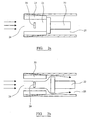
- FIGs 2a and 2b are schematic illustrations of the essential elements of a TAT sensor in accordance with the present invention.
- a temperature sensing element 20 is located in a measurement chamber 21.
- the chamber comprises side walls 23, an air inlet 24 and an air outlet 25.
- the air outlet 25 can be sealed by a valve 22.
- the valve In Figure 2a , the valve is in a closed position, sealing the outlet 25.
- the valve In Figure 2b , the valve is in an open position allowing the air to flow through the measurement chamber.
- the temperature sensor is a resistance temperature device (RTD), such as a platinum resistance thermometer (PRT) of either a wire wound or sintered film type, a tungsten resistor or a rhodium-iron RTD.
- RTD resistance temperature device
- PRT platinum resistance thermometer
- a thermistor such as a diamond thermistor, a thermocouple or optical temperature sensor may be used.
- the valve in Figure 2 is illustrated schematically and may be any suitable type of valve. It is preferably a micro-electrical mechanical system (MEMS) valve. Robust and reliable MEMS valves that can operate at high frequency (in the order of 1 KHz) are now available and are ideally suited to the present invention.
- MEMS valve can be fabricated specifically for a TAT sensor in accordance with the invention, having the desired performance characteristics. Alternatively a solenoid valve or any other suitable type of valve may be used.
- the chamber sidewalls 23 can be made of any suitable material. In MEMS devices, silicon is a preferred material.
- the measurement chamber shown in Figure 2 has a circular cross-section, with a diameter of approximately 3-5mm. However, other cross-sectional shapes and dimensions are possible.
- the valve is then opened again in step 505 to allow air to flow through the chamber as shown in Figure 2b .
- the valve remains open for a short period, again of the order of 10 milliseconds, shown as step 506, before the process is repeated and another temperature measurement taken.
- a practically continuous TAT measurement is obtained in this way.
- Typical sampling time in an aircraft engine control unit is about 20ms and this is a reasonable temperature sampling rate. For a minimum airflow of 10m/s, the air in the measurement chamber will be replaced in a few milliseconds.
- This mode of operation provides almost complete recovery of the kinetic energy of the airflow, resulting in a low recovery correction factor.
- the speed of operation of the valve also prevents the build up of a boundary layer within the measurement chamber. Air is stopped as a result of the valve being closed but is then flushed through the measurement chamber after the valve is opened. The temperature measurement is taken very shortly after the valve is closed preventing any significant thermal transfer from the sidewalls.
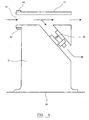
- FIG. 3 is an illustration of a TAT sensor in accordance with the present invention.
- the sensing element and measurement chamber are mounted within a housing similar to that used for prior TAT sensors.
- the sensor is mounted to the aircraft body 30 on a vane 31. Air flows through inlet 32. The air flow is then split between a straight through path exiting through outlet 33 and a deflected path exiting through outlet 34, via the measurement chamber 21. The deflection of the air before it enters the measurement chamber passes the sensing element reduces the amount of solid particles and water droplets that enter the measurement chamber.
- Boundary layer control is also less critical. As a result, the air channels can be made to a simpler and cheaper design.
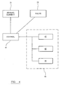
- FIG. 4 is a schematic diagram showing the electronic control elements associated with a TAT sensor in accordance with the present invention.
- Both the temperature sensing element 20 and the valve 22 are connected to an electronic controller 41.
- the controller 41 synchronises the operation of the sensing element of the valve so that temperature measurements are taken at a predetermined time following closure of the valve.
- the controller 41 also controls the frequency of operation of the valve 22. The frequency of operation of the valve may be adjusted according to particular environmental conditions and engine speed.
- the results of the temperature measurements taken by the sensing element are passed from the controller 41 into elements of the aircraft control system 40.
- the total air temperature measurements are passed to the Air dData Computer 42, the Full Authority Digital Engine Control (FADEC) 43, and to the Cockpit display 44.
- FADEC Full Authority Digital Engine Control
- MEMS pressure measurement devices may be incorporated into the chamber walls or into the valve.
- FIG. 6 illustrates a second aspect of the present invention.
- Figure 6 shows a TAT probe mounted to an aircraft body 30.
- the TAT probe may be of the type shown in Figure 1 or of a type in accordance with the first aspect of the invention as shown in Figure 3 .
- Mounted to the sensor housing 11 at the air inlet 61 are piezo-electric transducers 60 that are operable to produce ultrasonic vibrations in the housing 11.
- the transducers are driven (by electronic control means not shown) at a frequency chosen to optimally prevent deposition of any ice crystals approaching the inlet 61.
- the maximum interaction between ultrasonic waves and small particles occurs when the wavelength of waves is close to the size of particles.
- the transducers can be mounted to the housing to produce different types of waves in the housing, e.g. shear, longitudinal, transverse. These waves may be generated in combination or separately and at the same or different frequencies.
- the transducers require low power in comparison to the heater elements of the prior art. Furthermore, the transducers may be quickly switched on when icing conditions are detected and turned off otherwise, saving power.
- FIG. 6 shows ultrasonic transducers used with a TAT probe, but transducers may be used in any type of gas probe when ice build up is an issue. It is also possible to use transducers in conjunction with other de-icing techniques, such as heating elements.
- FIG. 7 illustrates a third aspect of the invention, which is another apparatus and method of preventing ice build up at the inlet to a TAT probe.
- the TAT probe shown in Figure 7 may be of the type in accordance with the first aspect of the invention as shown in Figure 3 or may be a TAT probe in accordance with the prior art, as shown in Figure 1 .
- the system shown in Figure 7 may also be applied to other types of gas probes and with other de-icing techniques.
- the system in Figure 7 shows a microwave source 70 mounted to the aircraft body 30 including microwave focussing element 71 for focussing the emitted microwave radiation onto the inlet 72 of the TAT probe or just upstream of the inlet.
- the microwave radiation is of a frequency (2.45GHz) that is strongly absorbed by water (and ice) but is not strongly absorbed by air or by the material of the housing.
- the microwave radiation will be absorbed by any ice crystals and will melt the ice crystals prior to entry into the probe without significantly heating the surrounding air.
- the microwave source 70 should be mounted close to the inlet (e.g. 3-4cm away) so that the microwaves can reach ice deposited on the inside of the housing on the lower lip.
- a significant advantage of using a microwave source is that ice build up is prevented without significantly affecting the temperature of the air entering the probe or the temperature of the housing, and so the accuracy of the temperature measurement is not compromised.
- Any suitable microwave source may be used in the system shown in Figure 7 .
- Solid-state microwave sources such as IMPATT diodes, are now widely available which are low power when compared to the heating elements of the prior art and are robust. These solid state microwave sources can be simply mounted to an aircraft body and can be quickly switched on when icing conditions are detected and switched off otherwise. The focussing elements ensure that the power required is kept to a minimum and that the microwaves do not interfere with any electronic systems on the aircraft.
Landscapes
- Physics & Mathematics (AREA)
- General Physics & Mathematics (AREA)
- Measuring Temperature Or Quantity Of Heat (AREA)
Abstract
Description
- The present invention relates to a system and method for measuring the total temperature of a gas. In particular, the invention is applicable to total air temperature sensing on aircraft.
- Total air temperature (TAT) is a measure of air temperature that is used for air flows. TAT is the static air temperature plus the adiabatic temperature rise of the air produced by the complete conversion of the kinetic energy of the air into thermal energy.
- Total Air Temperature can be expressed by the following equation:

where
Ts is the Static Air Temperature
M is the free stream Mach number
γ is the ratio of gas specific heats (1.4 at 0 deg. C) - The free stream Mach number M is a measure of the speed of the air flow past the sensor.
- However the measured temperature, sometimes called the recovered temperature, is different from the total temperature because of incomplete conversion of the gas motion energy into the thermal energy.
- Therefore the recovered temperature is given by:

where r is the recovery factor and is defined as:
- The recovery factor depends on the effectiveness of the sensor in capturing the adiabatic temperature rise and on the ratio between the internal and external air velocities. The recovery factor also depends on the construction of the probe and varies with Mach number.
- The recovered temperature TR can be expressed more conveniently by:

where
and is called the recovery correction. - Total air temperature measurement is critical to many aircraft systems.
TAT sensors mounted on the aircraft body provide information about the air temperature that can be used to calculate true air speed. TAT sensors mounted at the inlet to gas turbine engines are used to provide accurate engine power settings and to select engine pressure ratios prior to take off.
TAT measurements are also required for stall control, with inlet guide vane scheduling and for calculation of engine parameters such as corrected speed, fuel flow and fuel consumption. -
- Prior TAT sensors comprise a
temperature sensing element 10 mounted inside ahousing 11 through which air flows, as illustrated inFigure 1 . The arrows inFigure 1 indicate the direction of air flow. The housing is mounted on astrut 12 so that the sensor air inlet is positioned away from the aircraft body and the associated boundary layer of air. The sensors work by slowing down the flow of air through the housing so that the kinetic energy of the air is converted into an adiabatic temperature rise. The airflow is divided into a throughchannel 13 and adeflected channel 14. Thesensing element 10 is located in the deflected path. Theair channels sensing element 10. - There are a number of technical problems with this basic solution that have led to very complex mechanical and electrical configurations for the sensors.
- One parameter that affects the accuracy of TAT measurements is the boundary layer formed inside the sensor housing. Typically, during flight the temperature of the walls of the housing surrounding the sensor is lower than the air temperature. The air close to the walls is therefore cooler that the air in the centre of the housing. The air close to the walls also moves more slowly than the air passing through the centre of the housing and so forms a boundary layer of cool air. At low air speeds, the boundary layer thickness can build up to the extent that it will affect the measured temperature.
- In order to control the thickness of the boundary layer, prior designs have included a complex array of
apertures 15 within the housing, as shown inFigure 1 , designed to bleed off air from the boundary layer and thus control its thickness. The size and position of these holes has been empirically determined so as to reduce the effect of the boundary layer without affecting the main flow of air through the sensor. The need for accurate fabrication of the sensor housing including these holes is a major factor in the high cost of the probe. - Another problem with prior total air temperature sensors is that they are not able to completely convert the kinetic energy of the gas into an adiabatic temperature rise. The recovery correction typically varies with Mach number from 0 to about 0.6%.
- A further problem associated with prior total air temperature sensors is the build up of ice on the sensor housing. The solution to the problem of build up of ice on the sensor housing has been to include heater elements within the housing itself. However, the de-icing heater elements affect the accuracy of the temperature measurement, as the generated heat is detected by the temperature sensor. This effect is more prominent at low speeds and can result in an error of up to 8°C. The heating elements can actually cause the boundary layer of air close to the interior surfaces of the housing to have a higher temperature than the main airflow and at low speed the thickness of the boundary layer can be enough to contact the sensing element.
- The present invention provides a temperature sensor and a method of sensing temperature as defined in the appended claims, to which reference should now be made. The present invention provides a sensor that is simple to manufacture, is robust, provides for a low recovery correction and does not suffer from significant boundary layer problems. The present invention also provides apparatus and methods for de-icing a temperature sensor that do not significantly affect temperature measurements taken by the temperature sensor and that use a low power. Preferred features of the invention are defined in the dependent claims.
- Embodiments of the invention will now be described in detail, with reference to the accompanying drawings, in which:
-
Figure 1 illustrates a total air temperature probe in accordance with the prior art; -
Figure 2a is a schematic illustration of an air temperature probe in accordance with the present invention, with the valve in a closed position; -
Figure 2b shows the temperature sensor ofFigure 2a with the valve in the open position; -
Figure 3 illustrates a sensor in accordance with the present invention mounted within a housing; -
Figure 4 is a schematic illustration of the electronic components of an air temperature sensing system in accordance with the present invention; -
Figure 5 is a flow diagram illustrating the method steps for sensing total air temperature in accordance with the present invention; -
Figure 6 illustrates a de-icing system for use with the present invention; and -
Figure 7 illustrates a second de-icing system suitable for use with the present invention. -
Figures 2a and 2b are schematic illustrations of the essential elements of a TAT sensor in accordance with the present invention. Atemperature sensing element 20 is located in ameasurement chamber 21. The chamber comprisesside walls 23, anair inlet 24 and anair outlet 25. Theair outlet 25 can be sealed by avalve 22. InFigure 2a , the valve is in a closed position, sealing theoutlet 25. InFigure 2b , the valve is in an open position allowing the air to flow through the measurement chamber. - In this embodiment, the temperature sensor is a resistance temperature device (RTD), such as a platinum resistance thermometer (PRT) of either a wire wound or sintered film type, a tungsten resistor or a rhodium-iron RTD. Alternatively, a thermistor, such as a diamond thermistor, a thermocouple or optical temperature sensor may be used.
- The valve in
Figure 2 is illustrated schematically and may be any suitable type of valve. It is preferably a micro-electrical mechanical system (MEMS) valve. Robust and reliable MEMS valves that can operate at high frequency (in the order of 1 KHz) are now available and are ideally suited to the present invention. A MEMS valve can be fabricated specifically for a TAT sensor in accordance with the invention, having the desired performance characteristics. Alternatively a solenoid valve or any other suitable type of valve may be used. - The chamber sidewalls 23 can be made of any suitable material. In MEMS devices, silicon is a preferred material.
- The measurement chamber shown in
Figure 2 has a circular cross-section, with a diameter of approximately 3-5mm. However, other cross-sectional shapes and dimensions are possible. - The operation of the TAT sensor shown in
Figure 2 will now be described, with reference toFigure 5 . With thevalve 22 in an open position, as shown inFigure 2b , air flows through the measurement chamber. The valve is then moved to a closed position, as shown inFigure 2a , instep 502. The air flow through the chamber is stopped, resulting in conversion of the kinetic energy of the air into a temperature rise inside the measurement chamber. While the valve is closed a temperature measurement is taken from thetemperature sensing element 20, instep 504. The temperature measurement is taken only a short time, in this example within 10 milliseconds, after the valve is closed. The short delay between valve closure and measurement is shown asstep 503. This ensures that there is insufficient time for any significant thermal transfer between the air and the housing before measurement. The valve is then opened again instep 505 to allow air to flow through the chamber as shown inFigure 2b . The valve remains open for a short period, again of the order of 10 milliseconds, shown asstep 506, before the process is repeated and another temperature measurement taken. A practically continuous TAT measurement is obtained in this way. Typical sampling time in an aircraft engine control unit is about 20ms and this is a reasonable temperature sampling rate. For a minimum airflow of 10m/s, the air in the measurement chamber will be replaced in a few milliseconds. - This mode of operation provides almost complete recovery of the kinetic energy of the airflow, resulting in a low recovery correction factor. The speed of operation of the valve also prevents the build up of a boundary layer within the measurement chamber. Air is stopped as a result of the valve being closed but is then flushed through the measurement chamber after the valve is opened. The temperature measurement is taken very shortly after the valve is closed preventing any significant thermal transfer from the sidewalls.
- It is possible to take a plurality of temperature measurements per cycle of the valve, i.e. a plurality of measurements may be taken during each period when the valve is closed. Equally, temperature measurements may be taken only once every few cycles of the valve.
-
Figure 3 is an illustration of a TAT sensor in accordance with the present invention. The sensing element and measurement chamber are mounted within a housing similar to that used for prior TAT sensors. The sensor is mounted to theaircraft body 30 on avane 31. Air flows throughinlet 32. The air flow is then split between a straight through path exiting throughoutlet 33 and a deflected path exiting throughoutlet 34, via themeasurement chamber 21. The deflection of the air before it enters the measurement chamber passes the sensing element reduces the amount of solid particles and water droplets that enter the measurement chamber. As the valve is used to stop air flow it is less crucial that air is slowed before entering the measurement chamber. Boundary layer control is also less critical. As a result, the air channels can be made to a simpler and cheaper design. -
Figure 4 is a schematic diagram showing the electronic control elements associated with a TAT sensor in accordance with the present invention. Both thetemperature sensing element 20 and thevalve 22 are connected to anelectronic controller 41. Thecontroller 41 synchronises the operation of the sensing element of the valve so that temperature measurements are taken at a predetermined time following closure of the valve. Thecontroller 41 also controls the frequency of operation of thevalve 22. The frequency of operation of the valve may be adjusted according to particular environmental conditions and engine speed. - The results of the temperature measurements taken by the sensing element are passed from the
controller 41 into elements of theaircraft control system 40. The total air temperature measurements are passed to theAir dData Computer 42, the Full Authority Digital Engine Control (FADEC) 43, and to theCockpit display 44. - It is possible to take total air pressure measurements in the measurement chamber as well. For example, MEMS pressure measurement devices may be incorporated into the chamber walls or into the valve.
-
Figure 6 illustrates a second aspect of the present invention.Figure 6 shows a TAT probe mounted to anaircraft body 30. The TAT probe may be of the type shown inFigure 1 or of a type in accordance with the first aspect of the invention as shown inFigure 3 . Mounted to thesensor housing 11 at theair inlet 61 are piezo-electric transducers 60 that are operable to produce ultrasonic vibrations in thehousing 11. The transducers are driven (by electronic control means not shown) at a frequency chosen to optimally prevent deposition of any ice crystals approaching theinlet 61. The maximum interaction between ultrasonic waves and small particles occurs when the wavelength of waves is close to the size of particles.
where f is the frequency, V is the wave velocity in material and λ is the wavelength of the wave
e.g. for V=5000m/sec and d= 0.025mm, f= 200MHz. - The transducers can be mounted to the housing to produce different types of waves in the housing, e.g. shear, longitudinal, transverse. These waves may be generated in combination or separately and at the same or different frequencies.
- The transducers require low power in comparison to the heater elements of the prior art. Furthermore, the transducers may be quickly switched on when icing conditions are detected and turned off otherwise, saving power.
- One significant advantage of using ultrasonic transducers to reduce the build up of ice at the inlet to the TAT sensor is that there is no heating of the incoming air and so no interference with the temperature measurement taken by the TAT sensor. In contrast, prior solutions, incorporating heating elements into the housing do affect the accuracy of temperature measurements taken by a TAT probe.
-
Figure 6 shows ultrasonic transducers used with a TAT probe, but transducers may be used in any type of gas probe when ice build up is an issue. It is also possible to use transducers in conjunction with other de-icing techniques, such as heating elements. -
Figure 7 illustrates a third aspect of the invention, which is another apparatus and method of preventing ice build up at the inlet to a TAT probe. The TAT probe shown inFigure 7 may be of the type in accordance with the first aspect of the invention as shown inFigure 3 or may be a TAT probe in accordance with the prior art, as shown inFigure 1 . The system shown inFigure 7 may also be applied to other types of gas probes and with other de-icing techniques. - The system in
Figure 7 shows amicrowave source 70 mounted to theaircraft body 30 includingmicrowave focussing element 71 for focussing the emitted microwave radiation onto theinlet 72 of the TAT probe or just upstream of the inlet. The microwave radiation is of a frequency (2.45GHz) that is strongly absorbed by water (and ice) but is not strongly absorbed by air or by the material of the housing. The microwave radiation will be absorbed by any ice crystals and will melt the ice crystals prior to entry into the probe without significantly heating the surrounding air. Themicrowave source 70 should be mounted close to the inlet (e.g. 3-4cm away) so that the microwaves can reach ice deposited on the inside of the housing on the lower lip. A significant advantage of using a microwave source is that ice build up is prevented without significantly affecting the temperature of the air entering the probe or the temperature of the housing, and so the accuracy of the temperature measurement is not compromised. - Any suitable microwave source may be used in the system shown in
Figure 7 . Solid-state microwave sources, such as IMPATT diodes, are now widely available which are low power when compared to the heating elements of the prior art and are robust. These solid state microwave sources can be simply mounted to an aircraft body and can be quickly switched on when icing conditions are detected and switched off otherwise. The focussing elements ensure that the power required is kept to a minimum and that the microwaves do not interfere with any electronic systems on the aircraft.
Claims (27)
- A gas temperature sensor comprising:a measurement chamber having a gas inlet and a gas outlet;an outlet valve located at the gas outlet, operable to seal the gas outlet when in a closed position; anda temperature sensing element located in the measurement chamber.
- A gas temperature sensor according to claim 1, further comprising a controller, wherein the controller is connected to the outlet valve and to the temperature sensing element, and wherein the controller is configured to synchronise the operation of the outlet valve and the temperature sensing element.
- A gas temperature sensor according to claim 2, wherein the controller is configured to record a temperature measurement from the temperature sensing element when the valve is in the closed position.
- A gas temperature sensor according to claim 2 or 3, wherein the controller is configured to control the outlet valve to move between the closed position and an open position at a predetermined frequency.
- A gas temperature sensor according to claim 2, 3 or 4, wherein the controller is configured to store a temperature measurement from the temperature sensor within a predetermined time of the outlet valve moving to a closed position.
- A gas temperature sensor according to any preceding claim, wherein the temperature sensing element is a resistance temperature device.
- A gas temperature sensor according to any one of the preceding claims, wherein the outlet valve is a micro-electrical mechanical systems (MEMS) valve or a solenoid driven valve.
- A gas temperature sensor according to any one of the preceding claims, further comprising a housing, wherein the measurement chamber is located within the housing, further comprising de-icing means to reduce the build-up of ice on the housing.
- A gas temperature sensor according to any one of the preceding claims, wherein the temperature sensor is a total air temperature sensor.
- A gas temperature sensor according to any one of the preceding claims, wherein the sensor is mounted to the body of an aircraft.
- A method of measuring the temperature of a gas in a gas flow, comprising the steps of:a) providing a temperature sensing element in a measurement chamber, the measurement chamber positioned in the gas flow;b) blocking the gas flow at an output of the measurement chamber;c) measuring the temperature of the gas in the measurement chamber while the gas flow is blocked.
- A method according to claim 11, further comprising the step ofd) unblocking the gas flow subsequent to measuring the temperature of the gas; ande) repeating steps b) to d) a plurality of times to provide a set of temperature measurements.
- A method according to claim 12, wherein steps (b) to (d) are repeated at a frequency greater than 10Hz.
- A gas probe including an apparatus for reducing ice formation on a housing of the gas probe, the apparatus comprising:a transducer mounted to the housing so as, in use, to produce ultrasonic vibrations in the housing; anddriving means for driving the transducer at a frequency that reduces the formation of ice on the housing.
- A gas probe according to claim 14, wherein the driving means drives the transducer at a frequency between 10 and 500MHz.
- A gas probe according to claim 14 or 15, wherein the transducer is mounted to the housing so as to produce vibrations at a gas inlet of the housing.
- A gas probe according to any one of claims 14 to 16, wherein the gas probe is a temperature sensor.
- A gas probe according to claim 17, wherein the gas probe is a sensor according to any one of claims 1 to 10.
- A gas probe according to claim 17, wherein the gas probe is a total air temperature sensor.
- A method for reducing ice formation on a housing of a gas probe, comprising the step of inducing ultrasonic vibrations in the housing.
- A method according to claim 20, wherein the ultrasonic vibrations are of a frequency between 10 and 500MHz.
- A gas probe including an apparatus for reducing ice formation on the housing of the probe, the apparatus comprising:a microwave source for generating microwaves; andfocussing means associated with the microwave source, such that in use, the microwaves are incident on a region of a gas inlet of the gas probe.
- A gas probe according to claim 22, wherein the microwave source is a solid-state device.
- A gas probe according to claim 22 or 23, wherein the gas probe is a temperature sensor.
- A gas probe according to claim 24, wherein the gas probe is a sensor according to any one of claims 1 to 10.
- A gas probe according to claim 24, wherein the gas probe is a total air temperature sensor.
- A method for reducing ice formation on a gas probe, comprising the step of directing microwaves at a gas inlet of the gas probe.
Applications Claiming Priority (1)
| Application Number | Priority Date | Filing Date | Title |
|---|---|---|---|
| GB0724630A GB2455728A (en) | 2007-12-18 | 2007-12-18 | Air temperature sensing on aircraft |
Publications (3)
| Publication Number | Publication Date |
|---|---|
| EP2072981A2 true EP2072981A2 (en) | 2009-06-24 |
| EP2072981A3 EP2072981A3 (en) | 2011-11-02 |
| EP2072981B1 EP2072981B1 (en) | 2015-02-25 |
Family
ID=39048259
Family Applications (1)
| Application Number | Title | Priority Date | Filing Date |
|---|---|---|---|
| EP08020278.1A Active EP2072981B1 (en) | 2007-12-18 | 2008-11-21 | Temperature sensor and method for measuring temperature |
Country Status (4)
| Country | Link |
|---|---|
| US (1) | US8157440B2 (en) |
| EP (1) | EP2072981B1 (en) |
| CA (1) | CA2643641C (en) |
| GB (1) | GB2455728A (en) |
Cited By (5)
| Publication number | Priority date | Publication date | Assignee | Title |
|---|---|---|---|---|
| DE102012106657A1 (en) * | 2012-04-23 | 2013-10-24 | Endress + Hauser Flowtec Ag | A method of thermally determining a mass flow of a gaseous medium and a thermal mass flowmeter |
| EP2843420A1 (en) * | 2013-08-30 | 2015-03-04 | Thales | Aerodynamic measurement probe for aircraft |
| EP3205582A1 (en) * | 2016-02-10 | 2017-08-16 | Rosemount Aerospace Inc. | Total air temperature probe with efficient particle pass through |
| US10422702B2 (en) | 2017-06-08 | 2019-09-24 | Rosemount Aerospace Inc. | Total air temperature probe with reduced icing sensor flow passage geometry |
| US10852203B2 (en) | 2018-06-15 | 2020-12-01 | Rosemount Aerospace Inc. | Total air temperature probe with concave flow path transitions to outlet |
Families Citing this family (23)
| Publication number | Priority date | Publication date | Assignee | Title |
|---|---|---|---|---|
| US8182143B2 (en) * | 2006-08-09 | 2012-05-22 | Spectrasensors, Inc. | Mobile temperature sensor |
| KR101144123B1 (en) * | 2009-09-28 | 2012-05-24 | (주)알파플러스 | Variable deposition rate controlled sputtering system based on monitoring the temperature of depositiong process atmosphere |
| GB201003614D0 (en) * | 2010-03-04 | 2010-04-21 | Airbus Operations Ltd | Water drain tool |
| GB201010862D0 (en) * | 2010-06-29 | 2010-08-11 | Rolls Royce Plc | High temperature measurement probe |
| US9310256B2 (en) | 2012-05-22 | 2016-04-12 | Unison Industries, Llc | Process sensor with convective increaser |
| US9846261B2 (en) * | 2012-05-31 | 2017-12-19 | UNIVERSITé LAVAL | Method and apparatus for determining an icing condition status of an environment |
| GB201213576D0 (en) * | 2012-07-31 | 2012-09-12 | Rolls Royce Plc | Total temperature probe |
| US9429481B2 (en) | 2012-08-31 | 2016-08-30 | Ametek, Inc. | Apparatus and method for measuring total air temperature within an airflow |
| US9829395B2 (en) * | 2012-12-13 | 2017-11-28 | Rosemount Aerospace Inc. | Air temperature sensor arrangement for a vehicle and method of measuring air temperature |
| US9981756B2 (en) * | 2013-10-15 | 2018-05-29 | Rosemount Aerospace Inc. | Total air temperature sensors |
| US9429482B2 (en) * | 2014-02-21 | 2016-08-30 | Rosemount Aerospace Inc. | Total air temperature probe with low frontal projected area |
| US20160238456A1 (en) * | 2015-02-12 | 2016-08-18 | Rosemount Aerospace Inc. | Air temperature sensor and fabrication |
| US10401229B2 (en) | 2016-11-22 | 2019-09-03 | Honeywell International Inc. | Systems and methods for icing resistant total air temperature probes |
| US10337931B2 (en) * | 2017-01-05 | 2019-07-02 | Honeywell International Inc. | Systems and methods for icing resistant total air temperature probes with air jets |
| US10436649B2 (en) | 2017-05-01 | 2019-10-08 | Honeywell International Inc. | Icing resistance total temperature probe with integrated ejector |
| USD844466S1 (en) | 2017-06-22 | 2019-04-02 | Unison Industries, Llc | Temperature sensor |
| US10585007B2 (en) | 2017-06-22 | 2020-03-10 | Unison Industries, Llc | Air temperature sensor |
| US10578498B2 (en) | 2017-06-22 | 2020-03-03 | Unison Industries, Llc | Air temperature sensor |
| US10605675B2 (en) | 2017-06-22 | 2020-03-31 | Unison Industries, Llc | Air temperature sensor |
| US10545057B2 (en) | 2017-06-22 | 2020-01-28 | Unison Industries, Llc | Air temperature sensor and method of reducing error |
| CN108001709A (en) * | 2017-11-06 | 2018-05-08 | 中国航空工业集团公司金城南京机电液压工程研究中心 | A kind of aircraft secondary power systems air inlet measuring device |
| US11105691B2 (en) | 2018-03-30 | 2021-08-31 | Honeywell International Inc. | Self-regulating heating system for a total air temperature probe |
| US12486041B2 (en) * | 2021-05-04 | 2025-12-02 | The Boeing Company | Computation of aircraft airspeed by inclusion of static air temperature |
Citations (2)
| Publication number | Priority date | Publication date | Assignee | Title |
|---|---|---|---|---|
| US2588840A (en) | 1946-09-07 | 1952-03-11 | Lockheed Aircraft Corp | Temperature probe |
| US2970475A (en) | 1956-10-08 | 1961-02-07 | Rosemount Eng Co Ltd | Gas temperature probe |
Family Cites Families (29)
| Publication number | Priority date | Publication date | Assignee | Title |
|---|---|---|---|---|
| US2928279A (en) * | 1955-09-01 | 1960-03-15 | North American Aviation Inc | Stagnation air temperature measuring device |
| US2942472A (en) * | 1959-06-05 | 1960-06-28 | Patrick J Harney | Vortex air thermometer |
| US3181360A (en) * | 1961-12-08 | 1965-05-04 | Exxon Research Engineering Co | Gas displacement meter |
| US3378022A (en) * | 1964-04-06 | 1968-04-16 | Johnson Service Co | Fluid flow sensing system |
| DE1921639A1 (en) * | 1968-06-24 | 1970-05-06 | Levin Igor Anatoljevic | Electrical system of a deicer for the surface of thin-walled structures |
| US4365131A (en) | 1980-06-27 | 1982-12-21 | Hansman Jr Robert J | Microwave ice prevention system |
| SU1046627A1 (en) * | 1981-06-26 | 1983-10-07 | Казанский Ордена Трудового Красного Знамени Авиационный Институт Им.А.Н.Туполева | Method of measuring temperature of gas in gas liquid flow |
| US4372351A (en) * | 1981-08-03 | 1983-02-08 | Hemco Wire Products, Inc. | Wire tree baskets and a method and apparatus for forming same |
| US4509550A (en) * | 1982-08-24 | 1985-04-09 | Monk Kermit R | Water temperature display and flow control apparatus |
| EP0193702B1 (en) * | 1985-03-04 | 1988-11-23 | Ideal-Standard Gmbh | Mixing valve, in particular with a single lever |
| US4732351A (en) | 1985-03-21 | 1988-03-22 | Larry Bird | Anti-icing and deicing device |
| GB2203251B (en) * | 1987-03-25 | 1991-08-07 | Rosemount Ltd | Air data measurement apparatus |
| US5061836A (en) * | 1990-01-18 | 1991-10-29 | United Technologies Corporation | Microwave deicing for aircraft engine propulsor blades |
| US5029440A (en) | 1990-01-26 | 1991-07-09 | The United States Of America As Represented By The Secretary Of The Air Force | Acoustical anti-icing system |
| US5043558A (en) * | 1990-09-26 | 1991-08-27 | Weed Instrument Company, Inc. | Deicing apparatus and method utilizing heat distributing means contained within surface channels |
| US5731507A (en) | 1993-09-17 | 1998-03-24 | Rosemount Aerospace, Inc. | Integral airfoil total temperature sensor |
| FR2723761B1 (en) | 1994-08-18 | 1996-09-20 | Snecma | TURBOREACTOR EQUIPPED WITH A DEFROST SYSTEM ON THE INPUT HOUSING |
| US5553461A (en) * | 1995-01-11 | 1996-09-10 | Grumman Aerospace Corporation | Anti-icing heat exchanger for aircraft air cycle performance enhancement |
| US5653538A (en) * | 1995-06-07 | 1997-08-05 | Rosemount Aerospace Inc. | Total temperature probe |
| US6609825B2 (en) | 2001-09-21 | 2003-08-26 | Rosemount Aerospace Inc. | Total air temperature probe providing improved anti-icing performance and reduced deicing heater error |
| DE10162286B4 (en) * | 2001-12-19 | 2004-08-05 | SCHLÄFER, Wolfgang | Device for determining the volume of a gas at ambient pressure |
| US6915687B2 (en) * | 2003-07-01 | 2005-07-12 | Rosemount Aerospace Inc. | Aerodynamically shaped static pressure sensing probe |
| US7225085B2 (en) * | 2005-02-25 | 2007-05-29 | The Regents Of The University Of California | Precision gas flow meter |
| ES2308384T3 (en) * | 2005-07-01 | 2008-12-01 | Saab Ab | DEVICE AND ANTI-ICE SYSTEM FOR AIRCRAFT UNDERSTANDING SUCH DEVICE. |
| US7421911B2 (en) * | 2005-12-20 | 2008-09-09 | Desrochers Eric M | Duct probe assembly system for multipoint air sampling |
| WO2007106232A2 (en) * | 2006-02-27 | 2007-09-20 | Fluidnet Corporation | Volume measurement using gas laws |
| US8182143B2 (en) * | 2006-08-09 | 2012-05-22 | Spectrasensors, Inc. | Mobile temperature sensor |
| US7891228B2 (en) * | 2008-11-18 | 2011-02-22 | Mks Instruments, Inc. | Dual-mode mass flow verification and mass flow delivery system and method |
| US8793082B2 (en) * | 2009-07-24 | 2014-07-29 | Mks Instruments, Inc. | Upstream volume mass flow verification systems and methods |
-
2007
- 2007-12-18 GB GB0724630A patent/GB2455728A/en not_active Withdrawn
-
2008
- 2008-06-06 US US12/155,666 patent/US8157440B2/en active Active
- 2008-11-12 CA CA2643641A patent/CA2643641C/en active Active
- 2008-11-21 EP EP08020278.1A patent/EP2072981B1/en active Active
Patent Citations (2)
| Publication number | Priority date | Publication date | Assignee | Title |
|---|---|---|---|---|
| US2588840A (en) | 1946-09-07 | 1952-03-11 | Lockheed Aircraft Corp | Temperature probe |
| US2970475A (en) | 1956-10-08 | 1961-02-07 | Rosemount Eng Co Ltd | Gas temperature probe |
Cited By (10)
| Publication number | Priority date | Publication date | Assignee | Title |
|---|---|---|---|---|
| DE102012106657A1 (en) * | 2012-04-23 | 2013-10-24 | Endress + Hauser Flowtec Ag | A method of thermally determining a mass flow of a gaseous medium and a thermal mass flowmeter |
| US9671266B2 (en) | 2012-04-23 | 2017-06-06 | Endress + Hauser Flowtec Ag | Method for thermally determining mass flow of a gaseous medium and thermal mass flow meter |
| EP2843420A1 (en) * | 2013-08-30 | 2015-03-04 | Thales | Aerodynamic measurement probe for aircraft |
| FR3010190A1 (en) * | 2013-08-30 | 2015-03-06 | Thales Sa | AERODYNAMIC MEASUREMENT PROBE FOR AIRCRAFT |
| EP3205582A1 (en) * | 2016-02-10 | 2017-08-16 | Rosemount Aerospace Inc. | Total air temperature probe with efficient particle pass through |
| CN107063504A (en) * | 2016-02-10 | 2017-08-18 | 罗斯蒙特航天公司 | The total air temperature probe that particle can effectively pass through |
| US10203253B2 (en) | 2016-02-10 | 2019-02-12 | Rosemount Aerospace Inc. | Total air temperature probe with efficient particle pass through |
| CN107063504B (en) * | 2016-02-10 | 2020-06-19 | 罗斯蒙特航天公司 | Total air temperature probe capable of effectively passing through particles |
| US10422702B2 (en) | 2017-06-08 | 2019-09-24 | Rosemount Aerospace Inc. | Total air temperature probe with reduced icing sensor flow passage geometry |
| US10852203B2 (en) | 2018-06-15 | 2020-12-01 | Rosemount Aerospace Inc. | Total air temperature probe with concave flow path transitions to outlet |
Also Published As
| Publication number | Publication date |
|---|---|
| EP2072981B1 (en) | 2015-02-25 |
| CA2643641C (en) | 2018-03-27 |
| GB2455728A (en) | 2009-06-24 |
| EP2072981A3 (en) | 2011-11-02 |
| CA2643641A1 (en) | 2009-06-18 |
| GB0724630D0 (en) | 2008-01-30 |
| US20090154522A1 (en) | 2009-06-18 |
| US8157440B2 (en) | 2012-04-17 |
Similar Documents
| Publication | Publication Date | Title |
|---|---|---|
| EP2072981B1 (en) | Temperature sensor and method for measuring temperature | |
| Simpson et al. | The structure of a separating turbulent boundary layer. Part 1. Mean flow and Reynolds stresses | |
| US7150560B2 (en) | Device and method for determining total temperature for aircraft | |
| Simpson et al. | Features of a separating turbulent boundary layer in the vicinity of separation | |
| CA2867782C (en) | Total air temperature sensors | |
| EP2693181B1 (en) | Total Temperature Probe | |
| JP6194168B2 (en) | Equipment for determining air temperature | |
| CN107867402B (en) | Ice mitigation system, method for monitoring and mitigating ice formation near aircraft | |
| CN114264482A (en) | Experimental system for measuring comprehensive cooling efficiency of turbine blade top of gas turbine | |
| Nicholson et al. | Heat transfer optimized turbine rotor blades—an experimental study using transient techniques | |
| Brauckmann et al. | Influence of compound angle on adiabatic film cooling effectiveness and heat transfer coefficient for a row of shaped film cooling holes | |
| CN104792378B (en) | Infrared-gas densimeter, microfluidic sensor, thermo-sensitive resistor structure and its manufacture method | |
| Byerley et al. | Detailed heat transfer measurements near and within the entrance of a film cooling hole | |
| Van Fossen et al. | Augmentation of stagnation region heat transfer due to turbulence from an advanced dual-annular combustor | |
| Kostas et al. | The effects of pulse frequency and duty cycle on the skin friction downstream of pulsed jet vortex generators in an adverse pressure gradient turbulent boundary layer | |
| IT202100005525A1 (en) | ANTI-ICE DEVICE FOR ENGINE NAMES INTAKE OPENING FOR TURBOJET OR TURBOFAN ENGINE | |
| Buttsworth et al. | A fast-response high spatial resolution total temperature probe using a pulsed heating technique | |
| JPS61181921A (en) | Gas temperature measurement | |
| SU838423A1 (en) | Device for measuring braking temperature of gas flow | |
| Carlomagno | THEFIMO-FLUID-DYNAMIC APPLICATIONS OF QUANTITATIVE INFRARED THERMOGRAPHY | |
| Nicholson et al. | Heat Transfer Optimised Turbine Rotor Blades: An Experimental Study Using Transient Techniques | |
| Anthony et al. | Unsteady surface heat flux under a three-dimensional crossflow boundary layer | |
| Krishna | Investigation on the Interaction of an Impinging Jet with Cylinder Wakes | |
| O'Dowd | Aero-thermal performance of transonic high-pressure turbine blade tips | |
| McGhee et al. | Evaluation of an Uncooled Focal Plane Array Infrared Camera for Effusion Cooling Research |
Legal Events
| Date | Code | Title | Description |
|---|---|---|---|
| PUAI | Public reference made under article 153(3) epc to a published international application that has entered the european phase |
Free format text: ORIGINAL CODE: 0009012 |
|
| AK | Designated contracting states |
Kind code of ref document: A2 Designated state(s): AT BE BG CH CY CZ DE DK EE ES FI FR GB GR HR HU IE IS IT LI LT LU LV MC MT NL NO PL PT RO SE SI SK TR |
|
| AX | Request for extension of the european patent |
Extension state: AL BA MK RS |
|
| PUAL | Search report despatched |
Free format text: ORIGINAL CODE: 0009013 |
|
| AK | Designated contracting states |
Kind code of ref document: A3 Designated state(s): AT BE BG CH CY CZ DE DK EE ES FI FR GB GR HR HU IE IS IT LI LT LU LV MC MT NL NO PL PT RO SE SI SK TR |
|
| AX | Request for extension of the european patent |
Extension state: AL BA MK RS |
|
| RIC1 | Information provided on ipc code assigned before grant |
Ipc: B64D 15/00 20060101ALI20110923BHEP Ipc: G01K 13/02 20060101AFI20110923BHEP |
|
| 17P | Request for examination filed |
Effective date: 20120323 |
|
| AKX | Designation fees paid |
Designated state(s): DE FR GB IT |
|
| GRAP | Despatch of communication of intention to grant a patent |
Free format text: ORIGINAL CODE: EPIDOSNIGR1 |
|
| INTG | Intention to grant announced |
Effective date: 20140708 |
|
| GRAP | Despatch of communication of intention to grant a patent |
Free format text: ORIGINAL CODE: EPIDOSNIGR1 |
|
| INTG | Intention to grant announced |
Effective date: 20141204 |
|
| GRAS | Grant fee paid |
Free format text: ORIGINAL CODE: EPIDOSNIGR3 |
|
| GRAA | (expected) grant |
Free format text: ORIGINAL CODE: 0009210 |
|
| AK | Designated contracting states |
Kind code of ref document: B1 Designated state(s): DE FR GB IT |
|
| REG | Reference to a national code |
Ref country code: GB Ref legal event code: FG4D |
|
| REG | Reference to a national code |
Ref country code: DE Ref legal event code: R096 Ref document number: 602008036748 Country of ref document: DE Effective date: 20150409 |
|
| REG | Reference to a national code |
Ref country code: FR Ref legal event code: PLFP Year of fee payment: 8 |
|
| REG | Reference to a national code |
Ref country code: DE Ref legal event code: R097 Ref document number: 602008036748 Country of ref document: DE |
|
| PLBE | No opposition filed within time limit |
Free format text: ORIGINAL CODE: 0009261 |
|
| STAA | Information on the status of an ep patent application or granted ep patent |
Free format text: STATUS: NO OPPOSITION FILED WITHIN TIME LIMIT |
|
| 26N | No opposition filed |
Effective date: 20151126 |
|
| REG | Reference to a national code |
Ref country code: FR Ref legal event code: PLFP Year of fee payment: 9 |
|
| REG | Reference to a national code |
Ref country code: FR Ref legal event code: PLFP Year of fee payment: 10 |
|
| REG | Reference to a national code |
Ref country code: FR Ref legal event code: PLFP Year of fee payment: 11 |
|
| P01 | Opt-out of the competence of the unified patent court (upc) registered |
Effective date: 20230530 |
|
| PGFP | Annual fee paid to national office [announced via postgrant information from national office to epo] |
Ref country code: DE Payment date: 20241108 Year of fee payment: 17 |
|
| PGFP | Annual fee paid to national office [announced via postgrant information from national office to epo] |
Ref country code: FR Payment date: 20241108 Year of fee payment: 17 |
|
| PGFP | Annual fee paid to national office [announced via postgrant information from national office to epo] |
Ref country code: IT Payment date: 20241115 Year of fee payment: 17 |
|
| PGFP | Annual fee paid to national office [announced via postgrant information from national office to epo] |
Ref country code: GB Payment date: 20251125 Year of fee payment: 18 |