EP2074339B1 - Method for producing a differential and differential - Google Patents
Method for producing a differential and differential Download PDFInfo
- Publication number
- EP2074339B1 EP2074339B1 EP06806061A EP06806061A EP2074339B1 EP 2074339 B1 EP2074339 B1 EP 2074339B1 EP 06806061 A EP06806061 A EP 06806061A EP 06806061 A EP06806061 A EP 06806061A EP 2074339 B1 EP2074339 B1 EP 2074339B1
- Authority
- EP
- European Patent Office
- Prior art keywords
- housing element
- differential
- middle region
- region
- plastic deformation
- Prior art date
- Legal status (The legal status is an assumption and is not a legal conclusion. Google has not performed a legal analysis and makes no representation as to the accuracy of the status listed.)
- Not-in-force
Links
Images





Classifications
-
- F—MECHANICAL ENGINEERING; LIGHTING; HEATING; WEAPONS; BLASTING
- F16—ENGINEERING ELEMENTS AND UNITS; GENERAL MEASURES FOR PRODUCING AND MAINTAINING EFFECTIVE FUNCTIONING OF MACHINES OR INSTALLATIONS; THERMAL INSULATION IN GENERAL
- F16H—GEARING
- F16H48/00—Differential gearings
- F16H48/06—Differential gearings with gears having orbital motion
- F16H48/08—Differential gearings with gears having orbital motion comprising bevel gears
-
- F—MECHANICAL ENGINEERING; LIGHTING; HEATING; WEAPONS; BLASTING
- F16—ENGINEERING ELEMENTS AND UNITS; GENERAL MEASURES FOR PRODUCING AND MAINTAINING EFFECTIVE FUNCTIONING OF MACHINES OR INSTALLATIONS; THERMAL INSULATION IN GENERAL
- F16H—GEARING
- F16H48/00—Differential gearings
- F16H48/38—Constructional details
- F16H2048/382—Methods for manufacturing differential gearings
-
- F—MECHANICAL ENGINEERING; LIGHTING; HEATING; WEAPONS; BLASTING
- F16—ENGINEERING ELEMENTS AND UNITS; GENERAL MEASURES FOR PRODUCING AND MAINTAINING EFFECTIVE FUNCTIONING OF MACHINES OR INSTALLATIONS; THERMAL INSULATION IN GENERAL
- F16H—GEARING
- F16H48/00—Differential gearings
- F16H48/38—Constructional details
- F16H48/40—Constructional details characterised by features of the rotating cases
Definitions
- the invention relates to a method for producing a differential, especially for a driven vehicle, specifically for a front or rear driven car or truck, wherein the differential has a housing element, in which a bevel gear is mountable inside a middle region of the housing element. Furthermore, the invention relates to a differential.
- the method according to the preamble of claim 1 and the differential according to the preamble of claim 10 are generally known.
- a differential (differential gear) is well known in the field of vehicle drives.
- the differential has a housing element in which a bevel gear (consisting of satellite bevel gears and side bevel gears) is mounted.
- the housing is driven by drive means, often by a crown gear (drive gear).
- the bevel gears inside the housing element allow a speed compensation movement between inner and outer driven wheels when e. g. driving a curve with the vehicle.
- the housing element for the differential is made of two housing parts which are welded together.
- One of the parts, a first housing part has a first section with a small diameter where a second section abuts which has a larger diameter for mounting and locking the bevel gears.
- a second housing, the differential locking part has a flange-like shape with a tube like axial end for the bearing support. This flange-like section is welded with the first housing part.
- the housing for a differential is also formed by two parts which are connected. Inside the housing a bevel gear is arranged which is placed in a cage element.
- US 6,692,398 B1 shows another differential.
- the housing element of the differential consists of a tube in which the bevel gear is mounted. The diameter of the tube is determined by the necessary space for the bevel gear.
- a containing housing (containing chamber) for the bevel gears is created in a housing element. This can be done by a mechanical machining process, e. g. by turning the seatings for the bevel gears and bearings. It is also possible to employ a cast housing element to get the optimal shape for the housing element.
- the differential design will determine whether the production and assembly procedures of its housing and components are expensive or not and whether the design is suitable for the mounting of the drive gear with or without a power assist device, e. g. an electrical motor or generator.
- a power assist device e. g. an electrical motor or generator.
- a design and method for producing a differential is suggested by which the differential and especially its housing element can be produced in a cost efficient manner and is suitable for mounting the drive gear and a power assist device. Furthermore, the differential has a sufficient stiffness at a reduced overall weight.
- the housing element of the differential gear is produced from a one piece tube section, wherein the middle region or section of the tube section is radially widened or expanded by plastic deformation.
- the plastic deformation process is preferably a hydro-forming process or a mechanical process.
- a tool, especially a roller can be employed which is pressed radially against an inner surface of the tube section to expand it.
- this design makes it possible to manufacture the differential in a very cost efficient manner, obtaining a sufficient stiff design of the housing element.
- indentations or slots can be machined, e. g. punched out, in preferably opposed parts of the radially widened region.
- Those openings can serve to receive a (guide and drive) pin for fixing a further machine part, to mount the bevel gear or to pass through an oil lubricant.
- a plurality of openings can be machined, e. g. punched out, in an adjacent region of the radially widened region, wherein the openings are uniformly distributed around the circumference of the housing element.
- Those openings can serve as pulse counter for an encoder speed sensor.
- a plurality of e. g. lip shaped indentations or dimples/contours can be machined, e. g. punched, in the adjacent region, wherein the indentations or lips / dimples can be cold-formed inwards for permanently fixing the bevel side gear supports.
- This axial fixation of the differential side gears can be done with one or more indentations or lips into the outer surface of the housing element.
- the initial tube section has a substantial constant diameter along its entire axial length.
- the diameter of the tube section preferably varies at a maximum of 10 % between both axial ends of the tube section.
- the housing element has preferably a first diameter at a first end, an outwards directed material expansion in the middle region or section and a second diameter at a second end, wherein the first and the second diameter are at least substantially equal. This is to be understood in the meaning of usual manufacturing tolerances.
- the differential according to the invention has a housing element, wherein bevel gears are mounted inside a middle region or section of the housing element, wherein the housing element is supported by a bearing arrangement relatively to a carrier structure (housing).
- the invention is characterized in that the housing element consists of a tube section which is radially widened in the middle region or section by plastic deformation, wherein the widened middle region or section forms a containing chamber for the bevel gear.
- the outer shape of the middle region or section can be e. g. spherical or cylindrical. The spherical shape ensures a good centering of the bevel gears.
- the plastic deformation of a ferrous or non-ferrous tube material is preferably carried out by hydro-forming or by mechanical forming.
- the radially widened region / section of the housing element has preferably a spherical shape.
- the housing element can be made of a sheet metal tube.
- the tube can have a constant diameter along its entire axial length before carrying out the plastic deforming process.
- the housing element can further have a first diameter at a first end, an expansion in the middle region and a second diameter at a second end, wherein the first and the second diameter are at least substantial equal, especially in the meaning of usual manufacturing tolerances.
- the bearing arrangement at both ends of the housing element can have e. g. two bearings arranged in the axial end regions of the housing element.
- the bearing can be a ball or roller bearing or a combination of these. Also at one end of the housing element a pre-loaded bearing unit can be located with a supporting bearing at the opposite end.
- the bearing can be oil lubricated or grease lubricated in a sealed configuration. Sensors can be integrated in the bearings or can be used as an add-on device to monitor e. g. the speed, the load and the temperature.
- a drive gear e. g. a drive bevel gear for a right angle transmission with a pinion gear or a helical or spur gear in combination with a parallel drive gear, can be fixed at the housing element.
- the drive gear can have a spherical part which is congruent with the spherical shape of the housing element.
- the fixation of the drive gear at the housing element can be established by means of a pin which fits in the housing element and at least one of the gear wheels of the bevel gear.
- the drive gear fitted on the housing element can be made as a one-piece part. Alternatively, it can be made of two parts, namely of a hardened gear wheel and a hub element.
- the gear wheel and the hub element can be mechanically connected e. g. by rivets or bolts.
- the hub element can consist of a ferrous or non-ferrous casting, e. g. of aluminum or magnesium or cast iron.
- the housing element can have a plurality of openings which are located in an adjacent region of the radially widened region or section, wherein the openings are uniformly distributed around the circumference of the housing element for exciting a sensor element.
- a plurality of indentations or dimples can be arranged which are located in the adjacent region.
- the housing element has a plurality of magnetic elements which are located in the adjacent region, wherein the magnetic elements are uniformly distributed around the circumference of the housing element.
- a sensor element can be fixed on the stationary or rotatably housing element and/or at the carrier structure adjacent to the openings, to the indentations/dimples or to the magnetic elements.
- a preferred embodiment of the sensor is a hall effect sensor.
- the bearing arrangement can consist of two taper roller bearings with rotating outer rings which are arranged in the axial end regions / ends of the housing element.
- the taper roller bearings can be arranged in an O-configuration.
- a rotating inner ring bearing configuration has mostly an X-configuration.
- the stationary bearing rings are fixed in the axle differential or gear box carrier structure.
- the carrier structure is often a gearbox housing or a drive axle differential housing made of a cast ferrous or non-ferrous material, e. g. cast iron of aluminum.
- the differential can have a sealing element to seal the gears and bearings against the dirt from the inside (e. g. contaminated lubrication oil) and from the outside (e. g. dirt and water).
- the containing chamber can be at least partially filled with a lubricant, which can be generally grease or oil.
- the housing can be mechanically connected to a power assist device, which can be e. g. of the hydraulic/mechanical or of the electrical/mechanical type or a combination of these.
- this power assist device can be an electric motor and/or generator to function as an extra power assist while driving the vehicle from a stand-still position.
- Such devices are beneficial and used in hydride driven vehicles.
- Fig. 1 shows a tube section 2' made of a tube in cross sectional view.
- the tube section 2' has a substantially constant outer diameter D 0 and a substantially constant wall thickness along its axial extension. From the tube section 2' a housing element 2 is formed as depicted in fig. 2 .
- the housing element 2 is made by plastic deforming the tube section 2' in a middle section 4. I. e. the tube section 2' remains basically undeformed in the adjacent regions 10 on both sides of the middle region 4. As can be seen the middle region 4 is enlarged in diameter and formed to a spherical shape 6. This is done e. g. by exerting an axial pressure to the tube section 2' as illustrated by the arrows in fig. 1 . The tube section 2' is axially compressed and an inner pressure is exerted on the inner surface 5 of the tube section 2'. In fig. 1 a tool part 22 is shown which is a part of a hydro-forming device.
- the outer diameters D 1 and D 2 of the housing element 2 in the adjacent regions 10 remain unchanged compared with the outer diameter D 0 of the tube section 2'.
- the middle region 4 is expanded to a bigger diameter. So a containing chamber 15 is formed having a sufficient volume for receiving a bevel gear.
- the housing element 2 is completely formed from a tube section 2', wherein the diameters D 1 , D 2 of the housing element 2 in the adjacent regions 10 beside the expanded middle section 4 are equal - at least within the normal manufacturing tolerances.
- Hydro-forming is a cost-effective way of shaping tube material into stiff and strong pieces.
- High pressure hydraulic pistons inject a fluid at very high pressure inside the workpiece which causes it to expand until it matches the shape of the mold.
- openings 7 and 8 are machined, e. g. punched, into the housing element 2 for a purpose which will become apparent later.
- openings 9 can be machined, e. g. punched, which are uniformly distributed around the circumference of the adjacent region 10. Those openings 9 can be used for sensing the rotational speed of the housing element 2 by means of a sensor (not depicted).
- openings 27 can be machined, especially punched out, into the housing element 2 which reduce the weight of the housing element 2 and thus of the differential gear. Also, those openings 27 can be used to facilitate the process of mounting the bevel gear described later in the containing chamber 15.
- the depicted design is usually employed to be lubricated with oil. Consequently, oil can flow through the openings 27 and to the bevel gear. This design is commonly used in most vehicles.
- gear wheels 3', 3", 3"' and 3"" of a bevel gear 3 are mounted in the containing chamber 15 of the housing element 2.
- the gear wheels 3' is a satellite bevel gear.
- plain bearing elements 23 which can consist of a plain bearing made of plastic or steel material
- the satellite gears 3' and 3"' are placed in the shown position.
- a guide pin 24 (used for mounting only) is then pushed in the direction of the arrow through the housing element 2 through the openings 7 and 8, fixing the gears wheels 3'. 3"'.
- the side bevel gear wheels 3" and 3"" are inserted from the sides of the housing element 2. Also the side bevel gear wheels 3", 3"" are brought in contact with plain bearing elements 23.
- Two taper roller bearings 12 and 13 - forming a bearing arrangement 12, 13 - are mounted to get the device as shown in figures 5 and 6 . While the outer rings 20 of the taper roller bearings 12, 13 are rotating together with the housing elements 2, the stationary inner rings 21 of the taper roller bearings 12, 13 are mounted into the carrier structure 14 (see fig. 9 ). The outer rings 20 of the taper roller bearings 12, 13 can be fixed at the inner surface of the housing element 2 by common methods. Usually, a press fit is employed. Also, e. g. glueing of the outer ring is possible.
- a drive gear 16 is attached to the housing element 2.
- the one-piece drive gear 16 has a section with a spherical part 17 which is congruent with the spherical shape 6 of the middle region 4 of the housing element 3.
- the drive pin 18 is pushed through the drive gear 16 and the housing element 2 and also through the satellite gears 3', 3'"' of the bevel gear 3.
- the drive gear 16 runs parallel with the driven gear (not shown) and can be a helical or a spur gear. Alternatively, a right angle transmission can be applied using a drive bevel crown gear on the housing element 2 cooperating with a mating pinion gear (not shown).
- the drive gear 16 is made in a two-part way with a gear wheel 16' and a hub element 16", which are mechanically connected to another by means of e. g. rivets 19.
- the carrier structure 14 is a housing element which bears the whole differential 1.
- the drive flange elements 26 connected with the wheels of the vehicle are shown which are firmly connected to the axial support elements 25. These drive flange elements are mounted after assembly of the differential module in the gearbox carrier or drive axle differential carrier.
- Fig. 10 shows an alternative embodiment of the invention, where the rotating part of an extra power assist device on the housing element is mounted.
- the power assist device 30 has substantially a stator 28 which is arranged stationary and a rotor 29 which is connected to the rotating housing element 2.
- the power assist device is an electrical/mechanical device.
- An alternative or additive solution can be a hydraulic/mechanical device.
Landscapes
- Engineering & Computer Science (AREA)
- General Engineering & Computer Science (AREA)
- Mechanical Engineering (AREA)
- Retarders (AREA)
- General Details Of Gearings (AREA)
- Steroid Compounds (AREA)
Abstract
Description
- The invention relates to a method for producing a differential, especially for a driven vehicle, specifically for a front or rear driven car or truck, wherein the differential has a housing element, in which a bevel gear is mountable inside a middle region of the housing element. Furthermore, the invention relates to a differential. The method according to the preamble of
claim 1 and the differential according to the preamble ofclaim 10 are generally known. - A differential (differential gear) is well known in the field of vehicle drives. The differential has a housing element in which a bevel gear (consisting of satellite bevel gears and side bevel gears) is mounted. The housing is driven by drive means, often by a crown gear (drive gear). The bevel gears inside the housing element allow a speed compensation movement between inner and outer driven wheels when e. g. driving a curve with the vehicle.
- An example for the structural design of a differential is shown in
WO 2004/053357 A1 . Here the housing element for the differential is made of two housing parts which are welded together. One of the parts, a first housing part, has a first section with a small diameter where a second section abuts which has a larger diameter for mounting and locking the bevel gears. A second housing, the differential locking part, has a flange-like shape with a tube like axial end for the bearing support. This flange-like section is welded with the first housing part. InEP 0 683 333 A1 the housing for a differential is also formed by two parts which are connected. Inside the housing a bevel gear is arranged which is placed in a cage element.US 6,692,398 B1 shows another differential. Here, the housing element of the differential consists of a tube in which the bevel gear is mounted. The diameter of the tube is determined by the necessary space for the bevel gear. - Other solutions are known by which a containing housing (containing chamber) for the bevel gears is created in a housing element. This can be done by a mechanical machining process, e. g. by turning the seatings for the bevel gears and bearings. It is also possible to employ a cast housing element to get the optimal shape for the housing element.
- Consequently, the differential design will determine whether the production and assembly procedures of its housing and components are expensive or not and whether the design is suitable for the mounting of the drive gear with or without a power assist device, e. g. an electrical motor or generator.
- According to the invention a design and method for producing a differential is suggested by which the differential and especially its housing element can be produced in a cost efficient manner and is suitable for mounting the drive gear and a power assist device. Furthermore, the differential has a sufficient stiffness at a reduced overall weight.
- Therefore, it is an object of the invention to supply a design and a method for producing a differential which can be produced in an inexpensive way, wherein the housing element of the differential should have a sufficient stiffness at a reduced overall weight.
- These and other advantages are obtained according to the invention by a method which is characterized in that the housing element of the differential gear is produced from a one piece tube section, wherein the middle region or section of the tube section is radially widened or expanded by plastic deformation. The plastic deformation process is preferably a hydro-forming process or a mechanical process. In the case of a mechanical process a tool, especially a roller, can be employed which is pressed radially against an inner surface of the tube section to expand it.
- As will become apparent in detail later, this design makes it possible to manufacture the differential in a very cost efficient manner, obtaining a sufficient stiff design of the housing element.
- This is especially the case when the deformed middle region of the tube section or the housing element respectively is provided with a spherical shape to center the satellite bevel gears.
- After or before the plastic deformation of this middle region takes place one or two openings, indentations or slots can be machined, e. g. punched out, in preferably opposed parts of the radially widened region. Those openings can serve to receive a (guide and drive) pin for fixing a further machine part, to mount the bevel gear or to pass through an oil lubricant.
- Furthermore, after or before the plastic deformation of the middle region or section takes place a plurality of openings can be machined, e. g. punched out, in an adjacent region of the radially widened region, wherein the openings are uniformly distributed around the circumference of the housing element. Those openings can serve as pulse counter for an encoder speed sensor.
- After or before plastic deformation of the middle region a plurality of e. g. lip shaped indentations or dimples/contours can be machined, e. g. punched, in the adjacent region, wherein the indentations or lips / dimples can be cold-formed inwards for permanently fixing the bevel side gear supports. This axial fixation of the differential side gears can be done with one or more indentations or lips into the outer surface of the housing element.
- Preferably, the initial tube section has a substantial constant diameter along its entire axial length. The diameter of the tube section preferably varies at a maximum of 10 % between both axial ends of the tube section.
- The housing element has preferably a first diameter at a first end, an outwards directed material expansion in the middle region or section and a second diameter at a second end, wherein the first and the second diameter are at least substantially equal. This is to be understood in the meaning of usual manufacturing tolerances.
- The differential according to the invention has a housing element, wherein bevel gears are mounted inside a middle region or section of the housing element, wherein the housing element is supported by a bearing arrangement relatively to a carrier structure (housing). The invention is characterized in that the housing element consists of a tube section which is radially widened in the middle region or section by plastic deformation, wherein the widened middle region or section forms a containing chamber for the bevel gear. The outer shape of the middle region or section can be e. g. spherical or cylindrical. The spherical shape ensures a good centering of the bevel gears.
- The plastic deformation of a ferrous or non-ferrous tube material is preferably carried out by hydro-forming or by mechanical forming.
- The radially widened region / section of the housing element has preferably a spherical shape. The housing element can be made of a sheet metal tube. The tube can have a constant diameter along its entire axial length before carrying out the plastic deforming process. The housing element can further have a first diameter at a first end, an expansion in the middle region and a second diameter at a second end, wherein the first and the second diameter are at least substantial equal, especially in the meaning of usual manufacturing tolerances.
- The bearing arrangement at both ends of the housing element can have e. g. two bearings arranged in the axial end regions of the housing element.
- The bearing can be a ball or roller bearing or a combination of these. Also at one end of the housing element a pre-loaded bearing unit can be located with a supporting bearing at the opposite end. The bearing can be oil lubricated or grease lubricated in a sealed configuration. Sensors can be integrated in the bearings or can be used as an add-on device to monitor e. g. the speed, the load and the temperature.
- A drive gear, e. g. a drive bevel gear for a right angle transmission with a pinion gear or a helical or spur gear in combination with a parallel drive gear, can be fixed at the housing element. The drive gear can have a spherical part which is congruent with the spherical shape of the housing element. The fixation of the drive gear at the housing element can be established by means of a pin which fits in the housing element and at least one of the gear wheels of the bevel gear.
- The drive gear fitted on the housing element can be made as a one-piece part. Alternatively, it can be made of two parts, namely of a hardened gear wheel and a hub element. The gear wheel and the hub element can be mechanically connected e. g. by rivets or bolts. The hub element can consist of a ferrous or non-ferrous casting, e. g. of aluminum or magnesium or cast iron.
- The housing element can have a plurality of openings which are located in an adjacent region of the radially widened region or section, wherein the openings are uniformly distributed around the circumference of the housing element for exciting a sensor element.
- Alternatively, a plurality of indentations or dimples can be arranged which are located in the adjacent region. Also it is possible as a further alternative that the housing element has a plurality of magnetic elements which are located in the adjacent region, wherein the magnetic elements are uniformly distributed around the circumference of the housing element.
- A sensor element can be fixed on the stationary or rotatably housing element and/or at the carrier structure adjacent to the openings, to the indentations/dimples or to the magnetic elements. A preferred embodiment of the sensor is a hall effect sensor.
- The bearing arrangement can consist of two taper roller bearings with rotating outer rings which are arranged in the axial end regions / ends of the housing element. The taper roller bearings can be arranged in an O-configuration. A rotating inner ring bearing configuration has mostly an X-configuration.
- The stationary bearing rings are fixed in the axle differential or gear box carrier structure.
- The carrier structure is often a gearbox housing or a drive axle differential housing made of a cast ferrous or non-ferrous material, e. g. cast iron of aluminum.
- The differential can have a sealing element to seal the gears and bearings against the dirt from the inside (e. g. contaminated lubrication oil) and from the outside (e. g. dirt and water). The containing chamber can be at least partially filled with a lubricant, which can be generally grease or oil.
- Also, the housing can be mechanically connected to a power assist device, which can be e. g. of the hydraulic/mechanical or of the electrical/mechanical type or a combination of these. Specifically, this power assist device can be an electric motor and/or generator to function as an extra power assist while driving the vehicle from a stand-still position. Such devices are beneficial and used in hydride driven vehicles.
- The suggested differential design according to the invention offers the following advantages:
- The weight of the differential housing element can be reduced due to the optimum employment of a ferrous or non-ferrous tube material.
- The obtained housing element - made e. g. by the hydro-forming process or by a mechanical process - provides sufficient stiffness for a stable pre-loading of the bearing arrangement and consequently maintains the proper gear mesh for the drive gear end driven gear (e. g. pinion gear).
- The assembly procedure results into a cost effective modular differential concept, which eases the in-line application assembly.
- Sensor options / functions can be adopted in a relative simple way.
- The modular differential concept allows for adaptation of different gear ratios of the drive and driven gears.
- The overall differential energy consumption and the noise level can be reduced.
- The total system costs can be reduced.
- Further preferred embodiments of the invention are defined below and in the claims.
- The drawings show embodiments of the differential arrangement according to the invention.
- Fig. 1
- shows a cross sectional view through a tube section from which a housing element for a differential is made, in a not yet deformed state,
- Fig. 2
- shows a cross sectional view through a housing element of a differential made from the tube section according
fig. 1 , - Fig. 3
- shows the housing element during assembly of satellite bevel gears in a first state of mounting,
- Fig. 4
- shows the housing element according to
fig. 3 during the assembly of side bevel gears in a second state of mounting, - Fig. 5
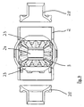
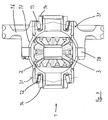
- shows a perspective sectional view of the housing element according to
fig. 4 with the fully assembled and locked bevel gears, followed by the assembly of the end bearings to form a modular differential concept, - Fig. 6
- shows the outside of the arrangement according
fig. 5 , - Fig. 7
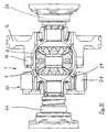
- shows a cross sectional view of the differential with a one-piece drive gear mounted at the housing element according to a first embodiment of the invention, with an assembly guide pin replaced with the final drive pin,
- Fig. 8
- shows the assembly as
fig. 7 with a two-piece drive gear according to a second embodiment of the invention, - Fig. 9
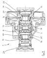
- shows a cross sectional view of the differential mounted in the drive axle or gearbox housing and
- Fig. 10
- shows the option to locate the rotating part of an extra power assist device on the housing element.
-
Fig. 1 shows a tube section 2' made of a tube in cross sectional view. The tube section 2' has a substantially constant outer diameter D0 and a substantially constant wall thickness along its axial extension. From the tube section 2' ahousing element 2 is formed as depicted infig. 2 . - The
housing element 2 is made by plastic deforming the tube section 2' in amiddle section 4. I. e. the tube section 2' remains basically undeformed in theadjacent regions 10 on both sides of themiddle region 4. As can be seen themiddle region 4 is enlarged in diameter and formed to aspherical shape 6. This is done e. g. by exerting an axial pressure to the tube section 2' as illustrated by the arrows infig. 1 . The tube section 2' is axially compressed and an inner pressure is exerted on theinner surface 5 of the tube section 2'. Infig. 1 atool part 22 is shown which is a part of a hydro-forming device. By applying hydraulic pressure to the inner volume of the tube section 2' the material of the tube section 2' of themiddle region 4 is pressed outwards until the outer surface of the tube section 2' get into contact with the cavity surface of thetool part 22. The diameter D0T of thetool part 22 in the side regions is identical with the diameter D0 of the tube section 2'. Thus, the outer circumference of the tube section 2' remains unchanged in the side regions during plastic deformation. - Consequently, the outer diameters D1 and D2 of the
housing element 2 in theadjacent regions 10 remain unchanged compared with the outer diameter D0 of the tube section 2'. However, themiddle region 4 is expanded to a bigger diameter. So a containing chamber 15 is formed having a sufficient volume for receiving a bevel gear. - As can be seen, the
housing element 2 is completely formed from a tube section 2', wherein the diameters D1, D2 of thehousing element 2 in theadjacent regions 10 beside the expandedmiddle section 4 are equal - at least within the normal manufacturing tolerances. - Hydro-forming is a cost-effective way of shaping tube material into stiff and strong pieces. High pressure hydraulic pistons inject a fluid at very high pressure inside the workpiece which causes it to expand until it matches the shape of the mold.
- After the middle region or
middle section 4 has been produced by the hydro-forming process,openings housing element 2 for a purpose which will become apparent later. Furthermore,openings 9 can be machined, e. g. punched, which are uniformly distributed around the circumference of theadjacent region 10. Thoseopenings 9 can be used for sensing the rotational speed of thehousing element 2 by means of a sensor (not depicted). - Furthermore, big circular-shaped
openings 27 can be machined, especially punched out, into thehousing element 2 which reduce the weight of thehousing element 2 and thus of the differential gear. Also, thoseopenings 27 can be used to facilitate the process of mounting the bevel gear described later in the containing chamber 15. The depicted design is usually employed to be lubricated with oil. Consequently, oil can flow through theopenings 27 and to the bevel gear. This design is commonly used in most vehicles. - It is also possible that neither the
openings 9 nor theopenings 27 are realized to thereby obtain a closed and sealed unit with a certain amount of grease in the inner of the containing chamber. - The mounting of the differential gear is shown in
figures 3 till 9, where different stages of the mounting process are depicted. - In
fig. 3 it can be seen thatgear wheels 3', 3", 3"' and 3"" of abevel gear 3 are mounted in the containing chamber 15 of thehousing element 2. The gear wheels 3' is a satellite bevel gear. In a first state plain bearing elements 23 (which can consist of a plain bearing made of plastic or steel material) are located at the inner surface of the sphericalmiddle region 4 of thehousing element 2. Then, the satellite gears 3' and 3"' are placed in the shown position. A guide pin 24 (used for mounting only) is then pushed in the direction of the arrow through thehousing element 2 through theopenings gears wheels 3'. 3"'. Then the sidebevel gear wheels 3" and 3"" are inserted from the sides of thehousing element 2. Also the sidebevel gear wheels 3", 3"" are brought in contact withplain bearing elements 23. - As can be seen in
fig. 4 , after the pre-assembly of thebevel gear 3, theaxial support elements 25 for the side bevel gears are inserted in axial direction contacting theplain bearing elements 23. - As can be seen in
fig. 5 after the mounting of theaxial support elements 25 for the side bevel gears these supports are axially locked in thehousing element 2 by means of cold-forming the punched outlips 11 into a radial groove in the support. This can be done in that way that the desired axial play is maintained. - Two
taper roller bearings 12 and 13 - forming abearing arrangement 12, 13 - are mounted to get the device as shown infigures 5 and6 . While theouter rings 20 of thetaper roller bearings housing elements 2, the stationaryinner rings 21 of thetaper roller bearings fig. 9 ). The outer rings 20 of thetaper roller bearings housing element 2 by common methods. Usually, a press fit is employed. Also, e. g. glueing of the outer ring is possible. - In
figures 5 and6 theguide pin 24 is still in the mounting position. After the pre-assembly is finished theguide pin 24 is pressed out by mounting thefinal drive pin 18. - As can be seen in
fig. 7 adrive gear 16 is attached to thehousing element 2. The one-piece drive gear 16 has a section with aspherical part 17 which is congruent with thespherical shape 6 of themiddle region 4 of thehousing element 3. After thedrive gear 16 is brought into position thedrive pin 18 is pushed through thedrive gear 16 and thehousing element 2 and also through the satellite gears 3', 3'"' of thebevel gear 3. - After the
pin 18 is secured axially (means for this are not depicted) the final mounting stage of the differential 1 has been reached. - The
drive gear 16 runs parallel with the driven gear (not shown) and can be a helical or a spur gear. Alternatively, a right angle transmission can be applied using a drive bevel crown gear on thehousing element 2 cooperating with a mating pinion gear (not shown). - In
fig. 7 it is also depicted that thetaper roller bearings load lines 31 in this figure. - In
fig. 8 an alternative design is shown. Here, thedrive gear 16 is made in a two-part way with a gear wheel 16' and ahub element 16", which are mechanically connected to another by means of e. g. rivets 19. - In
fig. 9 the fully in-line mounteddifferential module 1 is shown ready for assembly into a vehicle. Thecarrier structure 14 is a housing element which bears thewhole differential 1. Thedrive flange elements 26 connected with the wheels of the vehicle are shown which are firmly connected to theaxial support elements 25. These drive flange elements are mounted after assembly of the differential module in the gearbox carrier or drive axle differential carrier. -
Fig. 10 shows an alternative embodiment of the invention, where the rotating part of an extra power assist device on the housing element is mounted. Thepower assist device 30 has substantially astator 28 which is arranged stationary and arotor 29 which is connected to therotating housing element 2. Thus, in the embodiment offig. 10 the power assist device is an electrical/mechanical device. An alternative or additive solution can be a hydraulic/mechanical device. -
- 1
- Differential
- 2
- Housing element
- 2'
- Tube section
- 3
- Bevel gear (satellite bevel gear / side bevel gear)
- 3'
- Gear wheel of the bevel gear (satellite gear)
- 3"
- Gear wheel of the bevel gear (side gear)
- 3"'
- Gear wheel of the bevel gear (satellite gear)
- 3""
- Gear wheel of the bevel gear (side gear)
- 4
- Middle region / middle section of the housing element
- 5
- Inner surface
- 6
- Spherical shape
- 7
- Opening
- 8
- Opening
- 9
- Opening
- 10
- Adjacent region
- 11
- Indentation
- 12, 13
- Bearing arrangement
- 12
- Taper roller bearing
- 13
- Taper roller bearing
- 14
- Carrier structure
- 15
- Containing chamber
- 16
- Drive gear
- 16'
- Gear wheel
- 16"
- Hub element
- 17
- Spherical part
- 18
- Pin (drive pin)
- 19
- Rivet (bolt)
- 20
- Outer Ring
- 21
- Inner Ring
- 22
- Tool Part
- 23
- Plain bearing element
- 24
- Guide pin
- 25
- Axial support element / plain bearing element
- 26
- Drive flange element
- 27
- Opening
- 28
- Stator
- 29
- Rotor
- 30
- Power assist device
- 31
- Load line
- D0
- Diameter
- D0T
- Diameter
- D1
- First diameter
- D2
- Second diameter
Claims (15)
- Method for producing a differential (1), especially for a vehicle, wherein the differential (1) has a housing element (2), in which a bevel gear (3, 3', 3", 3"', 3"") is mountable inside a middle region (4) of the housing element (2),
characterized in
that the housing element (2) is produced from a one piece tube section (2') comprising the middle region (4) and an adjacent region (10) on either side of the middle region (4), wherein only the middle region (4) of the tube section (2') is radially widened by plastic deformation. - Method according to claim 1, characterized in that the plastic deformation process is a hydro-forming process.
- Method according to claim 1, characterized in that the plastic deformation process is a mechanical process.
- Method according to claim 3, characterized in that the mechanical process employs a tool, especially a roller, which is pressed radially against an inner surface (5) of the tube section (2').
- Method according to at least one of claims 1 till 4, characterized in that the deformed middle region (4) is provided with a spherical shape (6) or a cylindrical shape.
- Method according to at least one of claims 1 till 5, characterized in that after or before plastic deformation of the middle region (4) one or two openings (7, 8) are machined, especially punched out, preferably in opposed parts of the radially widened region (4).
- Method according to at least one of claims 1 till 6, characterized in that after or before plastic deformation of the middle region (4) a plurality of openings (9) are machined, especially punched out, in an adjacent region (10) of the radially widened region (4), wherein the openings (9) are uniformly distributed around the circumference of the housing element (2).
- Method according to at least one of claims 1 till 6, characterized in that after or before plastic deformation of the middle region (4) a plurality of indentations or dimples, especially lip shaped dimples, are machined, especially punched out, in an adjacent region (10) of the radially widened region (4), wherein the indentations or dimples are uniformly distributed around the circumference of the housing element (2).
- Method according to at least one of claims 1 till 8, characterized in that an axial fixation of at least one component (3, 3', 3", 3"', 3"") of the differential (1) is carried out by bringing in one or more indentations (11) and/or lip shaped dimples into the outer surface of the housing element (2).
- Differential (1), especially for a vehicle, which has a housing element (2), wherein bevel gears (3, 3', 3", 3"', 3"") are mounted inside a middle region (4) of the housing element (2), wherein the housing element (2) is supported by a bearing arrangement (12, 13) relatively to a carrier structure (14),
characterized in
that the housing element (2) consists of a one piece tube section (2') comprising the middle region (4) and an adjacent region (10) on either side of the middle region (4), wherein only the middle region (4) of the tube section (2') is radially widened by plastic deformation, and wherein the widened middle region (4) forms a containing chamber (15) for the bevel gears (3, 3', 3", 3"', 3""). - Differential according to claim 10, characterized in that the plastic deformation is carried out by hydro-forming or by mechanical forming.
- Differential according to claim 10 or 11, characterized in that the radially widened region (4) of the housing element (2) has a spherical shape (6) or a cylindrical shape.
- Differential according to at least one of claims 10 till 12, characterized in that a drive gear (16) is fixed at the housing element (2).
- Differential according to claim 12 and 13, characterized in that the drive gear (16) has a spherical part (17) which is congruent with the spherical shape (6) of the housing element (2).
- Differential according to claim 13 or 14, characterized in that the drive gear (16) is a helical or spur gear or bevel gear.
Applications Claiming Priority (1)
| Application Number | Priority Date | Filing Date | Title |
|---|---|---|---|
| PCT/EP2006/009652 WO2008040375A1 (en) | 2006-10-05 | 2006-10-05 | Method for producing a differential and differential |
Publications (2)
| Publication Number | Publication Date |
|---|---|
| EP2074339A1 EP2074339A1 (en) | 2009-07-01 |
| EP2074339B1 true EP2074339B1 (en) | 2010-03-31 |
Family
ID=37594973
Family Applications (1)
| Application Number | Title | Priority Date | Filing Date |
|---|---|---|---|
| EP06806061A Not-in-force EP2074339B1 (en) | 2006-10-05 | 2006-10-05 | Method for producing a differential and differential |
Country Status (4)
| Country | Link |
|---|---|
| EP (1) | EP2074339B1 (en) |
| AT (1) | ATE462903T1 (en) |
| DE (1) | DE602006013362D1 (en) |
| WO (1) | WO2008040375A1 (en) |
Cited By (2)
| Publication number | Priority date | Publication date | Assignee | Title |
|---|---|---|---|---|
| DE102011007698A1 (en) * | 2011-04-19 | 2012-10-25 | Neapco Europe Gmbh | Differential for use in differential gearbox of motor car, has housing designed as pipe section, and externally toothed pinion gears rotatably supported in housing and engaged with crown gears |
| WO2024083658A1 (en) * | 2022-10-19 | 2024-04-25 | Audi Ag | Bevel gear differential gearing for a motor vehicle, and method for producing a bevel gear differential gearing |
Families Citing this family (3)
| Publication number | Priority date | Publication date | Assignee | Title |
|---|---|---|---|---|
| DE102010054655B4 (en) | 2010-09-15 | 2012-08-09 | Sona Blw Präzisionsschmiede Gmbh | Differential for motor vehicles |
| EP4382772B1 (en) * | 2022-12-05 | 2026-02-11 | Volvo Car Corporation | Differential gear assembly, drivetrain for a vehicle, method for assembling a differential gear assembly and method for disassembling a differential gear assembly |
| EP4592115A1 (en) * | 2024-01-25 | 2025-07-30 | Volvo Car Corporation | Drive module and axle assembly for an electric vehicle, and electric vehicle |
Family Cites Families (8)
| Publication number | Priority date | Publication date | Assignee | Title |
|---|---|---|---|---|
| GB1252520A (en) * | 1969-10-18 | 1971-11-03 | ||
| DE2844918A1 (en) * | 1978-10-14 | 1980-04-24 | Volkswagenwerk Ag | BEVEL GEAR GEARBOX |
| US5157966A (en) * | 1990-02-20 | 1992-10-27 | The Torrington Company | Transmission speed sensor |
| EP0683333B1 (en) * | 1994-05-18 | 1997-10-01 | Dr.Ing.h.c. F. Porsche Aktiengesellschaft | Axle drive differential for motor vehicles |
| US6061907A (en) * | 1998-08-10 | 2000-05-16 | Ford Global Technologies, Inc. | Method for making a differential mechanism for an automotive vehicle |
| US6692398B1 (en) * | 2001-05-11 | 2004-02-17 | Torque-Traction Technologies, Inc. | Simplified differential assembly |
| CA2508768A1 (en) * | 2002-12-05 | 2004-06-24 | Joseph A. Szuba | Differential mechanism for a vehicle |
| US7461454B2 (en) * | 2003-01-31 | 2008-12-09 | Arvin Technologies | Method of fabricating a housing assembly |
-
2006
- 2006-10-05 AT AT06806061T patent/ATE462903T1/en not_active IP Right Cessation
- 2006-10-05 DE DE602006013362T patent/DE602006013362D1/en active Active
- 2006-10-05 EP EP06806061A patent/EP2074339B1/en not_active Not-in-force
- 2006-10-05 WO PCT/EP2006/009652 patent/WO2008040375A1/en not_active Ceased
Cited By (2)
| Publication number | Priority date | Publication date | Assignee | Title |
|---|---|---|---|---|
| DE102011007698A1 (en) * | 2011-04-19 | 2012-10-25 | Neapco Europe Gmbh | Differential for use in differential gearbox of motor car, has housing designed as pipe section, and externally toothed pinion gears rotatably supported in housing and engaged with crown gears |
| WO2024083658A1 (en) * | 2022-10-19 | 2024-04-25 | Audi Ag | Bevel gear differential gearing for a motor vehicle, and method for producing a bevel gear differential gearing |
Also Published As
| Publication number | Publication date |
|---|---|
| DE602006013362D1 (en) | 2010-05-12 |
| WO2008040375A1 (en) | 2008-04-10 |
| ATE462903T1 (en) | 2010-04-15 |
| EP2074339A1 (en) | 2009-07-01 |
Similar Documents
| Publication | Publication Date | Title |
|---|---|---|
| EP0979959B1 (en) | Method for making a differential mechanism for an automotive vehicle | |
| EP0979958B1 (en) | Housing for a differential mechanism of an automotive vehicle | |
| EP0979960B1 (en) | Method for making a differential mechanism for an automotive vehicle | |
| US6945898B2 (en) | Differential mechanism for a vehicle | |
| CN101344163A (en) | Differential mechanism assembly | |
| US7485065B2 (en) | Producing and maintaining a desired bearing preload in a differential mechanism | |
| US9145963B2 (en) | Planetary gearbox comprising a differential | |
| CA2451893C (en) | Differential housing with integrated ring gear | |
| EP2074339B1 (en) | Method for producing a differential and differential | |
| CA2533930A1 (en) | Pinion support for a differential assembly | |
| US7367914B2 (en) | Differential housing support member | |
| EP1945972B1 (en) | Lightweight differential case half | |
| US20100323841A1 (en) | Differential carrier consisting of half-shells and a process of producing a differential carrier | |
| KR101195901B1 (en) | Pinion unit in axle assembly | |
| JP4344681B2 (en) | Inner rotor type rotating electrical machine | |
| WO2008101719A1 (en) | Differential gear unit | |
| WO2008104198A1 (en) | Differential gear unit | |
| CN114207321B (en) | Compact transmission device with multi-stage planetary gear set and spur gear differential | |
| CN111140643B (en) | Split type main reducer casing of electric drive car and car | |
| JP4515875B2 (en) | Assembly structure of vertical transaxle drive pinion shaft | |
| CN214888742U (en) | Commercial car turns to bevel gear angle reduction gear wheel bearing structure | |
| CN215883191U (en) | Automobile hub assembly and automobile drive axle | |
| RU2799273C1 (en) | Vehicle drive axle reducer | |
| CN112178163A (en) | Axial fixing of planetary gear bolts in planetary gear carrier | |
| KR820000519B1 (en) | Improvements in motor vehicle axles and method of constructing asuch axles |
Legal Events
| Date | Code | Title | Description |
|---|---|---|---|
| PUAI | Public reference made under article 153(3) epc to a published international application that has entered the european phase |
Free format text: ORIGINAL CODE: 0009012 |
|
| 17P | Request for examination filed |
Effective date: 20090506 |
|
| AK | Designated contracting states |
Kind code of ref document: A1 Designated state(s): AT BE BG CH CY CZ DE DK EE ES FI FR GB GR HU IE IS IT LI LT LU LV MC NL PL PT RO SE SI SK TR |
|
| AX | Request for extension of the european patent |
Extension state: AL BA HR MK RS |
|
| GRAP | Despatch of communication of intention to grant a patent |
Free format text: ORIGINAL CODE: EPIDOSNIGR1 |
|
| GRAS | Grant fee paid |
Free format text: ORIGINAL CODE: EPIDOSNIGR3 |
|
| GRAA | (expected) grant |
Free format text: ORIGINAL CODE: 0009210 |
|
| AK | Designated contracting states |
Kind code of ref document: B1 Designated state(s): AT BE BG CH CY CZ DE DK EE ES FI FR GB GR HU IE IS IT LI LT LU LV MC NL PL PT RO SE SI SK TR |
|
| REG | Reference to a national code |
Ref country code: GB Ref legal event code: FG4D Ref country code: CH Ref legal event code: EP |
|
| REG | Reference to a national code |
Ref country code: IE Ref legal event code: FG4D |
|
| REF | Corresponds to: |
Ref document number: 602006013362 Country of ref document: DE Date of ref document: 20100512 Kind code of ref document: P |
|
| REG | Reference to a national code |
Ref country code: NL Ref legal event code: VDEP Effective date: 20100331 |
|
| PG25 | Lapsed in a contracting state [announced via postgrant information from national office to epo] |
Ref country code: LT Free format text: LAPSE BECAUSE OF FAILURE TO SUBMIT A TRANSLATION OF THE DESCRIPTION OR TO PAY THE FEE WITHIN THE PRESCRIBED TIME-LIMIT Effective date: 20100331 |
|
| LTIE | Lt: invalidation of european patent or patent extension |
Effective date: 20100331 |
|
| PG25 | Lapsed in a contracting state [announced via postgrant information from national office to epo] |
Ref country code: SI Free format text: LAPSE BECAUSE OF FAILURE TO SUBMIT A TRANSLATION OF THE DESCRIPTION OR TO PAY THE FEE WITHIN THE PRESCRIBED TIME-LIMIT Effective date: 20100331 Ref country code: LV Free format text: LAPSE BECAUSE OF FAILURE TO SUBMIT A TRANSLATION OF THE DESCRIPTION OR TO PAY THE FEE WITHIN THE PRESCRIBED TIME-LIMIT Effective date: 20100331 Ref country code: FI Free format text: LAPSE BECAUSE OF FAILURE TO SUBMIT A TRANSLATION OF THE DESCRIPTION OR TO PAY THE FEE WITHIN THE PRESCRIBED TIME-LIMIT Effective date: 20100331 Ref country code: AT Free format text: LAPSE BECAUSE OF FAILURE TO SUBMIT A TRANSLATION OF THE DESCRIPTION OR TO PAY THE FEE WITHIN THE PRESCRIBED TIME-LIMIT Effective date: 20100331 Ref country code: PL Free format text: LAPSE BECAUSE OF FAILURE TO SUBMIT A TRANSLATION OF THE DESCRIPTION OR TO PAY THE FEE WITHIN THE PRESCRIBED TIME-LIMIT Effective date: 20100331 |
|
| PG25 | Lapsed in a contracting state [announced via postgrant information from national office to epo] |
Ref country code: RO Free format text: LAPSE BECAUSE OF FAILURE TO SUBMIT A TRANSLATION OF THE DESCRIPTION OR TO PAY THE FEE WITHIN THE PRESCRIBED TIME-LIMIT Effective date: 20100331 Ref country code: ES Free format text: LAPSE BECAUSE OF FAILURE TO SUBMIT A TRANSLATION OF THE DESCRIPTION OR TO PAY THE FEE WITHIN THE PRESCRIBED TIME-LIMIT Effective date: 20100712 Ref country code: EE Free format text: LAPSE BECAUSE OF FAILURE TO SUBMIT A TRANSLATION OF THE DESCRIPTION OR TO PAY THE FEE WITHIN THE PRESCRIBED TIME-LIMIT Effective date: 20100331 Ref country code: CY Free format text: LAPSE BECAUSE OF FAILURE TO SUBMIT A TRANSLATION OF THE DESCRIPTION OR TO PAY THE FEE WITHIN THE PRESCRIBED TIME-LIMIT Effective date: 20100331 Ref country code: BE Free format text: LAPSE BECAUSE OF FAILURE TO SUBMIT A TRANSLATION OF THE DESCRIPTION OR TO PAY THE FEE WITHIN THE PRESCRIBED TIME-LIMIT Effective date: 20100331 Ref country code: NL Free format text: LAPSE BECAUSE OF FAILURE TO SUBMIT A TRANSLATION OF THE DESCRIPTION OR TO PAY THE FEE WITHIN THE PRESCRIBED TIME-LIMIT Effective date: 20100331 Ref country code: SE Free format text: LAPSE BECAUSE OF FAILURE TO SUBMIT A TRANSLATION OF THE DESCRIPTION OR TO PAY THE FEE WITHIN THE PRESCRIBED TIME-LIMIT Effective date: 20100331 |
|
| PG25 | Lapsed in a contracting state [announced via postgrant information from national office to epo] |
Ref country code: CZ Free format text: LAPSE BECAUSE OF FAILURE TO SUBMIT A TRANSLATION OF THE DESCRIPTION OR TO PAY THE FEE WITHIN THE PRESCRIBED TIME-LIMIT Effective date: 20100331 Ref country code: IS Free format text: LAPSE BECAUSE OF FAILURE TO SUBMIT A TRANSLATION OF THE DESCRIPTION OR TO PAY THE FEE WITHIN THE PRESCRIBED TIME-LIMIT Effective date: 20100731 Ref country code: SK Free format text: LAPSE BECAUSE OF FAILURE TO SUBMIT A TRANSLATION OF THE DESCRIPTION OR TO PAY THE FEE WITHIN THE PRESCRIBED TIME-LIMIT Effective date: 20100331 |
|
| PG25 | Lapsed in a contracting state [announced via postgrant information from national office to epo] |
Ref country code: PT Free format text: LAPSE BECAUSE OF FAILURE TO SUBMIT A TRANSLATION OF THE DESCRIPTION OR TO PAY THE FEE WITHIN THE PRESCRIBED TIME-LIMIT Effective date: 20100802 Ref country code: DK Free format text: LAPSE BECAUSE OF FAILURE TO SUBMIT A TRANSLATION OF THE DESCRIPTION OR TO PAY THE FEE WITHIN THE PRESCRIBED TIME-LIMIT Effective date: 20100331 |
|
| PLBE | No opposition filed within time limit |
Free format text: ORIGINAL CODE: 0009261 |
|
| STAA | Information on the status of an ep patent application or granted ep patent |
Free format text: STATUS: NO OPPOSITION FILED WITHIN TIME LIMIT |
|
| 26N | No opposition filed |
Effective date: 20110104 |
|
| PG25 | Lapsed in a contracting state [announced via postgrant information from national office to epo] |
Ref country code: IT Free format text: LAPSE BECAUSE OF FAILURE TO SUBMIT A TRANSLATION OF THE DESCRIPTION OR TO PAY THE FEE WITHIN THE PRESCRIBED TIME-LIMIT Effective date: 20100331 |
|
| PG25 | Lapsed in a contracting state [announced via postgrant information from national office to epo] |
Ref country code: MC Free format text: LAPSE BECAUSE OF NON-PAYMENT OF DUE FEES Effective date: 20101031 |
|
| REG | Reference to a national code |
Ref country code: CH Ref legal event code: PL |
|
| GBPC | Gb: european patent ceased through non-payment of renewal fee |
Effective date: 20101005 |
|
| PG25 | Lapsed in a contracting state [announced via postgrant information from national office to epo] |
Ref country code: LI Free format text: LAPSE BECAUSE OF NON-PAYMENT OF DUE FEES Effective date: 20101031 Ref country code: CH Free format text: LAPSE BECAUSE OF NON-PAYMENT OF DUE FEES Effective date: 20101031 Ref country code: FR Free format text: LAPSE BECAUSE OF NON-PAYMENT OF DUE FEES Effective date: 20101102 |
|
| REG | Reference to a national code |
Ref country code: FR Ref legal event code: ST Effective date: 20110630 |
|
| PG25 | Lapsed in a contracting state [announced via postgrant information from national office to epo] |
Ref country code: GB Free format text: LAPSE BECAUSE OF NON-PAYMENT OF DUE FEES Effective date: 20101005 |
|
| PG25 | Lapsed in a contracting state [announced via postgrant information from national office to epo] |
Ref country code: IE Free format text: LAPSE BECAUSE OF NON-PAYMENT OF DUE FEES Effective date: 20101005 |
|
| PG25 | Lapsed in a contracting state [announced via postgrant information from national office to epo] |
Ref country code: LU Free format text: LAPSE BECAUSE OF NON-PAYMENT OF DUE FEES Effective date: 20101005 Ref country code: HU Free format text: LAPSE BECAUSE OF FAILURE TO SUBMIT A TRANSLATION OF THE DESCRIPTION OR TO PAY THE FEE WITHIN THE PRESCRIBED TIME-LIMIT Effective date: 20101001 Ref country code: BG Free format text: LAPSE BECAUSE OF FAILURE TO SUBMIT A TRANSLATION OF THE DESCRIPTION OR TO PAY THE FEE WITHIN THE PRESCRIBED TIME-LIMIT Effective date: 20100331 |
|
| PG25 | Lapsed in a contracting state [announced via postgrant information from national office to epo] |
Ref country code: TR Free format text: LAPSE BECAUSE OF FAILURE TO SUBMIT A TRANSLATION OF THE DESCRIPTION OR TO PAY THE FEE WITHIN THE PRESCRIBED TIME-LIMIT Effective date: 20100331 |
|
| PG25 | Lapsed in a contracting state [announced via postgrant information from national office to epo] |
Ref country code: BG Free format text: LAPSE BECAUSE OF FAILURE TO SUBMIT A TRANSLATION OF THE DESCRIPTION OR TO PAY THE FEE WITHIN THE PRESCRIBED TIME-LIMIT Effective date: 20100630 |
|
| PG25 | Lapsed in a contracting state [announced via postgrant information from national office to epo] |
Ref country code: GR Free format text: LAPSE BECAUSE OF FAILURE TO SUBMIT A TRANSLATION OF THE DESCRIPTION OR TO PAY THE FEE WITHIN THE PRESCRIBED TIME-LIMIT Effective date: 20100331 |
|
| PGFP | Annual fee paid to national office [announced via postgrant information from national office to epo] |
Ref country code: DE Payment date: 20151230 Year of fee payment: 10 |
|
| REG | Reference to a national code |
Ref country code: DE Ref legal event code: R119 Ref document number: 602006013362 Country of ref document: DE |
|
| PG25 | Lapsed in a contracting state [announced via postgrant information from national office to epo] |
Ref country code: DE Free format text: LAPSE BECAUSE OF NON-PAYMENT OF DUE FEES Effective date: 20170503 |