EP2075494A1 - Valve and hydrant. - Google Patents
Valve and hydrant. Download PDFInfo
- Publication number
- EP2075494A1 EP2075494A1 EP07124070A EP07124070A EP2075494A1 EP 2075494 A1 EP2075494 A1 EP 2075494A1 EP 07124070 A EP07124070 A EP 07124070A EP 07124070 A EP07124070 A EP 07124070A EP 2075494 A1 EP2075494 A1 EP 2075494A1
- Authority
- EP
- European Patent Office
- Prior art keywords
- valve
- valve body
- hydrant
- valve seat
- drain hole
- Prior art date
- Legal status (The legal status is an assumption and is not a legal conclusion. Google has not performed a legal analysis and makes no representation as to the accuracy of the status listed.)
- Granted
Links
- XLYOFNOQVPJJNP-UHFFFAOYSA-N water Substances O XLYOFNOQVPJJNP-UHFFFAOYSA-N 0.000 claims abstract description 17
- 238000007789 sealing Methods 0.000 claims abstract description 11
- 238000006073 displacement reaction Methods 0.000 claims abstract description 7
- 239000011248 coating agent Substances 0.000 claims description 12
- 238000000576 coating method Methods 0.000 claims description 12
- 239000003651 drinking water Substances 0.000 claims description 7
- 235000020188 drinking water Nutrition 0.000 claims description 7
- 239000007788 liquid Substances 0.000 description 7
- 210000005069 ears Anatomy 0.000 description 6
- 238000012423 maintenance Methods 0.000 description 5
- 239000000463 material Substances 0.000 description 4
- 229920003051 synthetic elastomer Polymers 0.000 description 4
- 230000007797 corrosion Effects 0.000 description 3
- 238000005260 corrosion Methods 0.000 description 3
- 229920003052 natural elastomer Polymers 0.000 description 3
- 229920001194 natural rubber Polymers 0.000 description 3
- 229910001018 Cast iron Inorganic materials 0.000 description 2
- 230000000295 complement effect Effects 0.000 description 2
- 239000013536 elastomeric material Substances 0.000 description 2
- 238000004519 manufacturing process Methods 0.000 description 2
- 229910001369 Brass Inorganic materials 0.000 description 1
- 230000000903 blocking effect Effects 0.000 description 1
- 239000010951 brass Substances 0.000 description 1
- 239000000428 dust Substances 0.000 description 1
- 230000008014 freezing Effects 0.000 description 1
- 238000007710 freezing Methods 0.000 description 1
- 238000009434 installation Methods 0.000 description 1
- 238000003754 machining Methods 0.000 description 1
- 238000012986 modification Methods 0.000 description 1
- 230000004048 modification Effects 0.000 description 1
- 230000008439 repair process Effects 0.000 description 1
- 229910001220 stainless steel Inorganic materials 0.000 description 1
- 239000010935 stainless steel Substances 0.000 description 1
Images

Classifications
-
- E—FIXED CONSTRUCTIONS
- E03—WATER SUPPLY; SEWERAGE
- E03B—INSTALLATIONS OR METHODS FOR OBTAINING, COLLECTING, OR DISTRIBUTING WATER
- E03B9/00—Methods or installations for drawing-off water
- E03B9/02—Hydrants; Arrangements of valves therein; Keys for hydrants
- E03B9/08—Underground hydrants
-
- E—FIXED CONSTRUCTIONS
- E03—WATER SUPPLY; SEWERAGE
- E03B—INSTALLATIONS OR METHODS FOR OBTAINING, COLLECTING, OR DISTRIBUTING WATER
- E03B9/00—Methods or installations for drawing-off water
- E03B9/02—Hydrants; Arrangements of valves therein; Keys for hydrants
- E03B9/14—Draining devices for hydrants
-
- F—MECHANICAL ENGINEERING; LIGHTING; HEATING; WEAPONS; BLASTING
- F16—ENGINEERING ELEMENTS AND UNITS; GENERAL MEASURES FOR PRODUCING AND MAINTAINING EFFECTIVE FUNCTIONING OF MACHINES OR INSTALLATIONS; THERMAL INSULATION IN GENERAL
- F16K—VALVES; TAPS; COCKS; ACTUATING-FLOATS; DEVICES FOR VENTING OR AERATING
- F16K1/00—Lift valves or globe valves, i.e. cut-off apparatus with closure members having at least a component of their opening and closing motion perpendicular to the closing faces
- F16K1/32—Details
- F16K1/34—Cutting-off parts, e.g. valve members, seats
- F16K1/36—Valve members
-
- F—MECHANICAL ENGINEERING; LIGHTING; HEATING; WEAPONS; BLASTING
- F16—ENGINEERING ELEMENTS AND UNITS; GENERAL MEASURES FOR PRODUCING AND MAINTAINING EFFECTIVE FUNCTIONING OF MACHINES OR INSTALLATIONS; THERMAL INSULATION IN GENERAL
- F16K—VALVES; TAPS; COCKS; ACTUATING-FLOATS; DEVICES FOR VENTING OR AERATING
- F16K27/00—Construction of housing; Use of materials therefor
- F16K27/006—Construction of housing; Use of materials therefor of hydrants
-
- E—FIXED CONSTRUCTIONS
- E03—WATER SUPPLY; SEWERAGE
- E03B—INSTALLATIONS OR METHODS FOR OBTAINING, COLLECTING, OR DISTRIBUTING WATER
- E03B9/00—Methods or installations for drawing-off water
- E03B9/02—Hydrants; Arrangements of valves therein; Keys for hydrants
- E03B2009/022—Hydrants with a tubular valve seat
Definitions
- the present invention relates to a valve, in particular a water valve for a hydrant.
- Such hydrants comprise a hollow body connected to a water supply through a spindle-operated valve below the hollow body. To prevent that, after the valve has been opened and closed again, water remains within the hollow body, the hydrant is normally provided with a drain hole for draining the remaining water from the hollow body. This is particularly necessary in cold climates in which freezing water could burst said hollow body and/or damage the valve.
- the top of the valve body is provided with an extension that will seal the drain hole when said valve body is displaced towards its open position.
- a hydrant was disclosed in the International Patent Applications WO 02/35019 and WO 02/075062 with two valves: a main valve with a cylindrical valve seat and a non-return valve below said main valve, with a spherical valve body.
- the higher complexity of such a hydrant is however a significant drawback, in terms of cost, reliability, and ease of maintenance.
- German patent application publication DE 26 21 163 This prior art valve comprises a valve seat and a valve body displaceable in an axis between a lower position in which said valve body fits against the valve seat, thus closing the valve, and a higher position in which the valve is open.
- the valve seat comprises an axial surface substantially parallel to said axis of displacement of the valve body, and a drain hole perforated in said first surface of the valve seat.
- the valve body comprises a top, a bottom, an axial surface between said top and bottom, with a substantially tight fit with said axial surface of the valve seat, a drainage canal between said top and said axial surface of the valve body for connecting said top with said drain hole when the valve body is in its lower position, and at least two extensions at the bottom for axially guiding said valve body and sealing said drain hole when the valve body is in said higher position.
- the purpose of the present invention is thus that of ensuring an improved valve which allows a complete drainage of liquid above it, yet has better leak-tightness and easier maintenance than those of the
- the seat of the valve of the invention further comprises an upper surface, above its axial surface and at a substantial angle with respect to said axis of displacement of said valve body, and said valve body also comprises another surface substantially fitting said upper surface of the valve seat. It becomes thus possible to exert an axial pressure between valve body and valve seat for a tighter fit of the valve to complement that between the axial surfaces of valve body and valve seat.
- said extensions at the bottom of the valve body may be substantially rigid.
- those extensions are preferably in a number of two, with a hard core, for instance metallic, and a soft coating, for instance elastomeric, from a natural elastomer, a synthetic elastomer, or a combination thereof.
- the two extensions ensure the axial guidance of the valve body, whereas one of them covers the drain hole in the valve seat when the valve body is in the open position, thus sealing said drain hole, and preventing that a substantial part of the water going through the valve and the hydrant when the valve is open escapes through said drain hole.
- said extensions at the bottom of the valve body may be at least three, preferably at least four, and one of them, sealing said drain hole when the valve body is in its higher position, may be substantially flexible, whereas the others may be substantially rigid. Said substantially flexible extension being pushed outwardly by the water pressure, it will ensure a superior seal compared with a rigid extension. At least two other, substantially rigid extensions are needed in order to ensure the proper axial guidance of the valve body.
- the two substantially rigid extensions have a hard core, for instance metallic, and a soft coating, for instance elastomeric, from a natural elastomer, a synthetic elastomer, or a combination thereof; whereas the substantially flexible extension is substantially integrally made of said elastomeric material or combination of materials.
- said opening may be formed in a small sunk area in said top of said valve body.
- said valve body may comprise a hard core, for example metallic, and a soft coating, for example elastomeric, and preferably suitable for contact with drinking water.
- said elastomeric coating may comprise a natural elastomer, a synthetic elastomer, or a combination thereof.
- said coating is to be suitable for contact with drinking water, this choice may be restricted to certain synthetic elastomers.
- the valve of the invention will be suitable for use in hydrants in certain regions where hydrants are connected to the drinking water supply.
- a soft coating of the valve body ensures a better fit with the valve seat, while the hard core prevents an excessive deformation of the valve body by the valve closing forces and/or the water pressure.
- said axial surfaces may be substantially cylindrical and said additional surfaces may be substantially conical or spherical.
- Such shapes can be more easily manufactured, for instance with a lathe.
- the present invention also relates to a hydrant comprising a hollow body on top of a valve according to the invention.
- a hydrant comprising a hollow body on top of a valve according to the invention.
- said hydrant may comprise a rod, preferably connected to a spindle, within said hollow body to move said valve body within said higher and lower positions.
- a rod preferably connected to a spindle
- This provides a practical command means for opening and closing the valve from above the hollow body, in particular in underground hydrants.
- With a spindle it will be possible to actuate an axial movement of the rod to open and close the valve with a rotation of the spindle using a comparatively light torque.
- valve seat may be integrally formed within said hollow body. This arrangement would benefit from low production costs.
- said valve seat is formed in an inner sleeve press-fit within said hydrant.
- the hollow body is produced from cast iron, its corrosion resistance may be inadequate for a valve seat.
- a valve seat of a more corrosion-resistant material such as for instance stainless steel or brass, in a bore in said hollow body or in a separate part of said hydrant.
- forming the valve seat in such a sleeve smaller than the hollow body of the hydrant facilitates an improvement in the manufacturing tolerances of the valve seat.
- said valve may be separate from, and releasably attached to, the hollow body. This can be advantageous for facilitating the maintenance and exchange of the valve in, for instance, a hydrant installed over the ground.
- Fig. 1 illustrates a hydrant 1, in particular for underground installation.
- the hydrant 1 comprises a hollow body 2 and a valve 3 below it for connecting the hydrant 1 to a water supply.
- the hollow body 2 comprises a nozzle 4, to tap the water from the hydrant 1, and a spindle 5, that can be turned from the outside of the hydrant 1, and is connected to a rod 6 axially attached to a valve body 7 of the valve 3 for opening and closing said valve 3.
- the valve 3 comprises said valve body 7 and a valve seat 8.
- the valve body 7, which is displaceable along an axis Z to open and close the valve 2, has a top 9, a bottom 10 and, between them, an upper, conical surface and a lower, cylindrical surface.
- the valve seat 8 also comprises complementary, closely fitting upper and lower surfaces, which in this embodiment are directly formed, by instance by machining, in the hollow body 2.
- the valve body 7 is formed by a hard, metallic core 11 covered with a soft, elastomeric coating 12. When the hydrant 1 is to be connected to a drinking water supply, the material of the coating 16 should of course be suitable for contact with drinking water.
- the valve body 7 also comprises two extensions, or ears 13 and 14, below the bottom 10. The core 11 also extends into both these ears 13, 14, so that both are substantially rigid, so as to guide the valve body 7 in an axial movement within the valve 3.
- valve seat 8 The lower, cylindrical surface of the valve seat 8 is perforated by a drain hole 15 leading to the exterior of the hydrant 1.
- a drainage canal 16 connects the top 9 of the valve body 7 with its lower, cylindrical surface.
- Figs. 2a to 2c illustrate the operation of the valve 3.
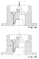
- the valve 3 When the valve 3 is closed, as illustrated in Fig. 2a , the drainage canal 16 is aligned with the drain hole 15, and any liquid above the valve body 7 can drain through the drainage canal 16 and hole 15 and out of the hydrant 1.
- the upper, conical surface and lower, cylindrical surface of the valve body 7 fit closely against the corresponding surfaces of the valve seat 8.
- the upper, conical surfaces of, respectively, the valve body 7 and seat 8 can form together a tight, uninterrupted seal that can be secured by an axial force 17 pushing the valve body 7 and seat 8 together.
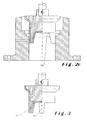
- Fig. 2c illustrates an open position of the valve 3, in which the valve body 7 is axially displaced further upwards, so that the cylindrical surfaces are also brought out of engagement and liquid can flow through the valve 3, namely through openings 18 between the valve body 7 and seat 8.
- the ears 13 and 14, however, remain in contact with the cylindrical surface of the valve seat 8, so as to guide the valve body 7 in its axial movement.
- the ear 13 facing the drain hole 15 seals said drain hole 15 and prevents that part of the liquid flowing through the valve 3 is diverted through said drain hole 15.
- valve 3 can be closed again, through the position illustrated in Fig. 2b , back to the position illustrated in Fig. 2a .
- the drain hole 15 then remains closed until it is aligned with the drainage canal 16 in the valve body 7, when substantially all the liquid remaining above the valve body 7, for instance within the hollow body 2, will be drained through said drainage canal 16 and drain hole 15.
- the valve body 7 comprises three extensions below its bottom 10, namely a sealing ear 13 and two guiding ears 14.
- the hard, metallic core 11 extends into the two guiding ears 14, which will thus also be substantially rigid, but not into the sealing ear 13, which will be integrally made of the soft, elastomeric material of the coating 12, and thus be substantially flexible.
- this sealing ear 13 will face the drain hole 15 so as to seal it.
- the liquid pressure will press the sealing ear 13 against the drain hole 15, achieving a better seal.
- three or more guiding ears 14 may be used instead of just two.
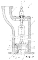
- valve seat 8 is not directly formed in the hollow body 2. Because the hollow body 2 will normally be made of cast iron, a more corrosion-resistant material may be advantageous for the valve seat 8. For this reason, the valve seat 8 is formed in a sleeve 19 press-fit in a bore of the hollow body 2.
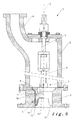
- the whole valve 3 is separate from the hollow body 2 and bolted to it.
- the whole valve 3 may so be removed from the hydrant 2 for replacement or maintenance.
Landscapes
- Engineering & Computer Science (AREA)
- General Engineering & Computer Science (AREA)
- Health & Medical Sciences (AREA)
- Life Sciences & Earth Sciences (AREA)
- Hydrology & Water Resources (AREA)
- Public Health (AREA)
- Water Supply & Treatment (AREA)
- Mechanical Engineering (AREA)
- Lift Valve (AREA)
- Sliding Valves (AREA)
Abstract
Description
- The present invention relates to a valve, in particular a water valve for a hydrant.
- Such hydrants comprise a hollow body connected to a water supply through a spindle-operated valve below the hollow body. To prevent that, after the valve has been opened and closed again, water remains within the hollow body, the hydrant is normally provided with a drain hole for draining the remaining water from the hollow body. This is particularly necessary in cold climates in which freezing water could burst said hollow body and/or damage the valve.
- However, when the valve is opened, it is normally necessary to seal the drain hole to prevent that at least part of the water arriving at high pressure from the water supply leaks through the drain hole. For this purpose, in a number of prior art hydrants, such as, for instance, that disclosed in the
British patent GB 1 281 982 - Such a valve does however have several drawbacks. Its main drawback is that the drain hole will necessarily be placed at some height above the valve body. Therefore, the water within the hollow body will not be completely drained. Recent regulations, notably the European standards EN 14384, EN 14339:2005 and EN 1074-6 for above- and underground hydrants, have however restricted the amount of water that can remain within the hollow body to less than 100 ml.
- To try to solve this problem, a hydrant was disclosed in the International Patent Applications
WO 02/35019 WO 02/075062 - An alternative hydrant valve was disclosed in US Patents
US 5,368,064 andUS 5,441,074 , with a conical valve seat, and a valve body with a drainage canal for connecting the hollow body with the drain hole when the valve body is in the closed position and two extensions provided on top of the valve body for guiding the valve body and sealing the drain hole when the valve is open. However, in this prior art valve, the valve body is displaced downwardly to open the valve. As a result, it is not possible to replace the valve body through the hollow body of the hydrant, for instance for repairs or maintenance after the valve has been mounted underground. This hydrant is thus not in conformity with current European standards either. - Instead, for a more complete drainage of the water within the hollow body, another valve was disclosed in German patent application publication
DE 26 21 163 . This prior art valve comprises a valve seat and a valve body displaceable in an axis between a lower position in which said valve body fits against the valve seat, thus closing the valve, and a higher position in which the valve is open. The valve seat comprises an axial surface substantially parallel to said axis of displacement of the valve body, and a drain hole perforated in said first surface of the valve seat. The valve body comprises a top, a bottom, an axial surface between said top and bottom, with a substantially tight fit with said axial surface of the valve seat, a drainage canal between said top and said axial surface of the valve body for connecting said top with said drain hole when the valve body is in its lower position, and at least two extensions at the bottom for axially guiding said valve body and sealing said drain hole when the valve body is in said higher position. - However, having only an axial valve seat surface has significant drawbacks. In particular, debris such as shavings, pebbles, dust, etc., caught between the valve body and the valve seat may cause scratches in the valve body and/or the valve seat when the valve body moves axially between its closed and open positions. Such scratches can impair the leak-tightness of the valve significantly, defeating the whole purpose of the drain hole.
- The purpose of the present invention is thus that of ensuring an improved valve which allows a complete drainage of liquid above it, yet has better leak-tightness and easier maintenance than those of the
- In order to achieve this, the seat of the valve of the invention further comprises an upper surface, above its axial surface and at a substantial angle with respect to said axis of displacement of said valve body, and said valve body also comprises another surface substantially fitting said upper surface of the valve seat. It becomes thus possible to exert an axial pressure between valve body and valve seat for a tighter fit of the valve to complement that between the axial surfaces of valve body and valve seat.
- In a particular embodiment, said extensions at the bottom of the valve body may be substantially rigid. In this case, those extensions are preferably in a number of two, with a hard core, for instance metallic, and a soft coating, for instance elastomeric, from a natural elastomer, a synthetic elastomer, or a combination thereof. Together, the two extensions ensure the axial guidance of the valve body, whereas one of them covers the drain hole in the valve seat when the valve body is in the open position, thus sealing said drain hole, and preventing that a substantial part of the water going through the valve and the hydrant when the valve is open escapes through said drain hole.
- In an alternative embodiment, said extensions at the bottom of the valve body may be at least three, preferably at least four, and one of them, sealing said drain hole when the valve body is in its higher position, may be substantially flexible, whereas the others may be substantially rigid. Said substantially flexible extension being pushed outwardly by the water pressure, it will ensure a superior seal compared with a rigid extension. At least two other, substantially rigid extensions are needed in order to ensure the proper axial guidance of the valve body. Preferably, the two substantially rigid extensions have a hard core, for instance metallic, and a soft coating, for instance elastomeric, from a natural elastomer, a synthetic elastomer, or a combination thereof; whereas the substantially flexible extension is substantially integrally made of said elastomeric material or combination of materials.
- Preferably, to prevent debris from blocking the opening of the drainage canal to the top of said valve body, said opening may be formed in a small sunk area in said top of said valve body.
- Advantageously, said valve body may comprise a hard core, for example metallic, and a soft coating, for example elastomeric, and preferably suitable for contact with drinking water. As above, said elastomeric coating may comprise a natural elastomer, a synthetic elastomer, or a combination thereof. However, if said coating is to be suitable for contact with drinking water, this choice may be restricted to certain synthetic elastomers. If said soft coating is suitable for contact with drinking water, the valve of the invention will be suitable for use in hydrants in certain regions where hydrants are connected to the drinking water supply. A soft coating of the valve body ensures a better fit with the valve seat, while the hard core prevents an excessive deformation of the valve body by the valve closing forces and/or the water pressure.
- Advantageously, said axial surfaces may be substantially cylindrical and said additional surfaces may be substantially conical or spherical. Such shapes can be more easily manufactured, for instance with a lathe.
- The present invention also relates to a hydrant comprising a hollow body on top of a valve according to the invention. With the valve of the invention, the hollow body will be completely drained after use of the hydrant ensuring its safety in cold climates.
- Advantageously, said hydrant may comprise a rod, preferably connected to a spindle, within said hollow body to move said valve body within said higher and lower positions. This provides a practical command means for opening and closing the valve from above the hollow body, in particular in underground hydrants. With a spindle, it will be possible to actuate an axial movement of the rod to open and close the valve with a rotation of the spindle using a comparatively light torque.
- In a particular embodiment, said valve seat may be integrally formed within said hollow body. This arrangement would benefit from low production costs.
- In an alternative embodiment, said valve seat is formed in an inner sleeve press-fit within said hydrant. In particular if the hollow body is produced from cast iron, its corrosion resistance may be inadequate for a valve seat. For this reason it can be advantageous to press-fit a valve seat of a more corrosion-resistant material, such as for instance stainless steel or brass, in a bore in said hollow body or in a separate part of said hydrant. Moreover, forming the valve seat in such a sleeve smaller than the hollow body of the hydrant facilitates an improvement in the manufacturing tolerances of the valve seat.
- In another alternative embodiment, said valve may be separate from, and releasably attached to, the hollow body. This can be advantageous for facilitating the maintenance and exchange of the valve in, for instance, a hydrant installed over the ground.
- Several embodiments of the invention will be described in detail, but not restrictively, with reference to the accompanying figures, in which:
-
Fig. 1 shows an embodiment of a hydrant according to the invention; -
Fig. 2a shows schematically an embodiment of a valve according to the invention in its closed position; -
Fig. 2b shows schematically the same embodiment of a valve according to the invention between its closed and its open position; -
Fig. 2c shows schematically the same embodiment of a valve according to the invention in its open position; -
Fig. 3 shows the valve body of an alternative embodiment of the valve according to the invention; -
Fig. 4 shows an alternative embodiment of a hydrant according to the invention; and -
Fig. 5 shows another alternative embodiment of a hydrant according to the invention. -
Fig. 1 illustrates ahydrant 1, in particular for underground installation. Thehydrant 1 comprises ahollow body 2 and avalve 3 below it for connecting thehydrant 1 to a water supply. Thehollow body 2 comprises anozzle 4, to tap the water from thehydrant 1, and aspindle 5, that can be turned from the outside of thehydrant 1, and is connected to arod 6 axially attached to avalve body 7 of thevalve 3 for opening and closing saidvalve 3. Thevalve 3 comprises saidvalve body 7 and avalve seat 8. Thevalve body 7, which is displaceable along an axis Z to open and close thevalve 2, has a top 9, a bottom 10 and, between them, an upper, conical surface and a lower, cylindrical surface. Thevalve seat 8 also comprises complementary, closely fitting upper and lower surfaces, which in this embodiment are directly formed, by instance by machining, in thehollow body 2. - The
valve body 7 is formed by a hard,metallic core 11 covered with a soft,elastomeric coating 12. When thehydrant 1 is to be connected to a drinking water supply, the material of thecoating 16 should of course be suitable for contact with drinking water. Thevalve body 7 also comprises two extensions, orears ears valve body 7 in an axial movement within thevalve 3. - The lower, cylindrical surface of the
valve seat 8 is perforated by adrain hole 15 leading to the exterior of thehydrant 1. Within thevalve body 7, adrainage canal 16 connects thetop 9 of thevalve body 7 with its lower, cylindrical surface. -
Figs. 2a to 2c illustrate the operation of thevalve 3. When thevalve 3 is closed, as illustrated inFig. 2a , thedrainage canal 16 is aligned with thedrain hole 15, and any liquid above thevalve body 7 can drain through thedrainage canal 16 andhole 15 and out of thehydrant 1. In this closed position, the upper, conical surface and lower, cylindrical surface of thevalve body 7 fit closely against the corresponding surfaces of thevalve seat 8. In particular, the upper, conical surfaces of, respectively, thevalve body 7 andseat 8 can form together a tight, uninterrupted seal that can be secured by anaxial force 17 pushing thevalve body 7 andseat 8 together. - As illustrated in
Fig. 2b , when thevalve 3 starts to open, for instance by an axial movement of therod 6, pulled by rotation of thespindle 5, the conical surfaces are brought out of engagement with each other. However, the cylindrical surfaces, which are substantially parallel to the axis Z, remain in contact, substantially preventing the flow of liquid through thevalve 3, at least until thedrainage canal 16 andhole 15 are no longer connected. -
Fig. 2c illustrates an open position of thevalve 3, in which thevalve body 7 is axially displaced further upwards, so that the cylindrical surfaces are also brought out of engagement and liquid can flow through thevalve 3, namely throughopenings 18 between thevalve body 7 andseat 8. Theears valve seat 8, so as to guide thevalve body 7 in its axial movement. Moreover, theear 13 facing thedrain hole 15 seals saiddrain hole 15 and prevents that part of the liquid flowing through thevalve 3 is diverted through saiddrain hole 15. - Once open, as in
Fig. 2c , thevalve 3 can be closed again, through the position illustrated inFig. 2b , back to the position illustrated inFig. 2a . Thedrain hole 15 then remains closed until it is aligned with thedrainage canal 16 in thevalve body 7, when substantially all the liquid remaining above thevalve body 7, for instance within thehollow body 2, will be drained through saiddrainage canal 16 anddrain hole 15. - In the alternative embodiment illustrated in
Fig. 3 , thevalve body 7 comprises three extensions below its bottom 10, namely a sealingear 13 and two guidingears 14. In this embodiment, the hard,metallic core 11 extends into the two guidingears 14, which will thus also be substantially rigid, but not into the sealingear 13, which will be integrally made of the soft, elastomeric material of thecoating 12, and thus be substantially flexible. In theopen valve 2, this sealingear 13 will face thedrain hole 15 so as to seal it. With this embodiment, the liquid pressure will press the sealingear 13 against thedrain hole 15, achieving a better seal. For better stability and guidance of thevalve body 7, three or more guidingears 14 may be used instead of just two. - In the alternative embodiment of the
hydrant 1 illustrated inFig. 4 , thevalve seat 8 is not directly formed in thehollow body 2. Because thehollow body 2 will normally be made of cast iron, a more corrosion-resistant material may be advantageous for thevalve seat 8. For this reason, thevalve seat 8 is formed in asleeve 19 press-fit in a bore of thehollow body 2. - In another alternative embodiment, illustrated in
Fig. 5 , thewhole valve 3 is separate from thehollow body 2 and bolted to it. Thewhole valve 3 may so be removed from thehydrant 2 for replacement or maintenance. - Although the present invention has been described with reference to specific exemplary embodiments, it will be evident that various modifications and changes may be made to these embodiments without departing from the broader scope of the invention as set forth in the claims. Accordingly, the description and drawings are to be regarded in an illustrative sense rather than a restrictive sense.
-
- 1
- Hydrant
- 2
- Hollow body
- 3
- Valve
- 4
- Nozzle
- 5
- Spindle
- 6
- Rod
- 7
- Valve body
- 8
- Valve seat
- 9
- Top
- 10
- Bottom
- 11
- Core
- 12
- Coating
- 13
- Ear
- 14
- Ear
- 15
- Drain hole
- 16
- Drainage canal
- 17
- Axial force
- 18
- Openings
- 19
- Sleeve
- Z
- Displacement axis
Claims (10)
- A valve (3), in particular a water valve (3) for a hydrant (1), said valve (3) comprising a valve seat (8) and a valve body (7) displaceable in an axis (Z) between a lower position in which said valve body (7) fits against the valve seat (8), thus closing the valve (3), and a higher position in which the valve (3) is open, wherein:- said valve seat (8) comprises an axial surface substantially parallel to said axis (Z) of displacement of the valve body (7), and a drain hole (15) perforated in said axial surface of the valve seat (8); and- said valve body (7) comprises a top (9), a bottom (10), an axial surface between said top (9) and bottom (10), closely fitting said axial surface of the valve seat (8), a drainage canal (16) between said top (9) and said axial surface of the valve body (7) for connecting said top (9) with said drain hole (15) when the valve body (7) is in its lower position, and at least two extensions (13,14) at the bottom (10) for axially guiding said valve body (7) and sealing said drain hole (15) when the valve body (7) is in said higher position; andcharacterised in that said valve seat (8) further comprises an additional surface, above its axial surface and at a substantial angle with respect to said axis of displacement (Z) of said valve body (7), and said valve body (7) also comprises another additional surface closely fitting said additional surface of the valve seat (8).
- A valve (3) according to claim 1, wherein said extensions (13,14) at the bottom (10) of the valve body (7) are substantially rigid.
- A valve (3) according to claim 1, wherein said extensions (13,14) at the bottom (10) of the valve body (7) are at least three, preferably four, and one (13) of them, sealing said drain hole (15) when the valve body (7) is in its higher position, is substantially flexible, whereas the others (14) are substantially rigid.
- A valve (3) according to any one of the previous claims, wherein said valve body (7) comprises a hard core (11), for example metallic, and a soft coating (12), for example elastomeric, and preferably suitable for contact with drinking water.
- A valve (3) according to any one of the previous claims, wherein said axial surfaces are substantially cylindrical and said additional surfaces are substantially conical or spherical.
- A hydrant (1) comprising a hollow body (2) on top of a valve (3) according to any one of the previous claims.
- A hydrant (1) according to claim 6, further comprising a rod (6), preferably connected to a spindle (5), within said hollow body (2) to move said valve body (7) between said higher and lower positions.
- A hydrant (1) according to claims 6 or 7, wherein said valve seat (8) is integrally formed within said hollow body (2).
- A hydrant (1) according to claims 6 or 7, wherein said valve seat (8) is formed in an inner sleeve (19) press-fit within said hydrant (1).
- A hydrant according to claims 6 or 7, wherein said valve (3) is separate from, and releasably attached to, said hollow body (2).
Priority Applications (1)
| Application Number | Priority Date | Filing Date | Title |
|---|---|---|---|
| EP20070124070 EP2075494B1 (en) | 2007-12-26 | 2007-12-26 | Valve and hydrant. |
Applications Claiming Priority (1)
| Application Number | Priority Date | Filing Date | Title |
|---|---|---|---|
| EP20070124070 EP2075494B1 (en) | 2007-12-26 | 2007-12-26 | Valve and hydrant. |
Publications (2)
| Publication Number | Publication Date |
|---|---|
| EP2075494A1 true EP2075494A1 (en) | 2009-07-01 |
| EP2075494B1 EP2075494B1 (en) | 2012-02-22 |
Family
ID=39361434
Family Applications (1)
| Application Number | Title | Priority Date | Filing Date |
|---|---|---|---|
| EP20070124070 Not-in-force EP2075494B1 (en) | 2007-12-26 | 2007-12-26 | Valve and hydrant. |
Country Status (1)
| Country | Link |
|---|---|
| EP (1) | EP2075494B1 (en) |
Cited By (2)
| Publication number | Priority date | Publication date | Assignee | Title |
|---|---|---|---|---|
| EP3767046A1 (en) * | 2019-07-16 | 2021-01-20 | VAG GmbH | Fitting |
| CN112854373A (en) * | 2021-01-18 | 2021-05-28 | 徐清州 | Automatic surplus water mechanism of arranging of outdoor fire hydrant |
Citations (7)
| Publication number | Priority date | Publication date | Assignee | Title |
|---|---|---|---|---|
| GB1281982A (en) | 1970-01-23 | 1972-07-19 | Hans Klassen | An improved gate valve |
| DE2424915A1 (en) * | 1974-03-25 | 1976-01-08 | Huebner Vamag | Hydrant with valve in bottom end of column pipe - valve spindles are held below valve seat and spindle nuts are axially fixed |
| DE2621163A1 (en) | 1976-05-13 | 1977-11-24 | Bopp & Reuther Gmbh | Underfloor hydrant with cutoff unit - which rests on extension pipe and can move into seat cylinder of sheathing pipe |
| US5368064A (en) | 1994-02-15 | 1994-11-29 | Avk-Holding | Unitized hydrant valve |
| US5441074A (en) | 1994-02-15 | 1995-08-15 | Avk-Holding | Unitized hydrant valve assembly |
| WO2002035019A1 (en) | 2000-10-23 | 2002-05-02 | Mittelman Armaturen Gmbh & Co. Kg | Underground hydrant with a tubular valve seat ring |
| WO2002075062A1 (en) | 2001-03-15 | 2002-09-26 | Mittelmann Armaturen Gmbh & Co. Kg | Underground hydrant |
-
2007
- 2007-12-26 EP EP20070124070 patent/EP2075494B1/en not_active Not-in-force
Patent Citations (7)
| Publication number | Priority date | Publication date | Assignee | Title |
|---|---|---|---|---|
| GB1281982A (en) | 1970-01-23 | 1972-07-19 | Hans Klassen | An improved gate valve |
| DE2424915A1 (en) * | 1974-03-25 | 1976-01-08 | Huebner Vamag | Hydrant with valve in bottom end of column pipe - valve spindles are held below valve seat and spindle nuts are axially fixed |
| DE2621163A1 (en) | 1976-05-13 | 1977-11-24 | Bopp & Reuther Gmbh | Underfloor hydrant with cutoff unit - which rests on extension pipe and can move into seat cylinder of sheathing pipe |
| US5368064A (en) | 1994-02-15 | 1994-11-29 | Avk-Holding | Unitized hydrant valve |
| US5441074A (en) | 1994-02-15 | 1995-08-15 | Avk-Holding | Unitized hydrant valve assembly |
| WO2002035019A1 (en) | 2000-10-23 | 2002-05-02 | Mittelman Armaturen Gmbh & Co. Kg | Underground hydrant with a tubular valve seat ring |
| WO2002075062A1 (en) | 2001-03-15 | 2002-09-26 | Mittelmann Armaturen Gmbh & Co. Kg | Underground hydrant |
Cited By (2)
| Publication number | Priority date | Publication date | Assignee | Title |
|---|---|---|---|---|
| EP3767046A1 (en) * | 2019-07-16 | 2021-01-20 | VAG GmbH | Fitting |
| CN112854373A (en) * | 2021-01-18 | 2021-05-28 | 徐清州 | Automatic surplus water mechanism of arranging of outdoor fire hydrant |
Also Published As
| Publication number | Publication date |
|---|---|
| EP2075494B1 (en) | 2012-02-22 |
Similar Documents
| Publication | Publication Date | Title |
|---|---|---|
| US4726390A (en) | Hose bibb vacuum breaker | |
| CA2786082A1 (en) | Internal blow out preventer | |
| CN102162532A (en) | Low-temperature high pressure balancing plug valve | |
| US9260840B2 (en) | Main valve for dry barrel fire hydrant | |
| EP2075494B1 (en) | Valve and hydrant. | |
| AU2003203441B2 (en) | Valve | |
| CA2013260C (en) | A device against siphon back flow, for hydraulic valves having a cartridge with plane plates for flux control | |
| CN101187427B (en) | Intelligent type high temperature high voltage leakage-free solenoid valve | |
| JP2019112771A (en) | Valve, faucet and antifreeze water draining plug | |
| EP4015718B1 (en) | Frost-proof external wall tap with system disconnector | |
| KR100614804B1 (en) | Flow control valve | |
| US9260841B2 (en) | Biased drain valve for dry barrel fire hydrant | |
| JP2002227253A (en) | Valve structure of incompressible water drain valve with valve seat | |
| CN109237093B (en) | Water pipe valve | |
| KR20010083841A (en) | Frost proof faucet | |
| KR200244645Y1 (en) | reverse flow prevention valve | |
| KR20170107624A (en) | Sluice Valve | |
| KR200379158Y1 (en) | Valve | |
| JP4415169B2 (en) | Water drain valve structure with valve seat | |
| CN220435479U (en) | Water seepage prevention ball valve core structure | |
| KR20260034258A (en) | Fluid blocking connection valve | |
| CN215673658U (en) | Water pump control valve | |
| CN220688061U (en) | Hydraulic valve with anti-hydrops function | |
| CN115405720B (en) | Tap assembly and tap for preventing frost cracking | |
| KR200338578Y1 (en) | Valve structure |
Legal Events
| Date | Code | Title | Description |
|---|---|---|---|
| PUAI | Public reference made under article 153(3) epc to a published international application that has entered the european phase |
Free format text: ORIGINAL CODE: 0009012 |
|
| AK | Designated contracting states |
Kind code of ref document: A1 Designated state(s): AT BE BG CH CY CZ DE DK EE ES FI FR GB GR HU IE IS IT LI LT LU LV MC MT NL PL PT RO SE SI SK TR |
|
| AX | Request for extension of the european patent |
Extension state: AL BA HR MK RS |
|
| 17P | Request for examination filed |
Effective date: 20091217 |
|
| 17Q | First examination report despatched |
Effective date: 20100111 |
|
| AKX | Designation fees paid |
Designated state(s): BE DE FR NL |
|
| GRAP | Despatch of communication of intention to grant a patent |
Free format text: ORIGINAL CODE: EPIDOSNIGR1 |
|
| RIN1 | Information on inventor provided before grant (corrected) |
Inventor name: EMMERECHTS, CARL Inventor name: DE RIJCKE, RONALD Inventor name: BORMANS, FRANCOIS Inventor name: BEECKMAN, ERIC Inventor name: FLAMANT, JEAN-POL |
|
| GRAS | Grant fee paid |
Free format text: ORIGINAL CODE: EPIDOSNIGR3 |
|
| GRAA | (expected) grant |
Free format text: ORIGINAL CODE: 0009210 |
|
| AK | Designated contracting states |
Kind code of ref document: B1 Designated state(s): BE DE FR NL |
|
| REG | Reference to a national code |
Ref country code: DE Ref legal event code: R096 Ref document number: 602007020816 Country of ref document: DE Effective date: 20120419 |
|
| REG | Reference to a national code |
Ref country code: NL Ref legal event code: T3 |
|
| PLBE | No opposition filed within time limit |
Free format text: ORIGINAL CODE: 0009261 |
|
| STAA | Information on the status of an ep patent application or granted ep patent |
Free format text: STATUS: NO OPPOSITION FILED WITHIN TIME LIMIT |
|
| 26N | No opposition filed |
Effective date: 20121123 |
|
| REG | Reference to a national code |
Ref country code: DE Ref legal event code: R097 Ref document number: 602007020816 Country of ref document: DE Effective date: 20121123 |
|
| REG | Reference to a national code |
Ref country code: FR Ref legal event code: PLFP Year of fee payment: 9 |
|
| REG | Reference to a national code |
Ref country code: FR Ref legal event code: PLFP Year of fee payment: 10 |
|
| REG | Reference to a national code |
Ref country code: FR Ref legal event code: PLFP Year of fee payment: 11 |
|
| PGFP | Annual fee paid to national office [announced via postgrant information from national office to epo] |
Ref country code: NL Payment date: 20180213 Year of fee payment: 11 |
|
| PGFP | Annual fee paid to national office [announced via postgrant information from national office to epo] |
Ref country code: DE Payment date: 20180219 Year of fee payment: 11 |
|
| PGFP | Annual fee paid to national office [announced via postgrant information from national office to epo] |
Ref country code: FR Payment date: 20180220 Year of fee payment: 11 Ref country code: BE Payment date: 20180213 Year of fee payment: 11 |
|
| REG | Reference to a national code |
Ref country code: DE Ref legal event code: R119 Ref document number: 602007020816 Country of ref document: DE |
|
| REG | Reference to a national code |
Ref country code: NL Ref legal event code: MM Effective date: 20190101 |
|
| PG25 | Lapsed in a contracting state [announced via postgrant information from national office to epo] |
Ref country code: NL Free format text: LAPSE BECAUSE OF NON-PAYMENT OF DUE FEES Effective date: 20190101 |
|
| REG | Reference to a national code |
Ref country code: BE Ref legal event code: MM Effective date: 20181231 |
|
| PG25 | Lapsed in a contracting state [announced via postgrant information from national office to epo] |
Ref country code: DE Free format text: LAPSE BECAUSE OF NON-PAYMENT OF DUE FEES Effective date: 20190702 Ref country code: FR Free format text: LAPSE BECAUSE OF NON-PAYMENT OF DUE FEES Effective date: 20181231 |
|
| PG25 | Lapsed in a contracting state [announced via postgrant information from national office to epo] |
Ref country code: BE Free format text: LAPSE BECAUSE OF NON-PAYMENT OF DUE FEES Effective date: 20181231 |