EP2080664A1 - Automobile child seat - Google Patents
Automobile child seat Download PDFInfo
- Publication number
- EP2080664A1 EP2080664A1 EP09000434A EP09000434A EP2080664A1 EP 2080664 A1 EP2080664 A1 EP 2080664A1 EP 09000434 A EP09000434 A EP 09000434A EP 09000434 A EP09000434 A EP 09000434A EP 2080664 A1 EP2080664 A1 EP 2080664A1
- Authority
- EP
- European Patent Office
- Prior art keywords
- seat body
- seat
- automobile
- support member
- facing state
- Prior art date
- Legal status (The legal status is an assumption and is not a legal conclusion. Google has not performed a legal analysis and makes no representation as to the accuracy of the status listed.)
- Granted
Links
- 238000003780 insertion Methods 0.000 description 6
- 230000037431 insertion Effects 0.000 description 6
- 230000007704 transition Effects 0.000 description 3
- 238000012986 modification Methods 0.000 description 2
- 230000004048 modification Effects 0.000 description 2
- 230000000630 rising effect Effects 0.000 description 2
- 230000002401 inhibitory effect Effects 0.000 description 1
- 230000007774 longterm Effects 0.000 description 1
Images



Classifications
-
- B—PERFORMING OPERATIONS; TRANSPORTING
- B60—VEHICLES IN GENERAL
- B60N—SEATS SPECIALLY ADAPTED FOR VEHICLES; VEHICLE PASSENGER ACCOMMODATION NOT OTHERWISE PROVIDED FOR
- B60N2/00—Seats specially adapted for vehicles; Arrangement or mounting of seats in vehicles
- B60N2/24—Seats specially adapted for vehicles; Arrangement or mounting of seats in vehicles for particular purposes or particular vehicles
- B60N2/26—Seats specially adapted for vehicles; Arrangement or mounting of seats in vehicles for particular purposes or particular vehicles for children
- B60N2/28—Seats readily mountable on, and dismountable from, existing seats or other parts of the vehicle
- B60N2/2821—Seats readily mountable on, and dismountable from, existing seats or other parts of the vehicle having a seat and a base part
- B60N2/2824—Seats readily mountable on, and dismountable from, existing seats or other parts of the vehicle having a seat and a base part part of the base being supported by the vehicle frame
-
- B—PERFORMING OPERATIONS; TRANSPORTING
- B60—VEHICLES IN GENERAL
- B60N—SEATS SPECIALLY ADAPTED FOR VEHICLES; VEHICLE PASSENGER ACCOMMODATION NOT OTHERWISE PROVIDED FOR
- B60N2/00—Seats specially adapted for vehicles; Arrangement or mounting of seats in vehicles
- B60N2/24—Seats specially adapted for vehicles; Arrangement or mounting of seats in vehicles for particular purposes or particular vehicles
- B60N2/26—Seats specially adapted for vehicles; Arrangement or mounting of seats in vehicles for particular purposes or particular vehicles for children
- B60N2/28—Seats readily mountable on, and dismountable from, existing seats or other parts of the vehicle
- B60N2/2803—Adaptations for seat belts
- B60N2/2806—Adaptations for seat belts for securing the child seat to the vehicle
-
- B—PERFORMING OPERATIONS; TRANSPORTING
- B60—VEHICLES IN GENERAL
- B60N—SEATS SPECIALLY ADAPTED FOR VEHICLES; VEHICLE PASSENGER ACCOMMODATION NOT OTHERWISE PROVIDED FOR
- B60N2/00—Seats specially adapted for vehicles; Arrangement or mounting of seats in vehicles
- B60N2/24—Seats specially adapted for vehicles; Arrangement or mounting of seats in vehicles for particular purposes or particular vehicles
- B60N2/26—Seats specially adapted for vehicles; Arrangement or mounting of seats in vehicles for particular purposes or particular vehicles for children
- B60N2/28—Seats readily mountable on, and dismountable from, existing seats or other parts of the vehicle
- B60N2/2869—Seats readily mountable on, and dismountable from, existing seats or other parts of the vehicle rotatable about a vertical axis
-
- B—PERFORMING OPERATIONS; TRANSPORTING
- B60—VEHICLES IN GENERAL
- B60N—SEATS SPECIALLY ADAPTED FOR VEHICLES; VEHICLE PASSENGER ACCOMMODATION NOT OTHERWISE PROVIDED FOR
- B60N2/00—Seats specially adapted for vehicles; Arrangement or mounting of seats in vehicles
- B60N2/24—Seats specially adapted for vehicles; Arrangement or mounting of seats in vehicles for particular purposes or particular vehicles
- B60N2/26—Seats specially adapted for vehicles; Arrangement or mounting of seats in vehicles for particular purposes or particular vehicles for children
- B60N2/28—Seats readily mountable on, and dismountable from, existing seats or other parts of the vehicle
- B60N2/2875—Seats readily mountable on, and dismountable from, existing seats or other parts of the vehicle inclinable, as a whole or partially
- B60N2/2878—Seats readily mountable on, and dismountable from, existing seats or other parts of the vehicle inclinable, as a whole or partially the back-rest being inclinable
Definitions
- the present invention relates to an automobile child seat that is secured to a seat of an automobile by using a seat belt mounted on the automobile.
- a seat belt mounted on a vehicle is generally used as means for fixing a child seat to a seat of the vehicle.
- a child seat In the case where a child seat is fixed to a seat of a vehicle by using only a seat belt, the child seat sometimes tilts forward and becomes unstable in case of sudden braking operation, front collision, and the like.
- Japanese Patent Publication No. 2003-94994 of unexamined applications discloses a structure of a support leg of a child seat.
- the support leg functioning as a tension rod is mounted to the front part of the child seat in order to prevent such forward tilting of the child seat. Since a lower end of the support leg abuts on the floor of a vehicle, frontward tilting of the child seat is prevented.
- Japanese Patent Publication No. H10-250426 of unexamined applications discloses an automobile child seat capable of being used for newborns, infants, toddlers, and even school-age children.
- the child seat includes a base body and a seat body rotatably supported by the base body.
- the seat body includes a seat portion and a reclinable backrest portion.
- the child seat secured to a seat of an automobile is selectively switchable among a state in which the seat body faces sideways in a bed shape, a state in which the seat body faces rearward in a chair shape, and a state in which the seat body faces forward in a chair shape.
- a seat belt mounted on a vehicle is threaded through several parts of the seat body and securely fixed in order to prevent forward tilting of the seat body.
- the layout (threading path) of the automobile seat belt needs to be changed every time the direction and shape of the seat body are changed.
- the seat belt mounted on the vehicle needs to be released when a child is placed in or taken out of the child seat. Such an operation is troublesome for a user.
- An automobile child seat includes: a base member fixedly secured to a seat of an automobile; a seat body attached to the base member and switchable at least between a forward facing state and a sideways facing state in a bed shape; a tension member attached to a front end of the base member and extending to a position where the tension member abuts on a floor of the automobile; and a support member supported by the tension member so as to be displaceable between an upper position and a lower position.
- a side engagement portion is provided in a side surface of the seat body, and the side engagement portion engages with the support member when the support member is brought to the upper position in the sideways facing state in the bed shape.
- the base member of the child seat is secured to a seat of a vehicle by using a seat belt mounted on the vehicle.
- the support member is extended from the tension member and an upper end of the support member is engaged with the side engagement portion of the seat body. This engagement can prevent forward tilting of the seat body when the seat body is in the forward facing state in the bed shape.
- the seat body is switchable to a rearward facing state in addition to the forward facing state and the sideways facing state in the bed shape.
- a back engagement portion is provided on a back surface of the seat body. The back engagement portion engages with the support member when the support body is brought to the upper position in the rearward facing state. According to this embodiment, the support member prevents forward tilting of the seat body in the rearward facing state.
- the tension member has a pipe shape
- the support member has a bar shape so that the support member can be received in the pipe-shaped tension member so as to be displaceable in an up-down direction.
- the tension member has a U shape formed by two longitudinal bar portions extending in an up-down direction and spaced apart from each other and a transverse bar portion connecting respective lower ends of the two longitudinal bar portions to each other, and the support member includes first and second support bars respectively supported by the two longitudinal bar portions so as to be displaceable in the up-down direction.
- the side engagement portion is provided in both side surfaces of the seat body. According to this embodiment, when the seat body is in the sideways facing state in the bed shape, forward tilting of the seat body can be prevented regardless of whether the right or left side surface of the seat body faces forward.
- the seat body is switchable to a rearward facing state in addition to the forward facing state and the sideways facing state.
- first and second back engagement portions are provided on the back surface of the seat body, and the first and second back engagement portions respectively engage with the first and second support bars when the first and second support bars are brought to the upper position in the rearward facing state.
- the seat body is rotatably supported on the base member. In another embodiment, the seat body may be detachably attached to the base member.
- An automobile child seat includes: a base member fixedly secured to a seat of an automobile; a seat body attached to the base member and switchable at least between a forward facing state and a rearward facing state; a tension member attached to a front end of the base member and extending to a position where the tension member abuts on a floor of the automobile; and a support member supported by the tension member so as to be displaceable between an upper position and a lower position.
- a back engagement portion is provided on a back surface of the seat body, and the back engagement portion engages with the support member when the support member is brought to the upper position in the rearward facing state.
- the tension member has a pipe shape
- the support member has a bar shape so that the support member can be received in the pipe-shaped tension member so as to be displaceable in an up-down direction.
- the tension member has a U shape formed by two longitudinal bar portions extending in an up-down direction and spaced apart from each other and a transverse bar portion connecting respective lower ends of the two longitudinal bar portions to each other, and the support member includes first and second support bars respectively supported by the two longitudinal bar portions so as to be displaceable in the up-down direction.
- An automobile child seat includes: a base member fixedly secured to a seat of an automobile; a seat body attached to the base member; a tension member attached to a front end of the base member and extending to a position where the tension member abuts on a floor of the automobile; and a support member supported by the tension member so as to be displaceable between an upper position and a lower position.
- An engagement portion is provided on the seat body, and the engagement portion engages with the support member when the support member is brought to the upper position.
- Figs. 1 through 3 show states in which a child seat 100 according to an embodiment of the present invention is secured to a seat 1 of an automobile by using a seat belt 2 mounted on the automobile.
- the child seat 1 includes a base member 10, a seat body 30, a tension member 50, and a support member 70.
- the base member 10 is fixedly secured to the seat 1 of the automobile by the seat belt 2.
- the seat body 30 is rotatably attached to the base member 10.
- the tension member 50 is attached to a front end of the base member 10.
- the support member 70 is accommodated in the tension member 50 so as to be movable in an up-down direction.
- Fig. 1 shows a state in which the seat body 10 is attached in a forward facing direction in a chair shape.
- Fig. 2 shows a state in which the seat body 10 is attached in a sideways direction in a bed shape.
- Fig. 3 shows a state in which the seat body 10 is attached in a rearward facing direction in a chair shape.
- the base member 10 includes a bottom wall portion 11 positioned on a seat portion of the seat 1 of the automobile and a standing wall portion 12 rising upward from a rear end of the bottom wall portion 11.
- the standing wall portion 12 abuts on a backrest portion of the seat 1 of the automobile.
- the base member 10 has a clip 13 and a notch 14 in both upper right and upper left sides of the standing wall portion 12.
- the bottom wall portion 11 of the base member 10 includes a front engagement wall 15 at a position close to the front end of the base member 10 so that the seat belt 2 is wound around the front engagement wall 15.
- the seat belt 1 has the following layout (threading path): the seat belt 2 is threaded through the clip 13 on one side of the standing wall portion 12 and the notch 14 on the other side thereof and wound around the front engagement wall 15 of the bottom wall portion 11.
- the seat belt 1 has the same layout regardless of the direction and shape of the seat body 30. It is therefore not necessary to release the seat belt 2 when the direction and/or shape of the seat body 30 are changed and when a child is placed in or taken out of the seat body 30. Moreover, the above belt layout does not hinder a rotation operation of the seat body 30. The rotation operation of the seat belt 30 can be performed with the seat belt 2 attached at a predetermined position.
- the seat body 30 includes a seat portion 31 and a backrest portion 32 rising upward from a rear end of the seat portion 31.
- the backrest portion 32 is reclinable until the child seat 100 becomes flat like a bed.
- the tension member 50 attached to the front end of the base member 10 has such a length that the tension member 50 reaches the floor of the automobile, and prevents forward tilting of the base member 10.
- the tension member 50 has a U-shaped outer pipe 51 and two inner pipes 52.
- the inner pipes 52 are respectively accommodated in longitudinal bar portions of the outer pipe 51 so as to be movable in the up-down direction.
- a transverse bar portion of the outer pipe 51 is reliably caused to abut on the floor of the automobile by adjusting the extension length of the inner pipes 52.
- the support member 70 includes a first support bar 71 and a second support bar 72.
- the first support bar 71 and the second support bar 72 are respectively accommodated in the inner pipes 52 so as to be movable in the up-down direction.
- a side engagement portion 34 is provided in the outer surface of both sidewalls 33 of the backrest portion 32 of the seat body 30. Each side engagement portion 34 engages with a corresponding one of head portions 71a, 72a of the first and second support bars 71, 72 when the seat body 30 is positioned in the sideways direction in the bed shape.
- First and second back engagement portions 35 are provided in the back surface of the backrest portion 32 of the seat body 30. The first and second back engagement portions 35 respectively engage with the head portions 71a, 72a of the first and second support bars 71, 72 when the seat body 30 is positioned in the rearward facing direction.
- the first and second support bars 71, 72 are retracted to a lower position so as to be completely accommodated in the respective inner pipes 52.
- the back of the backrest portion 32 of the seat body 30 and the standing wall 12 of the base member 10 are connected in an upper region by a latch mechanism in order to prevent forward tilting of the seat body 30.
- a know structure may be used for the latch mechanism.
- one support bar 71 is extended upward from the tension member 50 so that the head portion 71a at an upper end of the support bar 71 is engaged with the side engagement portion 34 formed in one sidewall 33 of the backrest portion 32 of the seat body 30.
- This engagement prevents forward tilting of the seat body in the bed shape.
- the other support bar 72 is extended upward so that the head portion 72a at an upper end of the support bar 72 is engaged with the side engagement portion 34 of the other sidewall 33.
- the first and second support bars 71, 72 are extended upward from the tension member 50 so that the head portions 71a, 72a at the upper ends of the first and second support bars 71, 72 are engaged with the back engagement portions 35 formed on the back surface of the backrest portion 32 of the seat body 30. This engagement prevents forward tilting of the seat body 30 in the rearward facing state.
- Figs. 4 through 7 show a state in which the inner pipes 52 of the tension member 50 are completely accommodated in the outer pipe 51 and the support member 70 is retracted to the lower position.
- Fixed sleeves 53 are respectively attached to upper ends of the pair of longitudinal bar portions of the U-shaped outer pipe 51.
- An operation lever 54 is attached to each fixed sleeve 53.
- Each operation lever 54 has a lock pin 55 and is biased by a spring.
- Each of the pair of inner pipes 52 accommodated in the longitudinal bar portions of the outer pipe 51 so as to be movable in the up-down direction has a plurality of holes 56 formed at intervals in the up-down direction.
- the extension length of the inner pipe 52 that is, the length by which the inner pipe 52 protrudes upward from the outer pipe 52, is fixed when the lock pin 55 engages in the hole 56.
- Figs. 8 and 9 show a state in which the outer pipe 51 of the tension member 50 is slid to a lower position in order to reliably make the transverse bar portion of the outer pipe 51 about on the floor of a vehicle.
- the following operation is performed to transition the tension member 50 from the state of Figs. 4 and 6 to the state of Figs. 8 and 9 : first, the pair of operation levers 54 located at the upper ends of the external pipe 51 are pivoted to disengage the lock pins 55 from the holes 56 of the inner pipes 52, respectively.
- the outer pipe 51 is slid downward to a predetermined position and the operation levers 54 are released.
- the pair of operation levers 54 return to an original position by the biasing force of the spring and the pair of lock pins 55 respectively engage in predetermined holes 56 of the inner pipes 52 to inhibit relative movement between the outer pipe 51 and the inner pipes 52.
- An attachment bracket 57 having an insertion bar 58 is fixed to an upper end of each inner pipe 52.
- a lock pin 59 is attached to each insertion bar 58.
- Each lock pin 59 is always biased by a plate spring 60 so as to return to a lock position.
- the pair of insertion bars 58 are respectively received by holes formed in the base member 11 of the child seat 100.
- the lock pins 59 are respectively engaged in holes formed in the base member 11, thereby inhibiting movement of the insertion bars 58 in a front-back direction.
- the insertion bars 58 can be detached from the base member 11 by disengaging the lock pins 59 from the holes.
- the tension member 50 is detachably attached to the base member 11 of the child seat 100 through the insertion bars 58. In another embodiment, however, the tension member may be completely fixed to the base member.
- the support member 70 is supported by the tension member 50 so as to be displaceable between upper and lower positions.
- the support member 70 has the first and second support bars 71, 72 which are accommodated in the two inner pipes 52 so as to be movable in the up-down direction. Both support bars have the same structure.
- the structure of the second support bar 72 will now be described with reference to Fig. 5 .
- the second support bar 72 has an upper lock pin 73 in its upper part and a lower lock pin 75 in its lower part.
- the upper lock pin 73 is biased by a plate spring 74 and the lower lock pin 75 is biased by a plate spring 76.
- the inner pipe 52 of the tension member 50 has a receiving hole 62 in its upper portion.
- the receiving hole 62 is engageable with the upper lock pin 73 and the lower lock pin 75.
- the attachment bracket 57 fixed to the upper end of the inner pipe 52 has an operation button 61 at a position facing the receiving hole 62. In the state of Fig. 5 , the second support bar 72 is in a lower position and the upper lock pin 73 engages in the receiving hole 62 of the inner pipe 52.
- Figs. 10 and 11 show a state in which the second support bar 72 is brought to an upper position.
- the following operation is performed to transition the second support bar 72 from the state of Fig. 5 to the state of Fig. 11 : first, the operation button 61 of the attachment bracket 57 is pressed with a finger to disengage the upper lock pin 73 from the receiving hole 62.
- the second support bar 72 is then extended upward to engage the head portion 72a of the second support bar 72 with the side engagement portion 34 of the seat body 30.
- the operation button 61 is released, whereby the lower lock pin 75 engages in the receiving hole 62 and the upper position of the second support bar 72 is fixed.
- Fig. 12 shows a state in which the first support bar 71 and the second support bar 72 are both brought to the upper position and fixed. Since an operation to transition the first and second support bars 71, 72 to this state is the same as that described above, description thereof will not be repeated.
- the present invention can thus be advantageously used as an automobile child seat.
Landscapes
- Engineering & Computer Science (AREA)
- Health & Medical Sciences (AREA)
- Child & Adolescent Psychology (AREA)
- General Health & Medical Sciences (AREA)
- Aviation & Aerospace Engineering (AREA)
- Transportation (AREA)
- Mechanical Engineering (AREA)
- Seats For Vehicles (AREA)
Abstract
Description
- The present invention relates to an automobile child seat that is secured to a seat of an automobile by using a seat belt mounted on the automobile.
- Automobile child seats are disclosed in, for example, Japanese Patent Publication Nos.
2003-94994 H10-250426 - A seat belt mounted on a vehicle is generally used as means for fixing a child seat to a seat of the vehicle. In the case where a child seat is fixed to a seat of a vehicle by using only a seat belt, the child seat sometimes tilts forward and becomes unstable in case of sudden braking operation, front collision, and the like. Japanese Patent Publication No.
2003-94994 - Japanese Patent Publication No.
H10-250426 - In view of the teaching of Japanese Patent Publication No.
2003-94994 H10-250426 - Accordingly, the layout (threading path) of the automobile seat belt needs to be changed every time the direction and shape of the seat body are changed. Moreover, the seat belt mounted on the vehicle needs to be released when a child is placed in or taken out of the child seat. Such an operation is troublesome for a user.
- It is an object of the present invention to provide an automobile child seat capable of preventing forward tilting of a seat body without changing the layout of a seat belt mounted on a vehicle even when the direction and shape of the seat body are changed.
- An automobile child seat according to one aspect of the present invention includes: a base member fixedly secured to a seat of an automobile; a seat body attached to the base member and switchable at least between a forward facing state and a sideways facing state in a bed shape; a tension member attached to a front end of the base member and extending to a position where the tension member abuts on a floor of the automobile; and a support member supported by the tension member so as to be displaceable between an upper position and a lower position. A side engagement portion is provided in a side surface of the seat body, and the side engagement portion engages with the support member when the support member is brought to the upper position in the sideways facing state in the bed shape.
- The base member of the child seat is secured to a seat of a vehicle by using a seat belt mounted on the vehicle. When the seat body is brought into the forward facing state in the bed shape on the base member, the support member is extended from the tension member and an upper end of the support member is engaged with the side engagement portion of the seat body. This engagement can prevent forward tilting of the seat body when the seat body is in the forward facing state in the bed shape.
- In a preferred embodiment, the seat body is switchable to a rearward facing state in addition to the forward facing state and the sideways facing state in the bed shape. In this case, a back engagement portion is provided on a back surface of the seat body. The back engagement portion engages with the support member when the support body is brought to the upper position in the rearward facing state. According to this embodiment, the support member prevents forward tilting of the seat body in the rearward facing state.
- For example, the tension member has a pipe shape, and the support member has a bar shape so that the support member can be received in the pipe-shaped tension member so as to be displaceable in an up-down direction.
- Preferably, the tension member has a U shape formed by two longitudinal bar portions extending in an up-down direction and spaced apart from each other and a transverse bar portion connecting respective lower ends of the two longitudinal bar portions to each other, and the support member includes first and second support bars respectively supported by the two longitudinal bar portions so as to be displaceable in the up-down direction.
- Preferably, the side engagement portion is provided in both side surfaces of the seat body. According to this embodiment, when the seat body is in the sideways facing state in the bed shape, forward tilting of the seat body can be prevented regardless of whether the right or left side surface of the seat body faces forward.
- Preferably, the seat body is switchable to a rearward facing state in addition to the forward facing state and the sideways facing state. In this case, first and second back engagement portions are provided on the back surface of the seat body, and the first and second back engagement portions respectively engage with the first and second support bars when the first and second support bars are brought to the upper position in the rearward facing state.
- In one embodiment, the seat body is rotatably supported on the base member. In another embodiment, the seat body may be detachably attached to the base member.
- An automobile child seat according to another aspect of the present invention includes: a base member fixedly secured to a seat of an automobile; a seat body attached to the base member and switchable at least between a forward facing state and a rearward facing state; a tension member attached to a front end of the base member and extending to a position where the tension member abuts on a floor of the automobile; and a support member supported by the tension member so as to be displaceable between an upper position and a lower position. A back engagement portion is provided on a back surface of the seat body, and the back engagement portion engages with the support member when the support member is brought to the upper position in the rearward facing state. Preferably, the tension member has a pipe shape, and the support member has a bar shape so that the support member can be received in the pipe-shaped tension member so as to be displaceable in an up-down direction. Preferably, the tension member has a U shape formed by two longitudinal bar portions extending in an up-down direction and spaced apart from each other and a transverse bar portion connecting respective lower ends of the two longitudinal bar portions to each other, and the support member includes first and second support bars respectively supported by the two longitudinal bar portions so as to be displaceable in the up-down direction.
- An automobile child seat according to still another aspect of the present invention includes: a base member fixedly secured to a seat of an automobile; a seat body attached to the base member; a tension member attached to a front end of the base member and extending to a position where the tension member abuts on a floor of the automobile; and a support member supported by the tension member so as to be displaceable between an upper position and a lower position. An engagement portion is provided on the seat body, and the engagement portion engages with the support member when the support member is brought to the upper position.
-
-
Fig. 1 is a perspective view showing a state in which a child seat according to an embodiment of the present invention is secured to a seat of a vehicle in a forward facing direction; -
Fig. 2 is a perspective view showing a state in which the child seat is secured to a seat of a vehicle in a sideways facing direction in a bed shape; -
Fig. 3 is a perspective view showing a state in which the child seat is attached to a seat of a vehicle in a rearward facing direction; -
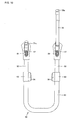
Fig. 4 is a front view of a tension member and a support member; -
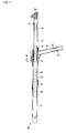
Fig. 5 is a cross-sectional view taken along line V-V inFig. 4 ; -
Fig. 6 is a longitudinal cross-section ofFig. 4 ; -
Fig. 7 is a cross-sectional view taken along line VII-VII inFig. 6 ; -
Fig. 8 is a front view showing a state in which inner pipes are extended upward from the state ofFig. 4 ; -
Fig. 9 is a longitudinal cross-section showing a state in which the inner pipes are extended upward from the state ofFig. 6 ; -
Fig. 10 is a front view showing a state in which a second support bar is extended upward from the state ofFig. 8 ; -
Fig. 11 is a cross-sectional view showing a state in which the inner pipe and the second support bar are extended upward from the state ofFig. 5 ; and -
Fig. 12 is a front view showing a state in which first and second support bars are extended upward from the state ofFig. 8 . -
Figs. 1 through 3 show states in which achild seat 100 according to an embodiment of the present invention is secured to aseat 1 of an automobile by using aseat belt 2 mounted on the automobile. Thechild seat 1 includes abase member 10, aseat body 30, atension member 50, and asupport member 70. Thebase member 10 is fixedly secured to theseat 1 of the automobile by theseat belt 2. Theseat body 30 is rotatably attached to thebase member 10. Thetension member 50 is attached to a front end of thebase member 10. Thesupport member 70 is accommodated in thetension member 50 so as to be movable in an up-down direction. -
Fig. 1 shows a state in which theseat body 10 is attached in a forward facing direction in a chair shape.Fig. 2 shows a state in which theseat body 10 is attached in a sideways direction in a bed shape.Fig. 3 shows a state in which theseat body 10 is attached in a rearward facing direction in a chair shape. - The
base member 10 includes abottom wall portion 11 positioned on a seat portion of theseat 1 of the automobile and a standingwall portion 12 rising upward from a rear end of thebottom wall portion 11. The standingwall portion 12 abuts on a backrest portion of theseat 1 of the automobile. As can be seen especially fromFigs. 2 and3 , thebase member 10 has aclip 13 and anotch 14 in both upper right and upper left sides of the standingwall portion 12. Thebottom wall portion 11 of thebase member 10 includes afront engagement wall 15 at a position close to the front end of thebase member 10 so that theseat belt 2 is wound around thefront engagement wall 15. In order to fix thebase member 11 to theseat 1 of the automobile, theseat belt 1 has the following layout (threading path): theseat belt 2 is threaded through theclip 13 on one side of the standingwall portion 12 and thenotch 14 on the other side thereof and wound around thefront engagement wall 15 of thebottom wall portion 11. - The
seat belt 1 has the same layout regardless of the direction and shape of theseat body 30. It is therefore not necessary to release theseat belt 2 when the direction and/or shape of theseat body 30 are changed and when a child is placed in or taken out of theseat body 30. Moreover, the above belt layout does not hinder a rotation operation of theseat body 30. The rotation operation of theseat belt 30 can be performed with theseat belt 2 attached at a predetermined position. - The
seat body 30 includes aseat portion 31 and abackrest portion 32 rising upward from a rear end of theseat portion 31. Thebackrest portion 32 is reclinable until thechild seat 100 becomes flat like a bed. - The
tension member 50 attached to the front end of thebase member 10 has such a length that thetension member 50 reaches the floor of the automobile, and prevents forward tilting of thebase member 10. In the illustrated embodiment, thetension member 50 has a U-shapedouter pipe 51 and twoinner pipes 52. Theinner pipes 52 are respectively accommodated in longitudinal bar portions of theouter pipe 51 so as to be movable in the up-down direction. A transverse bar portion of theouter pipe 51 is reliably caused to abut on the floor of the automobile by adjusting the extension length of theinner pipes 52. - In the illustrated embodiment, the
support member 70 includes afirst support bar 71 and asecond support bar 72. Thefirst support bar 71 and thesecond support bar 72 are respectively accommodated in theinner pipes 52 so as to be movable in the up-down direction. Aside engagement portion 34 is provided in the outer surface of bothsidewalls 33 of thebackrest portion 32 of theseat body 30. Eachside engagement portion 34 engages with a corresponding one ofhead portions seat body 30 is positioned in the sideways direction in the bed shape. First and secondback engagement portions 35 are provided in the back surface of thebackrest portion 32 of theseat body 30. The first and secondback engagement portions 35 respectively engage with thehead portions seat body 30 is positioned in the rearward facing direction. - When the
seat body 30 is attached to thebase member 10 in the forward facing direction in the chair shape as shown inFig. 1 , the first and second support bars 71, 72 are retracted to a lower position so as to be completely accommodated in the respectiveinner pipes 52. In this state, the back of thebackrest portion 32 of theseat body 30 and the standingwall 12 of thebase member 10 are connected in an upper region by a latch mechanism in order to prevent forward tilting of theseat body 30. A know structure may be used for the latch mechanism. - When the
seat body 30 is attached to thebase member 10 in the sideways direction in the bed shape as shown inFig. 2 , onesupport bar 71 is extended upward from thetension member 50 so that thehead portion 71a at an upper end of thesupport bar 71 is engaged with theside engagement portion 34 formed in onesidewall 33 of thebackrest portion 32 of theseat body 30. This engagement prevents forward tilting of the seat body in the bed shape. When theseat body 30 is positioned in the opposite sideways direction (rotated by 180 degrees), theother support bar 72 is extended upward so that thehead portion 72a at an upper end of thesupport bar 72 is engaged with theside engagement portion 34 of theother sidewall 33. - When the
seat body 30 is attached to thebase member 10 in the rearward facing direction in the chair shape as shown inFig. 3 , the first and second support bars 71, 72 are extended upward from thetension member 50 so that thehead portions back engagement portions 35 formed on the back surface of thebackrest portion 32 of theseat body 30. This engagement prevents forward tilting of theseat body 30 in the rearward facing state. - Hereinafter, a structure of the
tension member 50 and thesupport member 70 will be specifically described with reference toFigs. 4 through 12 . -
Figs. 4 through 7 show a state in which theinner pipes 52 of thetension member 50 are completely accommodated in theouter pipe 51 and thesupport member 70 is retracted to the lower position.Fixed sleeves 53 are respectively attached to upper ends of the pair of longitudinal bar portions of the U-shapedouter pipe 51. Anoperation lever 54 is attached to each fixedsleeve 53. Eachoperation lever 54 has alock pin 55 and is biased by a spring. Each of the pair ofinner pipes 52 accommodated in the longitudinal bar portions of theouter pipe 51 so as to be movable in the up-down direction has a plurality ofholes 56 formed at intervals in the up-down direction. The extension length of theinner pipe 52, that is, the length by which theinner pipe 52 protrudes upward from theouter pipe 52, is fixed when thelock pin 55 engages in thehole 56. -
Figs. 8 and9 show a state in which theouter pipe 51 of thetension member 50 is slid to a lower position in order to reliably make the transverse bar portion of theouter pipe 51 about on the floor of a vehicle. The following operation is performed to transition thetension member 50 from the state ofFigs. 4 and6 to the state ofFigs. 8 and9 : first, the pair of operation levers 54 located at the upper ends of theexternal pipe 51 are pivoted to disengage the lock pins 55 from theholes 56 of theinner pipes 52, respectively. In this state, theouter pipe 51 is slid downward to a predetermined position and the operation levers 54 are released. The pair of operation levers 54 return to an original position by the biasing force of the spring and the pair of lock pins 55 respectively engage inpredetermined holes 56 of theinner pipes 52 to inhibit relative movement between theouter pipe 51 and theinner pipes 52. - An
attachment bracket 57 having aninsertion bar 58 is fixed to an upper end of eachinner pipe 52. Alock pin 59 is attached to eachinsertion bar 58. Eachlock pin 59 is always biased by aplate spring 60 so as to return to a lock position. The pair of insertion bars 58 are respectively received by holes formed in thebase member 11 of thechild seat 100. Although not shown in the figures, the lock pins 59 are respectively engaged in holes formed in thebase member 11, thereby inhibiting movement of the insertion bars 58 in a front-back direction. The insertion bars 58 can be detached from thebase member 11 by disengaging the lock pins 59 from the holes. - In the illustrated embodiment, the
tension member 50 is detachably attached to thebase member 11 of thechild seat 100 through the insertion bars 58. In another embodiment, however, the tension member may be completely fixed to the base member. - The
support member 70 is supported by thetension member 50 so as to be displaceable between upper and lower positions. In the illustrated embodiment, thesupport member 70 has the first and second support bars 71, 72 which are accommodated in the twoinner pipes 52 so as to be movable in the up-down direction. Both support bars have the same structure. The structure of thesecond support bar 72 will now be described with reference toFig. 5 . - The
second support bar 72 has anupper lock pin 73 in its upper part and alower lock pin 75 in its lower part. Theupper lock pin 73 is biased by aplate spring 74 and thelower lock pin 75 is biased by aplate spring 76. Theinner pipe 52 of thetension member 50 has a receivinghole 62 in its upper portion. The receivinghole 62 is engageable with theupper lock pin 73 and thelower lock pin 75. Theattachment bracket 57 fixed to the upper end of theinner pipe 52 has anoperation button 61 at a position facing the receivinghole 62. In the state ofFig. 5 , thesecond support bar 72 is in a lower position and theupper lock pin 73 engages in the receivinghole 62 of theinner pipe 52. -
Figs. 10 and11 show a state in which thesecond support bar 72 is brought to an upper position. The following operation is performed to transition thesecond support bar 72 from the state ofFig. 5 to the state ofFig. 11 : first, theoperation button 61 of theattachment bracket 57 is pressed with a finger to disengage theupper lock pin 73 from the receivinghole 62. Thesecond support bar 72 is then extended upward to engage thehead portion 72a of thesecond support bar 72 with theside engagement portion 34 of theseat body 30. In this state, theoperation button 61 is released, whereby thelower lock pin 75 engages in the receivinghole 62 and the upper position of thesecond support bar 72 is fixed. -
Fig. 12 shows a state in which thefirst support bar 71 and thesecond support bar 72 are both brought to the upper position and fixed. Since an operation to transition the first and second support bars 71, 72 to this state is the same as that described above, description thereof will not be repeated. - Although an embodiment of the present invention has been described above with reference to the figures, the present invention is not limited to the illustrated embodiment. Various modifications and variations can be made to the above illustrated embodiment within the same scope as, or an equivalent scope to, the present invention. Some of such modifications and variations will be described below by way of illustration.
- (1) In the illustrated embodiment, the seat body is switchable among the forward facing state, the rearward facing state, and the sideways facing state having the bed shape on the base member. In another embodiment, the seat body may be switchable between two states, that is, the forward facing state and the sideways facing state having the bed shape.
- (2) In the illustrated embodiment, the seat body is rotatably supported on the base member and the direction of the seat body is changeable. In another embodiment, the seat body may be detachably attached to the base member.
- (3) In the illustrated embodiment, the support member is accommodated in the tension member so as to be displaceable in the up-down direction. In another embodiment, for example, the support member may be attached to an outer surface of the tension member. Alternatively, a foldable or detachable support member may be used instead of the slidable support member.
- (4) The shape of the tension member is not limited to the U shape. The tension member may have a single bar shape.
- The present invention can thus be advantageously used as an automobile child seat.
Claims (11)
- An automobile child seat, comprising:a base member (10) fixedly secured to a seat of an automobile;a seat body (30) attached to said base member and switchable at least between a forward facing state and a sideways facing state in a bed shape;a tension member (50) attached to a front end of said base member and extending to a position where said tension member abuts on a floor of the automobile; anda support member (70) supported by said tension member so as to be displaceable between an upper position and a lower position, whereina side engagement portion (34) is provided in a side surface of said seat body (30), and said side engagement portion (34) engages with said support member (70) when said support member is brought to said upper position in said sideways facing state in the bed shape.
- The automobile child seat according to claim 1, wherein said seat body (30) is switchable to a rearward facing state in addition to said forward facing state and said sideways facing state in the bed shape, a back engagement portion (35) is provided on a back surface of said seat body, and said back engagement portion engages with said support member when said support body is brought to said upper position in said rearward facing state.
- The automobile child seat according to claim 1 or 2, wherein said tension member (50) has a pipe shape, and said support member (70) has a bar shape so that said support member can be received in said pipe-shaped tension member so as to be displaceable in an up-down direction.
- The automobile child seat according to any one of claims 1 to 3, wherein said tension member (50) has a U shape formed by two longitudinal bar portions extending in an up-down direction and spaced apart from each other and a transverse bar portion connecting respective lower ends of the two longitudinal bar portions to each other, and said support member (70) includes first and second support bars (71, 72) respectively supported by said two longitudinal bar portions so as to be displaceable in the up-down direction.
- The automobile child seat according to claim 4, wherein said side engagement portion (34) is provided in both side surfaces of said seat body (30).
- The automobile child seat according to claim 4 or 5, wherein said seat body (30) is switchable to a rearward facing state in addition to said forward facing state and said sideways facing state, first and second back engagement portions (35) are provided on the back surface of said seat body, and said first and second back engagement portions respectively engage with said first and second support bars (71, 72) when said first and second support bars are brought to said upper position in said rearward facing state.
- The automobile child seat according to any one of claims 1 to 6, wherein said seat body (30) is rotatably supported on said base member(10).
- An automobile child seat, comprising:a base member (10) fixedly secured to a seat of an automobile;a seat body (30) attached to said base member and switchable at least between a forward facing state and a rearward facing state;a tension member (50) attached to a front end of said base member and extending to a position where said tension member abuts on a floor of the automobile; anda support member (70) supported by said tension member so as to be displaceable between an upper position and a lower position, whereina back engagement portion (35) is provided on a back surface of said seat body, and said back engagement portion (35) engages with said support member (70) when said support member is brought to said upper position in said rearward facing state.
- The automobile child seat according to claim 8, wherein said tension member (50) has a pipe shape, and said support member (70) has a bar shape so that said support member can be received in said pipe-shaped tension member so as to be displaceable in an up-down direction.
- The automobile child seat according to claim 8 or 9, wherein said tension member (50) has a U shape formed by two longitudinal bar portions extending in an up-down direction and spaced apart from each other and a transverse bar portion connecting respective lower ends of the two longitudinal bar portions to each other, and said support member (70) includes first and second support bars (71, 72) respectively supported by said two longitudinal bar portions so as to be displaceable in the up-down direction.
- An automobile child seat, comprising:a base member (10) fixedly secured to a seat of an automobile;a seat body (30) attached to said base member;a tension member (50) attached to a front end of said base member and extending to a position where said tension member abuts on a floor of the automobile; anda support member (70) supported by said tension member so as to be displaceable between an upper position and a lower position, whereinan engagement portion (34, 35) is provided on said seat body, and said engagement portion engages with said support member when said support member is brought to said upper position.
Applications Claiming Priority (1)
| Application Number | Priority Date | Filing Date | Title |
|---|---|---|---|
| JP2008009166A JP5247161B2 (en) | 2008-01-18 | 2008-01-18 | Child seat for automobile |
Publications (2)
| Publication Number | Publication Date |
|---|---|
| EP2080664A1 true EP2080664A1 (en) | 2009-07-22 |
| EP2080664B1 EP2080664B1 (en) | 2010-07-21 |
Family
ID=40456475
Family Applications (1)
| Application Number | Title | Priority Date | Filing Date |
|---|---|---|---|
| EP09000434A Expired - Fee Related EP2080664B1 (en) | 2008-01-18 | 2009-01-14 | Automobile child seat |
Country Status (5)
| Country | Link |
|---|---|
| US (1) | US7753445B2 (en) |
| EP (1) | EP2080664B1 (en) |
| JP (1) | JP5247161B2 (en) |
| CN (1) | CN101486325B (en) |
| DE (1) | DE602009000062D1 (en) |
Cited By (7)
| Publication number | Priority date | Publication date | Assignee | Title |
|---|---|---|---|---|
| WO2012146761A1 (en) | 2011-04-29 | 2012-11-01 | Dorel France Sa | Self-pivoting child car seat to be fitted to a vehicle seat |
| DE202012007185U1 (en) | 2011-07-28 | 2012-11-30 | Dorel France S.A. | Car seat for firm connection with a seat of a motor vehicle |
| EP2865561A1 (en) * | 2013-10-25 | 2015-04-29 | Britax Child Safety Inc. | Forward and rearward facing child seat with belt tensioning mechanism for improved installation |
| FR3014377A1 (en) * | 2013-12-05 | 2015-06-12 | Dorel France Sa | CAR SEAT WITH A FOLDING FORCE LEG |
| US9187016B2 (en) | 2012-09-04 | 2015-11-17 | Britax Child Safety Inc. | Child seat with belt tensioning mechanism for improved installation |
| US9415647B2 (en) * | 2013-12-10 | 2016-08-16 | Teleswivel, Llc | Adjustable height hitch apparatus |
| WO2018020017A3 (en) * | 2016-07-29 | 2018-04-05 | Cybex Gmbh | Child car seat for attaching to a motor vehicle |
Families Citing this family (34)
| Publication number | Priority date | Publication date | Assignee | Title |
|---|---|---|---|---|
| CN103182966B (en) * | 2008-07-02 | 2015-11-18 | 康贝株式会社 | Child seat |
| AU2016256730B2 (en) * | 2010-02-01 | 2019-01-31 | Hbg Ip Holding Pty Ltd | A Child Restraint for a Vehicle |
| NO336043B1 (en) * | 2010-09-10 | 2015-04-27 | HTS Hans Torgersen & Sønn AS | Rotating child seat for use in a vehicle |
| ES2542741T3 (en) * | 2010-09-14 | 2015-08-11 | Cybex Industrial Ltd. | Child seat |
| JP2012090535A (en) * | 2010-10-25 | 2012-05-17 | Mametora Noki Kk | Mower |
| CN102582479B (en) * | 2011-01-06 | 2014-11-05 | 明门香港股份有限公司 | Supporting device |
| DE202011000229U1 (en) * | 2011-01-31 | 2011-06-09 | Curt Würstl Vermögensverwaltungs-GmbH & Co. KG, 95032 | Baby carrier in the form of a bucket seat |
| EP2701943B1 (en) * | 2011-04-29 | 2015-08-12 | Dorel France SA | Child car seat to be fitted to a vehicle seat |
| DE202012102471U1 (en) | 2012-06-18 | 2012-09-07 | Cybex Gmbh | Child seat for attachment to a motor vehicle seat |
| CN103507675B (en) * | 2012-06-28 | 2016-01-13 | 宝钜儿童用品香港股份有限公司 | Child car seat supporting device and child car safety seat |
| CN103935272B (en) * | 2013-01-18 | 2016-08-17 | 明门香港股份有限公司 | Child safety seat |
| CN203267824U (en) | 2013-05-02 | 2013-11-06 | 中山市隆成日用制品有限公司 | Supporting frame color display mechanism with safety seat pedestal |
| ES1093530Y (en) * | 2013-09-18 | 2014-02-11 | Jane S A (100 0%) | CHILD SEAT FOR CARS |
| KR101399896B1 (en) * | 2013-10-31 | 2014-05-29 | 이명주 | Footrest for carseat |
| US9487111B2 (en) * | 2014-03-24 | 2016-11-08 | Jason Lake | Spinning infant car seat |
| DE202015100327U1 (en) * | 2015-01-23 | 2016-04-26 | Wolfgang Nickel | cradle |
| EP3604029B1 (en) * | 2015-04-28 | 2021-04-14 | Volvo Car Corporation | Support arrangement with child seat |
| US9969305B1 (en) | 2015-11-23 | 2018-05-15 | Dao Sheriff | Swiveling child safety seat |
| WO2017127496A1 (en) * | 2016-01-20 | 2017-07-27 | Dorel Juvenile Group, Inc. | Belt-mount system for juvenile vehicle seat |
| WO2017179745A1 (en) * | 2016-04-12 | 2017-10-19 | (주)동인기연 | Baby car seat allowing position change |
| US10098476B2 (en) * | 2016-04-29 | 2018-10-16 | Wonderland Switzerland Ag | Child high chair |
| US10464450B1 (en) | 2016-09-12 | 2019-11-05 | Steven B. Peterson | Appendage support for child seat |
| CN107554363A (en) * | 2017-07-13 | 2018-01-09 | 宁波宝贝第母婴用品有限公司 | A kind of safety seat and its connection method with car belt |
| EP3498527B1 (en) * | 2017-12-14 | 2021-02-03 | BRITAX RÖMER Kindersicherheit GmbH | Child safety seat |
| US11097639B2 (en) * | 2018-05-24 | 2021-08-24 | Wonderland Switzerland Ag | Support base for a child safety seat |
| US11383623B2 (en) | 2018-07-27 | 2022-07-12 | Safest Seats Llc | Support platform with load leg for child car seat |
| CN109532585A (en) * | 2018-12-20 | 2019-03-29 | 安徽永驰婴童安全科技有限公司 | Detachable support leg device and child safety seat |
| CN113352964A (en) | 2020-03-03 | 2021-09-07 | 宝钜瑞士股份有限公司 | Forward misuse alarm device |
| AU2021201385B1 (en) * | 2021-03-03 | 2022-04-21 | BRITAX RÖMER Kindersicherheit GmbH | A vehicle-mountable child safety seat assembly |
| CN115675204A (en) * | 2021-07-21 | 2023-02-03 | 明门瑞士股份有限公司 | Infant carrier with improved sliding mechanism |
| US12570188B2 (en) | 2022-10-06 | 2026-03-10 | Dorel Juvenile Group, Inc. | Child restraint |
| US12600271B2 (en) * | 2022-10-06 | 2026-04-14 | Dorel Juvenile Group, Inc. | Child restraint |
| US12427896B2 (en) | 2022-10-07 | 2025-09-30 | Dorel Juvenile Group, Inc. | Child restraint |
| TW202444594A (en) * | 2023-03-30 | 2024-11-16 | 瑞士商明門瑞士股份有限公司 | Rotatable child seat with removable booster |
Citations (3)
| Publication number | Priority date | Publication date | Assignee | Title |
|---|---|---|---|---|
| JPH10250426A (en) | 1997-01-08 | 1998-09-22 | Aprica Kassai Inc | Safety seat of the young for automobile |
| JP2003094994A (en) | 2001-09-25 | 2003-04-03 | Combi Corp | Support leg device for child seat |
| WO2007029010A2 (en) * | 2005-09-08 | 2007-03-15 | Britax Excelsior Limited | Child safety seat |
Family Cites Families (16)
| Publication number | Priority date | Publication date | Assignee | Title |
|---|---|---|---|---|
| JPS53109237U (en) * | 1977-02-09 | 1978-09-01 | ||
| US4480870A (en) * | 1981-10-13 | 1984-11-06 | Wimmersperg Heinrich F Von | Infant restraint for vehicles |
| US4640545A (en) * | 1985-05-13 | 1987-02-03 | Wimmersperg Heinrich F Von | Lock for vehicle infant restraint |
| JPS6291730U (en) * | 1985-11-29 | 1987-06-11 | ||
| GB9306977D0 (en) * | 1993-04-03 | 1993-05-26 | Britax Excelsior | Child saftey seat |
| GB9307446D0 (en) * | 1993-04-08 | 1993-06-02 | Britax Excelsior | Child safety seat |
| US5820215A (en) * | 1997-04-29 | 1998-10-13 | Dreisbach; Kurt R. | Child safety seat adapter |
| US6237999B1 (en) * | 1999-08-24 | 2001-05-29 | Donald A. Hobson | Child car seat |
| SE517741C2 (en) * | 2000-11-21 | 2002-07-09 | Lb Invent Ab | Footrest for car seat |
| CA2353111A1 (en) * | 2001-07-13 | 2003-01-13 | Aprica Kassai Kabushikikaisha | Vehicular child safety seat |
| JP3729145B2 (en) * | 2002-03-19 | 2005-12-21 | 日産自動車株式会社 | Child seat support structure of the car body |
| CN2550206Y (en) * | 2002-07-05 | 2003-05-14 | 陈应 | Children safety chair |
| GB0413940D0 (en) * | 2004-06-19 | 2004-07-28 | Britax Excelsior | Child safety seat |
| GB0420414D0 (en) * | 2004-09-14 | 2004-10-20 | Barker Derrick | Child car seat |
| NL1028788C2 (en) * | 2005-04-18 | 2006-10-20 | Maxi Miliaan Bv | Undercarriage as well as child vehicle seat provided with such an undercarriage. |
| EP1970247A1 (en) * | 2007-03-15 | 2008-09-17 | Team-Tex | Device for mounting a child seat in a car and a child seat |
-
2008
- 2008-01-18 JP JP2008009166A patent/JP5247161B2/en not_active Expired - Fee Related
- 2008-12-05 US US12/315,768 patent/US7753445B2/en not_active Expired - Fee Related
-
2009
- 2009-01-14 EP EP09000434A patent/EP2080664B1/en not_active Expired - Fee Related
- 2009-01-14 DE DE602009000062T patent/DE602009000062D1/en active Active
- 2009-01-15 CN CN200910000572.9A patent/CN101486325B/en not_active Expired - Fee Related
Patent Citations (3)
| Publication number | Priority date | Publication date | Assignee | Title |
|---|---|---|---|---|
| JPH10250426A (en) | 1997-01-08 | 1998-09-22 | Aprica Kassai Inc | Safety seat of the young for automobile |
| JP2003094994A (en) | 2001-09-25 | 2003-04-03 | Combi Corp | Support leg device for child seat |
| WO2007029010A2 (en) * | 2005-09-08 | 2007-03-15 | Britax Excelsior Limited | Child safety seat |
Cited By (14)
| Publication number | Priority date | Publication date | Assignee | Title |
|---|---|---|---|---|
| WO2012146761A1 (en) | 2011-04-29 | 2012-11-01 | Dorel France Sa | Self-pivoting child car seat to be fitted to a vehicle seat |
| DE202012007185U1 (en) | 2011-07-28 | 2012-11-30 | Dorel France S.A. | Car seat for firm connection with a seat of a motor vehicle |
| FR2978388A1 (en) * | 2011-07-28 | 2013-02-01 | Dorel France Sa | Car seat for children with different sizes and weights, has control unit controlling installation of seat and permitting and/or prohibiting one of road facing or road opposing positions according to distance between base and head |
| US9187016B2 (en) | 2012-09-04 | 2015-11-17 | Britax Child Safety Inc. | Child seat with belt tensioning mechanism for improved installation |
| EP3527423A1 (en) * | 2013-10-25 | 2019-08-21 | Britax Child Safety Inc. | Forward and rearward facing child seat with belt tensioning mechanism for improved installation |
| EP2865561A1 (en) * | 2013-10-25 | 2015-04-29 | Britax Child Safety Inc. | Forward and rearward facing child seat with belt tensioning mechanism for improved installation |
| US9499074B2 (en) | 2013-10-25 | 2016-11-22 | Britax Child Safety, Inc. | Forward and rearward facing child seat with belt tensioning mechanism for improved installation |
| US9586504B2 (en) | 2013-10-25 | 2017-03-07 | Britax Child Safety, Inc. | Forward and rearward facing child seat with belt tensioning mechanism for improved installation |
| US11117498B2 (en) | 2013-10-25 | 2021-09-14 | Britax Child Safety, Inc. | Forward and rearward facing child seat with belt tensioning mechanism for improved installation |
| US9963051B2 (en) | 2013-10-25 | 2018-05-08 | Britax Child Safety, Inc. | Forward and rearward facing child seat with belt tensioning mechanism for improved installation |
| EP2865561B1 (en) | 2013-10-25 | 2019-01-09 | Britax Child Safety Inc. | Forward and rearward facing child seat with belt tensioning mechanism for improved installation |
| FR3014377A1 (en) * | 2013-12-05 | 2015-06-12 | Dorel France Sa | CAR SEAT WITH A FOLDING FORCE LEG |
| US9415647B2 (en) * | 2013-12-10 | 2016-08-16 | Teleswivel, Llc | Adjustable height hitch apparatus |
| WO2018020017A3 (en) * | 2016-07-29 | 2018-04-05 | Cybex Gmbh | Child car seat for attaching to a motor vehicle |
Also Published As
| Publication number | Publication date |
|---|---|
| CN101486325B (en) | 2013-01-30 |
| JP2009166767A (en) | 2009-07-30 |
| US7753445B2 (en) | 2010-07-13 |
| EP2080664B1 (en) | 2010-07-21 |
| CN101486325A (en) | 2009-07-22 |
| JP5247161B2 (en) | 2013-07-24 |
| DE602009000062D1 (en) | 2010-09-02 |
| US20090184549A1 (en) | 2009-07-23 |
Similar Documents
| Publication | Publication Date | Title |
|---|---|---|
| EP2080664B1 (en) | Automobile child seat | |
| US7681894B2 (en) | Device for fitting seats and the like to the chassis of baby carriages | |
| US7322648B2 (en) | Child seat | |
| US8556344B2 (en) | Child safety seat assembly | |
| CN102371919B (en) | Child seat assembly and base thereof | |
| JP4467732B2 (en) | Child seat base and child seat | |
| US5746478A (en) | Reclining mechanism and latch for child safety seat | |
| US20100207436A1 (en) | Child vehicle seat | |
| JP5076830B2 (en) | Clutch mechanism | |
| EP2241492B1 (en) | A tandem stroller frame with an inclination adjustable second seat | |
| JP2016532601A (en) | Child safety seat | |
| US20030132654A1 (en) | Seat apparatus for automobile | |
| JP2007055433A (en) | Child seat | |
| EP1818239B1 (en) | A device for fitting seats and the like to the chassis of prams | |
| US7419181B2 (en) | Foldable carriage body for carrying a seat | |
| JP5237398B2 (en) | Infant transport device having a plurality of sitting postures | |
| JP5441444B2 (en) | Child seat for vehicle | |
| US20130193731A1 (en) | Vehicle seat | |
| EP2662235B1 (en) | Child vehicle seat and seat and base suitable for such a child vehicle seat | |
| US7165809B2 (en) | Safety seat tether system | |
| JP2009018760A (en) | Vehicle seat | |
| JP2008290580A (en) | Child seat | |
| JP4982103B2 (en) | Child seat forming member | |
| JP2007283780A (en) | Child seat forming member for automobile | |
| JP4946038B2 (en) | child seat |
Legal Events
| Date | Code | Title | Description |
|---|---|---|---|
| PUAI | Public reference made under article 153(3) epc to a published international application that has entered the european phase |
Free format text: ORIGINAL CODE: 0009012 |
|
| AK | Designated contracting states |
Kind code of ref document: A1 Designated state(s): AT BE BG CH CY CZ DE DK EE ES FI FR GB GR HR HU IE IS IT LI LT LU LV MC MK MT NL NO PL PT RO SE SI SK TR |
|
| AX | Request for extension of the european patent |
Extension state: AL BA RS |
|
| RAP1 | Party data changed (applicant data changed or rights of an application transferred) |
Owner name: APRICA CHILDREN'S PRODUCTS INC. |
|
| 17P | Request for examination filed |
Effective date: 20091008 |
|
| GRAP | Despatch of communication of intention to grant a patent |
Free format text: ORIGINAL CODE: EPIDOSNIGR1 |
|
| AKX | Designation fees paid |
Designated state(s): DE FR GB |
|
| GRAS | Grant fee paid |
Free format text: ORIGINAL CODE: EPIDOSNIGR3 |
|
| GRAA | (expected) grant |
Free format text: ORIGINAL CODE: 0009210 |
|
| AK | Designated contracting states |
Kind code of ref document: B1 Designated state(s): DE FR GB |
|
| REG | Reference to a national code |
Ref country code: GB Ref legal event code: FG4D |
|
| REF | Corresponds to: |
Ref document number: 602009000062 Country of ref document: DE Date of ref document: 20100902 Kind code of ref document: P |
|
| PLBE | No opposition filed within time limit |
Free format text: ORIGINAL CODE: 0009261 |
|
| STAA | Information on the status of an ep patent application or granted ep patent |
Free format text: STATUS: NO OPPOSITION FILED WITHIN TIME LIMIT |
|
| 26N | No opposition filed |
Effective date: 20110426 |
|
| REG | Reference to a national code |
Ref country code: DE Ref legal event code: R097 Ref document number: 602009000062 Country of ref document: DE Effective date: 20110426 |
|
| PGFP | Annual fee paid to national office [announced via postgrant information from national office to epo] |
Ref country code: DE Payment date: 20130129 Year of fee payment: 5 Ref country code: GB Payment date: 20130125 Year of fee payment: 5 Ref country code: FR Payment date: 20130211 Year of fee payment: 5 |
|
| REG | Reference to a national code |
Ref country code: DE Ref legal event code: R119 Ref document number: 602009000062 Country of ref document: DE |
|
| GBPC | Gb: european patent ceased through non-payment of renewal fee |
Effective date: 20140114 |
|
| REG | Reference to a national code |
Ref country code: DE Ref legal event code: R119 Ref document number: 602009000062 Country of ref document: DE Effective date: 20140801 |
|
| PG25 | Lapsed in a contracting state [announced via postgrant information from national office to epo] |
Ref country code: DE Free format text: LAPSE BECAUSE OF NON-PAYMENT OF DUE FEES Effective date: 20140801 |
|
| REG | Reference to a national code |
Ref country code: FR Ref legal event code: ST Effective date: 20140930 |
|
| PG25 | Lapsed in a contracting state [announced via postgrant information from national office to epo] |
Ref country code: FR Free format text: LAPSE BECAUSE OF NON-PAYMENT OF DUE FEES Effective date: 20140131 Ref country code: GB Free format text: LAPSE BECAUSE OF NON-PAYMENT OF DUE FEES Effective date: 20140114 |