EP2083200A1 - Seal assembly - Google Patents
Seal assembly Download PDFInfo
- Publication number
- EP2083200A1 EP2083200A1 EP08001351A EP08001351A EP2083200A1 EP 2083200 A1 EP2083200 A1 EP 2083200A1 EP 08001351 A EP08001351 A EP 08001351A EP 08001351 A EP08001351 A EP 08001351A EP 2083200 A1 EP2083200 A1 EP 2083200A1
- Authority
- EP
- European Patent Office
- Prior art keywords
- openings
- seal assembly
- rotor
- stator
- chambers
- Prior art date
- Legal status (The legal status is an assumption and is not a legal conclusion. Google has not performed a legal analysis and makes no representation as to the accuracy of the status listed.)
- Withdrawn
Links
- 238000013016 damping Methods 0.000 claims description 5
- 239000000463 material Substances 0.000 claims description 3
- 210000003027 ear inner Anatomy 0.000 description 15
- 239000012530 fluid Substances 0.000 description 9
- 230000000368 destabilizing effect Effects 0.000 description 6
- 230000000694 effects Effects 0.000 description 2
- 238000007789 sealing Methods 0.000 description 2
- 230000005284 excitation Effects 0.000 description 1
- 238000009434 installation Methods 0.000 description 1
- 238000000034 method Methods 0.000 description 1
Images

Classifications
-
- F—MECHANICAL ENGINEERING; LIGHTING; HEATING; WEAPONS; BLASTING
- F16—ENGINEERING ELEMENTS AND UNITS; GENERAL MEASURES FOR PRODUCING AND MAINTAINING EFFECTIVE FUNCTIONING OF MACHINES OR INSTALLATIONS; THERMAL INSULATION IN GENERAL
- F16J—PISTONS; CYLINDERS; SEALINGS
- F16J15/00—Sealings
- F16J15/44—Free-space packings
-
- F—MECHANICAL ENGINEERING; LIGHTING; HEATING; WEAPONS; BLASTING
- F01—MACHINES OR ENGINES IN GENERAL; ENGINE PLANTS IN GENERAL; STEAM ENGINES
- F01D—NON-POSITIVE DISPLACEMENT MACHINES OR ENGINES, e.g. STEAM TURBINES
- F01D11/00—Preventing or minimising internal leakage of working-fluid, e.g. between stages
- F01D11/02—Preventing or minimising internal leakage of working-fluid, e.g. between stages by non-contact sealings, e.g. of labyrinth type
- F01D11/025—Seal clearance control; Floating assembly; Adaptation means to differential thermal dilatations
-
- F—MECHANICAL ENGINEERING; LIGHTING; HEATING; WEAPONS; BLASTING
- F01—MACHINES OR ENGINES IN GENERAL; ENGINE PLANTS IN GENERAL; STEAM ENGINES
- F01D—NON-POSITIVE DISPLACEMENT MACHINES OR ENGINES, e.g. STEAM TURBINES
- F01D11/00—Preventing or minimising internal leakage of working-fluid, e.g. between stages
- F01D11/02—Preventing or minimising internal leakage of working-fluid, e.g. between stages by non-contact sealings, e.g. of labyrinth type
- F01D11/04—Preventing or minimising internal leakage of working-fluid, e.g. between stages by non-contact sealings, e.g. of labyrinth type using sealing fluid, e.g. steam
-
- F—MECHANICAL ENGINEERING; LIGHTING; HEATING; WEAPONS; BLASTING
- F16—ENGINEERING ELEMENTS AND UNITS; GENERAL MEASURES FOR PRODUCING AND MAINTAINING EFFECTIVE FUNCTIONING OF MACHINES OR INSTALLATIONS; THERMAL INSULATION IN GENERAL
- F16J—PISTONS; CYLINDERS; SEALINGS
- F16J15/00—Sealings
- F16J15/44—Free-space packings
- F16J15/441—Free-space packings with floating ring
- F16J15/442—Free-space packings with floating ring segmented
Definitions
- This invention relates to a seal assembly between a rotor and a stator especially of a turbo-machinery with a close clearance gap there between according to the introductory part of claim 1.
- Labyrinth seals generate large magnitude, destabilizing forces on turbo-machinery rotors especially when operating in high density fluids.
- labyrinth configurations have been developed in an attempt to reduce the destabilizing forcing function and at the same time increase the damping properties.
- Honeycomb style seals are an example in this context. These have been quite successfully applied in high pressure, centrifugal compressors especially in gas reinjection applications.
- Honeycomb style labyrinths have however a very high direct stiffness and are sensitive to actual rotor position and running gap geometry. This has led to several incidents in the industry where corrective actions were required to bring units within specifications.
- Rotation of the high density gas inside the labyrinth is a root cause for the large magnitude, destabilizing forces inside labyrinth seals. These forces have a pronounced effect on the design of high density turbo-machinery: they limit the maximum possible running speed, the maximum number of impellers at the rotor, the maximum process pressure, the minimum diameter of the rotor shaft, and the efficiency or a combination of these.
- the object of the present invention is to reduce the destabilizing forces acting on the rotor of rotating turbo-machinery.
- one or more annular chamber(s) between the stator and rotor are created that have multiple openings towards the fluid side. Through the openings the chamber is in contact with the close clearance gap, i.e. the fluid side.
- the inventive seal assembly is therefore capable to reduce the flow induced excitation forces inside the close clearance gap.
- a rotor 1 is pivoted in a stator 2.
- the rotor 1 and the stator 2 belong to a rotating turbo-machinery for example a compressor, a steam turbine, a gas turbine, an expander, an electric motor, or a pump.
- a close clearance gap 3 is present between a rotor surface of the rotor 1 and a stator surface 4 of the stator 2.
- the surfaces surrounding the clearance gap 3 basically can have any geometry ranging from single diameter, staggered, conical, etc.
- the rotor surface or the stator surface 4 or both surfaces are provided with openings 5 which open into at least one chamber 6 arranged at that side of the openings 5 turned away from the clearance gap 3.
- a perforated plate 7 having openings 5 is fastened to the stator 2.
- webs 8 or ribs are provided in circumferential direction.
- the webs 8 surround annular chambers 6 which inner width is greater than the inner width of the openings 5 and into which a series of openings 5 opens.
- the various annular chambers 6 can be axially interconnected through holes 9 in the webs 8 of the perforated plate 7, thus forming one large annular chamber.
- the close clearance gap 3 is filled with a fluid which is the result of the rotating rotor surface and the stationary stator surface 4 that are in close proximity to each other.
- a fluid which is the result of the rotating rotor surface and the stationary stator surface 4 that are in close proximity to each other.
- the annular chambers 6 are in contact with the close clearance gap 3 and the fluid therein. Because of a leakage of fluid through the openings 5 there is annular pressure equalizing.
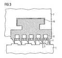
- the labyrinth seal shown in Fig. 3 consists of a labyrinth holder 10 that has several labyrinth teeth 11.
- the labyrinth holder 10 is arranged in the stator 2.
- the labyrinth teeth 11 face the surface of the rotor 1 defining a small clearance 3.
- the rotor surface basically can have any geometry ranging from single diameter, staggered, conical, etc.
- a perforated section 12 having perforations or openings 5 is present between each labyrinth tooth 11 .
- the openings 5 are typically arranged more or less perpendicular to the sealing surface and can have special geometry optimizing the dynamical behaviour of the labyrinth.
- the chambers 6 may be filled with damping material.
Landscapes
- Engineering & Computer Science (AREA)
- General Engineering & Computer Science (AREA)
- Mechanical Engineering (AREA)
- Structures Of Non-Positive Displacement Pumps (AREA)
- Turbine Rotor Nozzle Sealing (AREA)
- Sealing Using Fluids, Sealing Without Contact, And Removal Of Oil (AREA)
Abstract
Seal assembly between a rotor (1) and a stator (2) especially of a turbo-machinery is provided with a close clearance gap (3) there between. The clearance gap (3) is bordered by a rotor surface at the side of the rotor (1) and by a stator surface (4) at the side of the stator (2). The rotor surface or the stator surface (4) or both are provided with openings (5) which open into at least one chamber (6) arranged at that side of the openings (5) turned away from the clearance gap (3).
Description
- This invention relates to a seal assembly between a rotor and a stator especially of a turbo-machinery with a close clearance gap there between according to the introductory part of claim 1.
- A type of close clearance gap that is often applied in turbo-machinery is the labyrinth seal. Labyrinth seals generate large magnitude, destabilizing forces on turbo-machinery rotors especially when operating in high density fluids. Over the years several alternative labyrinth configurations have been developed in an attempt to reduce the destabilizing forcing function and at the same time increase the damping properties. Honeycomb style seals are an example in this context. These have been quite successfully applied in high pressure, centrifugal compressors especially in gas reinjection applications. Honeycomb style labyrinths have however a very high direct stiffness and are sensitive to actual rotor position and running gap geometry. This has led to several incidents in the industry where corrective actions were required to bring units within specifications.
- Rotation of the high density gas inside the labyrinth is a root cause for the large magnitude, destabilizing forces inside labyrinth seals. These forces have a pronounced effect on the design of high density turbo-machinery: they limit the maximum possible running speed, the maximum number of impellers at the rotor, the maximum process pressure, the minimum diameter of the rotor shaft, and the efficiency or a combination of these.
- Besides labyrinth seals the destabilizing forces can occur in any close clearance gap where a fluid fills the gap between stator part and rotor part.
- The object of the present invention is to reduce the destabilizing forces acting on the rotor of rotating turbo-machinery.
- Starting from a seal assembly according to the introductory part of claim 1 the object is achieved by the features of the characterizing part of claim 1. Advantageous embodiments of the invention are described in the subclaims
- Through the invention one or more annular chamber(s) between the stator and rotor are created that have multiple openings towards the fluid side. Through the openings the chamber is in contact with the close clearance gap, i.e. the fluid side.
- The chambers with these openings have the following characteristics:
- They minimise circumferential swirling of the fluid thereby minimizing the destabilizing forces. This is accomplished through pressure equalisation in angular direction inside the chamber(s). Through the openings the pressure inside the fluid gap will also be equalized by flow leakage through the openings.
- They act as an dynamic damper of dynamics pressure fluctuations through the special combination of the openings and the pressure equalizing chambers. This damping effect can be further enhanced by installation of special damping material in the pressure equalizing chamber.
- The inventive seal assembly is therefore capable to reduce the flow induced excitation forces inside the close clearance gap.
- The invention will be described by way of example with reference to the accompanying drawing in which:
-
Fig. 1 is a longitudinal section of a seal assembly with a close clearance gap; -
Fig. 2 is a partial sectional view along line II - II ofFig. 1 and -
Fig. 3 is a longitudinal section through a labyrinth seal. - A rotor 1 is pivoted in a
stator 2. The rotor 1 and thestator 2 belong to a rotating turbo-machinery for example a compressor, a steam turbine, a gas turbine, an expander, an electric motor, or a pump. For sealing aclose clearance gap 3 is present between a rotor surface of the rotor 1 and astator surface 4 of thestator 2. The surfaces surrounding theclearance gap 3 basically can have any geometry ranging from single diameter, staggered, conical, etc. - The rotor surface or the
stator surface 4 or both surfaces are provided withopenings 5 which open into at least onechamber 6 arranged at that side of theopenings 5 turned away from theclearance gap 3. As shown more clearly inFig. 1 and 2 aperforated plate 7 havingopenings 5 is fastened to thestator 2. At the back side of theperforated plate 7, that is the side turned away from theclearance gap 3,webs 8 or ribs are provided in circumferential direction. Thewebs 8 surroundannular chambers 6 which inner width is greater than the inner width of theopenings 5 and into which a series ofopenings 5 opens. The variousannular chambers 6 can be axially interconnected throughholes 9 in thewebs 8 of theperforated plate 7, thus forming one large annular chamber. - The
close clearance gap 3 is filled with a fluid which is the result of the rotating rotor surface and thestationary stator surface 4 that are in close proximity to each other. Through theopenings 5 theannular chambers 6 are in contact with theclose clearance gap 3 and the fluid therein. Because of a leakage of fluid through theopenings 5 there is annular pressure equalizing. - The labyrinth seal shown in
Fig. 3 consists of alabyrinth holder 10 that hasseveral labyrinth teeth 11. Thelabyrinth holder 10 is arranged in thestator 2. Thelabyrinth teeth 11 face the surface of the rotor 1 defining asmall clearance 3. The rotor surface basically can have any geometry ranging from single diameter, staggered, conical, etc. - Between each labyrinth tooth 11 a perforated
section 12 having perforations oropenings 5 is present creatingpressure equalizing chambers 6 at the backside of this perforatedsection 12. Theopenings 5 are typically arranged more or less perpendicular to the sealing surface and can have special geometry optimizing the dynamical behaviour of the labyrinth. Thechambers 6 may be filled with damping material.
Claims (8)
- Seal assembly between a rotor (1) and a stator (2) especially of a turbo-machinery with a close clearance gap (3) there between which clearance gap (3) is bordered by a rotor surface at the side of the rotor (1) and by a stator surface (4) at the side of the stator (2), characterized in that the rotor surface or the stator surface (4) or both are provided with openings (5) which open into at least one chamber (6) arranged at that side of the openings (5) turned away from the clearance gap (3).
- Seal assembly as claimed in claim 1, characterized in that the inner width of the chambers (6) is larger than the inner width of the openings (5).
- Seal assembly as claimed in claim 1 or 2, characterized by one or more annular chambers (6) extending in circumferential direction, into which or into each of them a plurality of openings (5) open.
- Seal assembly as claimed in claim 3, characterized in that the annular chambers (6) are axially interconnected by holes (9).
- Seal assembly as claimed in claim 3, characterized in that the openings (5) are perforations of a perforated plate (7) fastened to the stator surface (4) and that the chambers (6) are arranged at the back side of the perforated plate (7).
- Seal assembly as claimed in claim 1, characterized in that the axes of the openings (5) are basically perpendicular to the axis of the rotor (1) to be sealed.
- Seal assembly as claimed in claims 1, characterized in that the chambers (6) are filled with damping material.
- Seal assembly comprising labyrinth teeth (11) with chambers (6) in between as claimed in claim 1, characterized in that a perforated section (12) having openings (5) is installed between the labyrinth teeth (11) and the chambers (6).
Priority Applications (7)
| Application Number | Priority Date | Filing Date | Title |
|---|---|---|---|
| EP08001351A EP2083200A1 (en) | 2008-01-24 | 2008-01-24 | Seal assembly |
| AT09704015T ATE522755T1 (en) | 2008-01-24 | 2009-01-23 | SEAL ARRANGEMENT |
| ES09704015T ES2371530T3 (en) | 2008-01-24 | 2009-01-23 | HERMETIC BOARD ASSEMBLY. |
| CN200980102971.4A CN101925766B (en) | 2008-01-24 | 2009-01-23 | Seal assembly |
| US12/863,838 US8915705B2 (en) | 2008-01-24 | 2009-01-23 | Seal assembly |
| PCT/EP2009/050783 WO2009092797A1 (en) | 2008-01-24 | 2009-01-23 | Seal assembly |
| EP09704015A EP2232110B1 (en) | 2008-01-24 | 2009-01-23 | Seal assembly |
Applications Claiming Priority (1)
| Application Number | Priority Date | Filing Date | Title |
|---|---|---|---|
| EP08001351A EP2083200A1 (en) | 2008-01-24 | 2008-01-24 | Seal assembly |
Publications (1)
| Publication Number | Publication Date |
|---|---|
| EP2083200A1 true EP2083200A1 (en) | 2009-07-29 |
Family
ID=39511063
Family Applications (2)
| Application Number | Title | Priority Date | Filing Date |
|---|---|---|---|
| EP08001351A Withdrawn EP2083200A1 (en) | 2008-01-24 | 2008-01-24 | Seal assembly |
| EP09704015A Not-in-force EP2232110B1 (en) | 2008-01-24 | 2009-01-23 | Seal assembly |
Family Applications After (1)
| Application Number | Title | Priority Date | Filing Date |
|---|---|---|---|
| EP09704015A Not-in-force EP2232110B1 (en) | 2008-01-24 | 2009-01-23 | Seal assembly |
Country Status (6)
| Country | Link |
|---|---|
| US (1) | US8915705B2 (en) |
| EP (2) | EP2083200A1 (en) |
| CN (1) | CN101925766B (en) |
| AT (1) | ATE522755T1 (en) |
| ES (1) | ES2371530T3 (en) |
| WO (1) | WO2009092797A1 (en) |
Cited By (6)
| Publication number | Priority date | Publication date | Assignee | Title |
|---|---|---|---|---|
| WO2013058112A1 (en) * | 2011-10-21 | 2013-04-25 | 三菱重工業株式会社 | Seal device |
| WO2014087512A1 (en) * | 2012-12-06 | 2014-06-12 | 三菱重工コンプレッサ株式会社 | Sealing device and rotating machine |
| JP2015166636A (en) * | 2015-07-01 | 2015-09-24 | 三菱重工業株式会社 | Seal device |
| EP2453111A3 (en) * | 2010-11-12 | 2015-12-16 | Mitsubishi Hitachi Power Systems, Ltd. | Labyrinth seals for turbomachinery |
| ITUB20153472A1 (en) * | 2015-09-08 | 2017-03-08 | Nuovo Pignone Tecnologie Srl | TURBOMACCHINA WITH A BALANCING DRUM LAYER AND COMPASS, AND METHOD |
| EP3271621B1 (en) * | 2015-03-18 | 2020-12-30 | Hammelmann GmbH | Sealing device |
Families Citing this family (14)
| Publication number | Priority date | Publication date | Assignee | Title |
|---|---|---|---|---|
| WO2012129475A2 (en) | 2011-03-24 | 2012-09-27 | Dresser-Rand Company | Interlocking hole pattern seal |
| ITCO20120019A1 (en) | 2012-04-27 | 2013-10-28 | Nuovo Pignone Srl | LABYRINTH HIGHLY DAMPENED SEALS WITH HELICOIDAL AND CYLINDRICAL-MIXED SHAPE |
| JP2014020509A (en) * | 2012-07-20 | 2014-02-03 | Toshiba Corp | Seal device, axial flow turbine, and power-generating plant |
| WO2014038079A1 (en) * | 2012-09-10 | 2014-03-13 | 株式会社 日立製作所 | Turbo machine |
| US9200528B2 (en) * | 2012-09-11 | 2015-12-01 | General Electric Company | Swirl interruption seal teeth for seal assembly |
| WO2014077058A1 (en) * | 2012-11-13 | 2014-05-22 | 三菱重工コンプレッサ株式会社 | Rotary machine |
| DE102015104994A1 (en) * | 2015-03-31 | 2016-10-06 | Areva Gmbh | Sealing arrangement for a rotatably mounted component of a rotary machine |
| CN109488391B (en) * | 2017-10-25 | 2024-05-07 | 智伟电力(无锡)有限公司 | A vortex steam seal for a steam turbine |
| KR102088969B1 (en) * | 2018-10-23 | 2020-03-16 | 진영티비엑스(주) | Labyrinth seal assembly |
| US11686390B2 (en) * | 2018-12-21 | 2023-06-27 | Acd, Llc | Turboexpander labyrinth seal |
| JP7349248B2 (en) * | 2019-03-08 | 2023-09-22 | 三菱重工業株式会社 | Rotating machinery and seal rings |
| CN113863994A (en) * | 2021-10-12 | 2021-12-31 | 华能(大连)热电有限责任公司 | A steam sealer with high sealing performance and its assembling method |
| CN115325167A (en) * | 2022-08-19 | 2022-11-11 | 北京化工大学 | Novel low-leakage high-vibration-damping sealing structure |
| US12241588B2 (en) * | 2023-05-09 | 2025-03-04 | Saudi Arabian Oil Company | Systems and methods of mitigating lubricant leakage from seal assemblies |
Citations (5)
| Publication number | Priority date | Publication date | Assignee | Title |
|---|---|---|---|---|
| DE211478C (en) * | ||||
| CH407168A (en) * | 1961-11-08 | 1966-02-15 | Licentia Gmbh | Non-contact shaft seal for turbo machinery |
| US3614112A (en) * | 1969-02-14 | 1971-10-19 | Gen Electric | Fluid deflector apparatus |
| DE2143736A1 (en) * | 1971-09-01 | 1973-03-08 | Erno Raumfahrttechnik Gmbh | ARRANGEMENT FOR SEALING SHAFT PIPES |
| US4350345A (en) * | 1981-04-01 | 1982-09-21 | General Electric Company | Air-sealed oil deflector |
Family Cites Families (5)
| Publication number | Priority date | Publication date | Assignee | Title |
|---|---|---|---|---|
| US2908515A (en) * | 1955-08-09 | 1959-10-13 | Belton A Copp | Shaft seal |
| GB1224234A (en) * | 1968-07-19 | 1971-03-03 | English Electric Co Ltd | Turbines |
| US5161943A (en) * | 1991-03-11 | 1992-11-10 | Dresser-Rand Company, A General Partnership | Swirl control labyrinth seal |
| US5190440A (en) * | 1991-03-11 | 1993-03-02 | Dresser-Rand Company | Swirl control labyrinth seal |
| JP2002285802A (en) * | 2001-03-26 | 2002-10-03 | Toshiba Corp | Labyrinth sealing device for rotating machinery |
-
2008
- 2008-01-24 EP EP08001351A patent/EP2083200A1/en not_active Withdrawn
-
2009
- 2009-01-23 AT AT09704015T patent/ATE522755T1/en not_active IP Right Cessation
- 2009-01-23 WO PCT/EP2009/050783 patent/WO2009092797A1/en not_active Ceased
- 2009-01-23 EP EP09704015A patent/EP2232110B1/en not_active Not-in-force
- 2009-01-23 CN CN200980102971.4A patent/CN101925766B/en not_active Expired - Fee Related
- 2009-01-23 ES ES09704015T patent/ES2371530T3/en active Active
- 2009-01-23 US US12/863,838 patent/US8915705B2/en not_active Expired - Fee Related
Patent Citations (5)
| Publication number | Priority date | Publication date | Assignee | Title |
|---|---|---|---|---|
| DE211478C (en) * | ||||
| CH407168A (en) * | 1961-11-08 | 1966-02-15 | Licentia Gmbh | Non-contact shaft seal for turbo machinery |
| US3614112A (en) * | 1969-02-14 | 1971-10-19 | Gen Electric | Fluid deflector apparatus |
| DE2143736A1 (en) * | 1971-09-01 | 1973-03-08 | Erno Raumfahrttechnik Gmbh | ARRANGEMENT FOR SEALING SHAFT PIPES |
| US4350345A (en) * | 1981-04-01 | 1982-09-21 | General Electric Company | Air-sealed oil deflector |
Cited By (12)
| Publication number | Priority date | Publication date | Assignee | Title |
|---|---|---|---|---|
| EP2453111A3 (en) * | 2010-11-12 | 2015-12-16 | Mitsubishi Hitachi Power Systems, Ltd. | Labyrinth seals for turbomachinery |
| WO2013058112A1 (en) * | 2011-10-21 | 2013-04-25 | 三菱重工業株式会社 | Seal device |
| JP2013087935A (en) * | 2011-10-21 | 2013-05-13 | Mitsubishi Heavy Ind Ltd | Seal device |
| WO2014087512A1 (en) * | 2012-12-06 | 2014-06-12 | 三菱重工コンプレッサ株式会社 | Sealing device and rotating machine |
| JPWO2014087512A1 (en) * | 2012-12-06 | 2017-01-05 | 三菱重工コンプレッサ株式会社 | Sealing device and rotating machine |
| EP3271621B1 (en) * | 2015-03-18 | 2020-12-30 | Hammelmann GmbH | Sealing device |
| JP2015166636A (en) * | 2015-07-01 | 2015-09-24 | 三菱重工業株式会社 | Seal device |
| ITUB20153472A1 (en) * | 2015-09-08 | 2017-03-08 | Nuovo Pignone Tecnologie Srl | TURBOMACCHINA WITH A BALANCING DRUM LAYER AND COMPASS, AND METHOD |
| WO2017042200A1 (en) * | 2015-09-08 | 2017-03-16 | Nuovo Pignone Tecnologie Srl | Turbomachine with a balance drum and sleeve arrangement and method |
| US20180266428A1 (en) * | 2015-09-08 | 2018-09-20 | Nuovo Pignone Tecnologie Srl | Turbomachine with a balance drum and sleeve arrangement and method |
| AU2016318917B2 (en) * | 2015-09-08 | 2020-07-02 | Nuovo Pignone Tecnologie Srl | Turbomachine with a balance drum and sleeve arrangement and method |
| US10816006B2 (en) | 2015-09-08 | 2020-10-27 | Nuovo Pignone Srl | Turbomachine with a balance drum and sleeve arrangement and method |
Also Published As
| Publication number | Publication date |
|---|---|
| US8915705B2 (en) | 2014-12-23 |
| WO2009092797A1 (en) | 2009-07-30 |
| ATE522755T1 (en) | 2011-09-15 |
| US20110020114A1 (en) | 2011-01-27 |
| EP2232110B1 (en) | 2011-08-31 |
| CN101925766B (en) | 2012-11-28 |
| EP2232110A1 (en) | 2010-09-29 |
| ES2371530T3 (en) | 2012-01-04 |
| CN101925766A (en) | 2010-12-22 |
Similar Documents
| Publication | Publication Date | Title |
|---|---|---|
| EP2083200A1 (en) | Seal assembly | |
| US6715766B2 (en) | Steam feed hole for retractable packing segments in rotary machines | |
| CN104471293B (en) | Highly damping labyrinth seals with helical form or mixed helical-cylindrical form | |
| JP5227114B2 (en) | Labyrinth compression seal and turbine incorporating it | |
| CN101622458B (en) | Seal device for rotary fluid machine and rotary fluid machine | |
| EP2318738B1 (en) | Leaf seal | |
| US9909440B2 (en) | Interlocking hole pattern seal | |
| EP2453111A2 (en) | Labyrinth seals for turbomachinery | |
| US7731476B2 (en) | Method and device for reducing axial thrust and radial oscillations and rotary machines using same | |
| KR101950924B1 (en) | complex sealing apparatus for turbine | |
| EP3190267B1 (en) | Structure for multi-stage sealing of turbine | |
| EP2532838B1 (en) | A compliant plate seal assembly for a turbo machine | |
| US20110052375A1 (en) | Bearing system for rotor in rotating machines | |
| US20070069477A1 (en) | Stepped labyrinth damper seal | |
| RU2608664C2 (en) | Honeycomb gland and method of its making | |
| EP2959114A1 (en) | Riffled seal for a turbomachine, turbomachine and method of manufacturing a riffled seal for a turbomachine | |
| US20160290511A1 (en) | Shaft seal and method for producing same | |
| KR101914776B1 (en) | hybrid sealing apparatus for turbine | |
| CN115163213B (en) | A rotating power generation device with an isolation steam seal structure | |
| Pugachev et al. | Performance analysis of hybrid brush pocket damper seals using computational fluid dynamics | |
| JP2026508921A (en) | Sealing segment for turbomachinery | |
| RU167797U1 (en) | Labyrinth seal | |
| WO2021121994A1 (en) | Contra-rotating turbine and method |
Legal Events
| Date | Code | Title | Description |
|---|---|---|---|
| PUAI | Public reference made under article 153(3) epc to a published international application that has entered the european phase |
Free format text: ORIGINAL CODE: 0009012 |
|
| AK | Designated contracting states |
Kind code of ref document: A1 Designated state(s): AT BE BG CH CY CZ DE DK EE ES FI FR GB GR HR HU IE IS IT LI LT LU LV MC MT NL NO PL PT RO SE SI SK TR |
|
| AX | Request for extension of the european patent |
Extension state: AL BA MK RS |
|
| AKX | Designation fees paid | ||
| REG | Reference to a national code |
Ref country code: DE Ref legal event code: 8566 |
|
| STAA | Information on the status of an ep patent application or granted ep patent |
Free format text: STATUS: THE APPLICATION IS DEEMED TO BE WITHDRAWN |
|
| 18D | Application deemed to be withdrawn |
Effective date: 20100130 |