EP2086028A1 - A clip - Google Patents
A clip Download PDFInfo
- Publication number
- EP2086028A1 EP2086028A1 EP08250365A EP08250365A EP2086028A1 EP 2086028 A1 EP2086028 A1 EP 2086028A1 EP 08250365 A EP08250365 A EP 08250365A EP 08250365 A EP08250365 A EP 08250365A EP 2086028 A1 EP2086028 A1 EP 2086028A1
- Authority
- EP
- European Patent Office
- Prior art keywords
- clip
- ring
- shaped sections
- members
- sleeve
- Prior art date
- Legal status (The legal status is an assumption and is not a legal conclusion. Google has not performed a legal analysis and makes no representation as to the accuracy of the status listed.)
- Granted
Links
- 238000006073 displacement reaction Methods 0.000 claims abstract description 10
- 229910000639 Spring steel Inorganic materials 0.000 claims description 3
- 239000000463 material Substances 0.000 claims description 3
- 239000012858 resilient material Substances 0.000 claims description 2
- 238000000926 separation method Methods 0.000 claims description 2
- 238000007789 sealing Methods 0.000 description 6
- 239000000446 fuel Substances 0.000 description 4
- 229910045601 alloy Inorganic materials 0.000 description 1
- 239000000956 alloy Substances 0.000 description 1
- 230000006835 compression Effects 0.000 description 1
- 238000007906 compression Methods 0.000 description 1
- 239000000356 contaminant Substances 0.000 description 1
- 230000001419 dependent effect Effects 0.000 description 1
- 238000009434 installation Methods 0.000 description 1
- 239000002184 metal Substances 0.000 description 1
- 238000012986 modification Methods 0.000 description 1
- 230000004048 modification Effects 0.000 description 1
- 229920000642 polymer Polymers 0.000 description 1
- 230000001681 protective effect Effects 0.000 description 1
Images



Classifications
-
- F—MECHANICAL ENGINEERING; LIGHTING; HEATING; WEAPONS; BLASTING
- F16—ENGINEERING ELEMENTS AND UNITS; GENERAL MEASURES FOR PRODUCING AND MAINTAINING EFFECTIVE FUNCTIONING OF MACHINES OR INSTALLATIONS; THERMAL INSULATION IN GENERAL
- F16B—DEVICES FOR FASTENING OR SECURING CONSTRUCTIONAL ELEMENTS OR MACHINE PARTS TOGETHER, e.g. NAILS, BOLTS, CIRCLIPS, CLAMPS, CLIPS OR WEDGES; JOINTS OR JOINTING
- F16B2/00—Friction-grip releasable fastenings
- F16B2/20—Clips, i.e. with gripping action effected solely by the inherent resistance to deformation of the material of the fastening
- F16B2/22—Clips, i.e. with gripping action effected solely by the inherent resistance to deformation of the material of the fastening of resilient material, e.g. rubbery material
- F16B2/24—Clips, i.e. with gripping action effected solely by the inherent resistance to deformation of the material of the fastening of resilient material, e.g. rubbery material of metal
- F16B2/241—Clips, i.e. with gripping action effected solely by the inherent resistance to deformation of the material of the fastening of resilient material, e.g. rubbery material of metal of sheet metal
- F16B2/245—Clips, i.e. with gripping action effected solely by the inherent resistance to deformation of the material of the fastening of resilient material, e.g. rubbery material of metal of sheet metal external, i.e. with contracting action
-
- H—ELECTRICITY
- H10—SEMICONDUCTOR DEVICES; ELECTRIC SOLID-STATE DEVICES NOT OTHERWISE PROVIDED FOR
- H10N—ELECTRIC SOLID-STATE DEVICES NOT OTHERWISE PROVIDED FOR
- H10N30/00—Piezoelectric or electrostrictive devices
- H10N30/80—Constructional details
- H10N30/88—Mounts; Supports; Enclosures; Casings
-
- Y—GENERAL TAGGING OF NEW TECHNOLOGICAL DEVELOPMENTS; GENERAL TAGGING OF CROSS-SECTIONAL TECHNOLOGIES SPANNING OVER SEVERAL SECTIONS OF THE IPC; TECHNICAL SUBJECTS COVERED BY FORMER USPC CROSS-REFERENCE ART COLLECTIONS [XRACs] AND DIGESTS
- Y10—TECHNICAL SUBJECTS COVERED BY FORMER USPC
- Y10T—TECHNICAL SUBJECTS COVERED BY FORMER US CLASSIFICATION
- Y10T24/00—Buckles, buttons, clasps, etc.
- Y10T24/44—Clasp, clip, support-clamp, or required component thereof
Definitions
- the present invention relates to a clip for sealing the ends of a sleeve located around a piezo-electric actuator to the body of that piezo-electric actuator.
- a piezo-electric actuator may be located in an accumulator volume which receives high pressure fuel. It is essential to prevent contact between the fuel and the actuator to prevent the actuator from suffering damage. To prevent such damage it is known to provide a sleeve 2 around the actuator 1. This sleeve 2 must be sealed to the actuator 1 at each end to prevent the ingress of fuel and any contaminants that it may contain.
- the present invention provides a clip for securing a sleeve to the body of a piezo-electric actuator in an actuator assembly, the clip taking the form of a band comprising first and second axially spaced ring-like members joined by a plurality of inwardly facing substantially arch shaped sections, the arch shaped sections defining the minimum inner diameter of the band, whereby axial displacement of the ring-like members way from one another causes flexing of the arch shaped sections to increase the minimum inner diameter of the band while axial displacement of the ring-like members towards one another causes flexing of the arch shaped sections to reduce the minimum inner diameter of the band.
- the band is circular.
- the arch shaped sections are evenly circumferentially spaced between the ring-like members.
- the ring-like members and the arch shaped sections may be integrally formed from a single material, the arch shaped sections being defined by cut-out regions, apertures or slots extending between the ring-like members and between adjacent arch shaped sections.
- the clip is made from a resilient material.
- Spring steel is considered a particularly suitable material for the clip.
- each of the ring-like members may be provided with engagement means for engagement with a tool to permit displacement of the ring-like members away from each other.
- the engagement means may comprise radially extending projections for engagement by corresponding projections provided on a suitable tool in the manner of a bayonet fastening.
- the radially extending projections extend inwardly from the inner surface of each ring-like member.
- an actuator assembly comprising a clip as claimed in any preceding claim, an actuator and a sleeve, which overlaps at least part of the body of the actuator, wherein at the location where the sleeve overlaps the body of the actuator the minimum separation of the external walls of the sleeve is greater than the minimum diameter of the clip, when the clip is in an unstressed state, such that when the clip is fitted over the sleeve the clip applies a clamping force to the sleeve in order to create a seal between the sleeve and the body of the actuator.
- a clip for securing a sleeve to the body of a piezo-electric actuator in an actuator assembly is in the form of a single piece band 10 made from spring steel, the band defining first and second axially spaced continuous circular rings 12,14 joined by a plurality of circumferentially inwardly facing substantially arch shaped sections 16, the rings 12,14 defining the outer diameter of the clip and the arch shaped sections 16 defining the minimum inner diameter of the band 10.
- axial displacement of the rings 12,14 away from one another causes flexing of the arch shaped sections 16 to increase the minimum inner diameter of the band 10, while axial displacement of the rings 12,14 towards one another causes flexing of the arch shaped sections 16 to reduce the minimum inner diameter of the band.
- the arch shaped sections 16 of the band 10 are defined by axially extending slots 18 extending between the rings 12,14 and between adjacent arch shaped sections 16.
- radially inwardly facing projections 20 are formed around the outermost edge of each side of the band 10 at evenly spaced locations around the circumference of each ring 12,14.
- a protective strip 25 is wrapped around the region of the sleeve to be clamping such that the strip 25 lies beneath the clip, in use. This avoids any risk of pinching of the sleeve due to the gaps 18 between the arch shaped sections 16.
- the strip 25 may be formed from a metal, polymer or rubber selected to transmit the load for the clip onto the sleeve therebeneath.
- the two rings 12,14 of the band 10 are gripped by a suitable tool and pulled apart to reduce the minimum diameter of the band 10 to allow the band to be readily slid over the sleeve and end of the actuator over which the end of the sleeve is located.
- the rings are released and the resilience of the arch shaped sections pulls the rings 12,14 back together and causes the minimum inner diameter of the band 10 to constrict to providing a radial clamping force around the end of the sleeve to seal the sleeve over the end of the actuator.
- FIG. 5 to 7 An example of a suitable tool is shown in Figs. 5 to 7 .
- One of the rings 12,14 of the band 10 is gripped between two half rings 40 each having an inwardly facing lip 42 extending into the space between the rings 12,14.
- a second part of the tool comprises a cylinder 44 with radially extending teeth 46 than are dimensioned to engage into the clip between the inwardly facing projections 20 of one side of the clip and be locked in place behind the projections 20 by rotation of the inserted cylinder, whereby the inner diameter of the clip can be expanded by pulling the cylinder 44 away from the half rings 40 to pull the two rings 12,14 of the band 10 apart.
- an axial loading can be placed on the band 10 to urge the rings 12,14 of the band towards one another.
- the clip according to the present invention has been described in relation to the sealing of a sleeve over the end of a piezo-electric actuator, it is envisaged that the clip may be used wherever a radial clamping or sealing force is required, for example as a hose clip, pipe connection, or a cable joint.
Landscapes
- Engineering & Computer Science (AREA)
- General Engineering & Computer Science (AREA)
- Mechanical Engineering (AREA)
- Clamps And Clips (AREA)
- Fuel-Injection Apparatus (AREA)
- General Electrical Machinery Utilizing Piezoelectricity, Electrostriction Or Magnetostriction (AREA)
Abstract
Description
- The present invention relates to a clip for sealing the ends of a sleeve located around a piezo-electric actuator to the body of that piezo-electric actuator.
- In a fuel injector a piezo-electric actuator may be located in an accumulator volume which receives high pressure fuel. It is essential to prevent contact between the fuel and the actuator to prevent the actuator from suffering damage. To prevent such damage it is known to provide a
sleeve 2 around the actuator 1. Thissleeve 2 must be sealed to the actuator 1 at each end to prevent the ingress of fuel and any contaminants that it may contain. - It is known to provide a
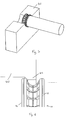
metallic sealing ring 3 around the end of thesleeve 2 to seal the end of the actuator 1. Such an arrangement is shown inFig. 1 . However, such known arrangement is expensive and difficult to install and is very temperature dependent, relying on the use of expensive alloys to avoid differential thermal expansion between the actuator and the sealing ring. - According to a first aspect, the present invention provides a clip for securing a sleeve to the body of a piezo-electric actuator in an actuator assembly, the clip taking the form of a band comprising first and second axially spaced ring-like members joined by a plurality of inwardly facing substantially arch shaped sections, the arch shaped sections defining the minimum inner diameter of the band, whereby axial displacement of the ring-like members way from one another causes flexing of the arch shaped sections to increase the minimum inner diameter of the band while axial displacement of the ring-like members towards one another causes flexing of the arch shaped sections to reduce the minimum inner diameter of the band.
- Preferably the band is circular. In a preferred embodiment the arch shaped sections are evenly circumferentially spaced between the ring-like members.
- The ring-like members and the arch shaped sections may be integrally formed from a single material, the arch shaped sections being defined by cut-out regions, apertures or slots extending between the ring-like members and between adjacent arch shaped sections.
- Preferably the clip is made from a resilient material. Spring steel is considered a particularly suitable material for the clip.
- To enable the use of a tool to displace the ring-like members during installation of the clip, each of the ring-like members may be provided with engagement means for engagement with a tool to permit displacement of the ring-like members away from each other. The engagement means may comprise radially extending projections for engagement by corresponding projections provided on a suitable tool in the manner of a bayonet fastening. Preferably the radially extending projections extend inwardly from the inner surface of each ring-like member.
- According to a further aspect if the present invention, there is provided an actuator assembly comprising a clip as claimed in any preceding claim, an actuator and a sleeve, which overlaps at least part of the body of the actuator, wherein at the location where the sleeve overlaps the body of the actuator the minimum separation of the external walls of the sleeve is greater than the minimum diameter of the clip, when the clip is in an unstressed state, such that when the clip is fitted over the sleeve the clip applies a clamping force to the sleeve in order to create a seal between the sleeve and the body of the actuator.
- Embodiments of the invention will now be described, by way of example only, with reference to the accompanying drawings, in which:-
-
Fig. 2 is a perspective view of a clip according to a first embodiment of the present invention; -
Fig. 3a is a side view of the clip ofFig. 2 showing movement of the ring under axial compression; -
Fig. 3b is a side view of the clip ofFig. 2 showing movement of the ring under axial expansion; -
Fig. 4 is a perspective view of a clip according to a second embodiment of the present invention; and -
Fig. 5 is a perspective view of the clip ofFig. 2 showing a tool to enable fitting of the clip over a sleeve; -
Fig. 6 is a detailed view of part of one part of the tool ofFig. 5 ; and -
Fig. 7 is a detailed view of a second part of the tool ofFig. 5 . - As illustrated in
Fig. 2 , a clip for securing a sleeve to the body of a piezo-electric actuator in an actuator assembly is in the form of asingle piece band 10 made from spring steel, the band defining first and second axially spaced continuouscircular rings shaped sections 16, therings shaped sections 16 defining the minimum inner diameter of theband 10. - As illustrated in
Fig. 3 , axial displacement of therings shaped sections 16 to increase the minimum inner diameter of theband 10, while axial displacement of therings sections 16 to reduce the minimum inner diameter of the band. - The arch
shaped sections 16 of theband 10 are defined by axially extendingslots 18 extending between therings shaped sections 16. - To allow a tool to grip each ring of the band to pull the rings away from each other to reduce the inner diameter of the clip to enable fitting over the sleeve, or other article to be clamped or sealed, radially inwardly facing
projections 20 are formed around the outermost edge of each side of theband 10 at evenly spaced locations around the circumference of eachring - In an alternative embodiment of the present invention, illustrated in
Fig. 4 , a protective strip 25 is wrapped around the region of the sleeve to be clamping such that the strip 25 lies beneath the clip, in use. This avoids any risk of pinching of the sleeve due to thegaps 18 between the archshaped sections 16. The strip 25 may be formed from a metal, polymer or rubber selected to transmit the load for the clip onto the sleeve therebeneath. - In use, the two
rings band 10 are gripped by a suitable tool and pulled apart to reduce the minimum diameter of theband 10 to allow the band to be readily slid over the sleeve and end of the actuator over which the end of the sleeve is located. Once in position, the rings are released and the resilience of the arch shaped sections pulls therings band 10 to constrict to providing a radial clamping force around the end of the sleeve to seal the sleeve over the end of the actuator. - An example of a suitable tool is shown in
Figs. 5 to 7 . One of therings band 10 is gripped between twohalf rings 40 each having an inwardly facinglip 42 extending into the space between therings cylinder 44 with radially extendingteeth 46 than are dimensioned to engage into the clip between the inwardly facingprojections 20 of one side of the clip and be locked in place behind theprojections 20 by rotation of the inserted cylinder, whereby the inner diameter of the clip can be expanded by pulling thecylinder 44 away from thehalf rings 40 to pull the tworings band 10 apart. - If a greater sealing force is required, an axial loading can be placed on the
band 10 to urge therings - While the clip according to the present invention has been described in relation to the sealing of a sleeve over the end of a piezo-electric actuator, it is envisaged that the clip may be used wherever a radial clamping or sealing force is required, for example as a hose clip, pipe connection, or a cable joint.
- Various modifications and variations to the described embodiments of the invention will be apparent to those skilled in the art without departing from the scope of the invention as defined in the appended claims. Although the invention has been described in connection with specific preferred embodiments, it should be understood that the invention as claimed should not be unduly limited to such specific embodiments.
Claims (10)
- A clip for securing a sleeve to the body of a piezo-electric actuator in an actuator assembly, the clip taking the form of a band (10) comprising first and second axially spaced ring-like members (12,14) joined by a plurality of inwardly facing substantially arch shaped sections (16), the arch shaped sections (16) defining the minimum inner diameter of the band (10), whereby axial displacement of the ring-like members (12,14) way from one another causes flexing of the arch shaped sections (16) to increase the minimum inner diameter of the band (10) while axial displacement of the ring-like members (12,14) towards one another causes flexing of the arch shaped sections (16) to reduce the minimum inner diameter of the band (10).
- A clip as claimed in claim 1, wherein the band is (10) circular.
- A clip as claimed in claim 2, wherein the arch shaped sections (16) are evenly circumferentially spaced between the ring-like members (12,14).
- A clip as claimed in any preceding claim, wherein the ring-like members (12,14) and the arch shaped sections (16) are integrally formed from a single material, the arch shaped sections (16) being defined by cut-out regions, apertures or slots (18) extending between the ring-like members (12,14) and between adjacent arch shaped sections (16).
- A clip as claimed in any preceding claim made from a resilient material.
- A clip as claimed in claim 5 made from spring steel.
- A clip as claimed in any preceding claim, wherein each of the ring-like members (12,14) is provided with engagement means for engagement with a tool to permit displacement of the ring-like members away from each other.
- A clip as claimed in claim 7, wherein the engagement means comprise radially extending projections (20) for engagement by corresponding projections provided on a suitable tool in the manner of a bayonet fastening.
- A clip as claimed in claim 8, wherein the radially extending projections (20) extend inwardly from the inner surface of each ring-like member.
- An actuator assembly comprising a clip as claimed in any preceding claim, an actuator and a sleeve, which overlaps at least part of the body of the actuator, wherein at the location where the sleeve overlaps the body of the actuator the minimum separation of the external walls of the sleeve is greater than the minimum diameter of the clip, when the clip is in an unstressed state, such that when the clip is fitted over the sleeve the clip applies a clamping force to the sleeve in order to create a seal between the sleeve and the body of the actuator.
Priority Applications (4)
| Application Number | Priority Date | Filing Date | Title |
|---|---|---|---|
| AT08250365T ATE525756T1 (en) | 2008-01-30 | 2008-01-30 | CLAMP |
| EP08250365A EP2086028B1 (en) | 2008-01-30 | 2008-01-30 | A clip |
| JP2009016387A JP5128510B2 (en) | 2008-01-30 | 2009-01-28 | clip |
| US12/362,600 US7948146B2 (en) | 2008-01-30 | 2009-01-30 | Clip |
Applications Claiming Priority (1)
| Application Number | Priority Date | Filing Date | Title |
|---|---|---|---|
| EP08250365A EP2086028B1 (en) | 2008-01-30 | 2008-01-30 | A clip |
Publications (2)
| Publication Number | Publication Date |
|---|---|
| EP2086028A1 true EP2086028A1 (en) | 2009-08-05 |
| EP2086028B1 EP2086028B1 (en) | 2011-09-21 |
Family
ID=39661626
Family Applications (1)
| Application Number | Title | Priority Date | Filing Date |
|---|---|---|---|
| EP08250365A Not-in-force EP2086028B1 (en) | 2008-01-30 | 2008-01-30 | A clip |
Country Status (4)
| Country | Link |
|---|---|
| US (1) | US7948146B2 (en) |
| EP (1) | EP2086028B1 (en) |
| JP (1) | JP5128510B2 (en) |
| AT (1) | ATE525756T1 (en) |
Cited By (1)
| Publication number | Priority date | Publication date | Assignee | Title |
|---|---|---|---|---|
| EP2343746A1 (en) | 2010-01-11 | 2011-07-13 | Delphi Technologies Holding S.à.r.l. | Method of Encapsulating an Actuator having a Piezoelectric Actuator Stack |
Citations (4)
| Publication number | Priority date | Publication date | Assignee | Title |
|---|---|---|---|---|
| DE102005024710A1 (en) | 2005-05-30 | 2006-12-07 | Robert Bosch Gmbh | Fuel injector |
| EP1783842A1 (en) * | 2005-11-04 | 2007-05-09 | Delphi Technologies, Inc. | Actuator arrangement |
| DE102006026932A1 (en) | 2006-06-09 | 2007-12-13 | Siemens Ag | Piezo-actuator for use as part of injector for common rail diesel fuel injection system, has air gap between outer side of spring and inner wall of housing, and punched and/or curved sheet metal heat guiding plate arranged in air gap |
| EP1978242A1 (en) | 2007-04-05 | 2008-10-08 | Delphi Technologies, Inc. | A clip |
Family Cites Families (10)
| Publication number | Priority date | Publication date | Assignee | Title |
|---|---|---|---|---|
| JPS5276721A (en) * | 1975-12-22 | 1977-06-28 | Toyota Motor Corp | Hose-clip |
| DE3740237C2 (en) * | 1987-11-27 | 1996-06-05 | Fichtel & Sachs Ag | Wire ring for snap connection |
| JPH0610615U (en) * | 1992-07-17 | 1994-02-10 | 日本ケーブル・システム株式会社 | Spring clip for control cable |
| JPH0710533U (en) * | 1993-07-26 | 1995-02-14 | 日産ディーゼル工業株式会社 | Snap ring for shaft locking |
| JP2000087936A (en) * | 1998-09-09 | 2000-03-28 | Haruto Morimoto | Snap ring |
| JP2000087935A (en) * | 1998-09-11 | 2000-03-28 | Ochiai:Kk | Grip ring |
| US6038119A (en) * | 1998-09-21 | 2000-03-14 | Atkins; Ian Paul | Overvoltage protection device including wafer of varistor material |
| JP2004156711A (en) * | 2002-11-06 | 2004-06-03 | Ochiai:Kk | Ring clip |
| JP5031824B2 (en) * | 2006-05-03 | 2012-09-26 | デルファイ・テクノロジーズ・ホールディング・エス.アー.エール.エル. | Method for coating an actuator |
| GB0711557D0 (en) * | 2007-06-15 | 2007-07-25 | Delphi Tech Inc | A collapsible clip |
-
2008
- 2008-01-30 AT AT08250365T patent/ATE525756T1/en not_active IP Right Cessation
- 2008-01-30 EP EP08250365A patent/EP2086028B1/en not_active Not-in-force
-
2009
- 2009-01-28 JP JP2009016387A patent/JP5128510B2/en not_active Expired - Fee Related
- 2009-01-30 US US12/362,600 patent/US7948146B2/en not_active Expired - Fee Related
Patent Citations (4)
| Publication number | Priority date | Publication date | Assignee | Title |
|---|---|---|---|---|
| DE102005024710A1 (en) | 2005-05-30 | 2006-12-07 | Robert Bosch Gmbh | Fuel injector |
| EP1783842A1 (en) * | 2005-11-04 | 2007-05-09 | Delphi Technologies, Inc. | Actuator arrangement |
| DE102006026932A1 (en) | 2006-06-09 | 2007-12-13 | Siemens Ag | Piezo-actuator for use as part of injector for common rail diesel fuel injection system, has air gap between outer side of spring and inner wall of housing, and punched and/or curved sheet metal heat guiding plate arranged in air gap |
| EP1978242A1 (en) | 2007-04-05 | 2008-10-08 | Delphi Technologies, Inc. | A clip |
Cited By (2)
| Publication number | Priority date | Publication date | Assignee | Title |
|---|---|---|---|---|
| EP2343746A1 (en) | 2010-01-11 | 2011-07-13 | Delphi Technologies Holding S.à.r.l. | Method of Encapsulating an Actuator having a Piezoelectric Actuator Stack |
| WO2011082843A1 (en) | 2010-01-11 | 2011-07-14 | Delphi Technologies Holding S.A.R.L. | Method of encapsulating an actuator having a piezoelectric actuator stack |
Also Published As
| Publication number | Publication date |
|---|---|
| US7948146B2 (en) | 2011-05-24 |
| EP2086028B1 (en) | 2011-09-21 |
| JP5128510B2 (en) | 2013-01-23 |
| JP2009243680A (en) | 2009-10-22 |
| ATE525756T1 (en) | 2011-10-15 |
| US20090206701A1 (en) | 2009-08-20 |
Similar Documents
| Publication | Publication Date | Title |
|---|---|---|
| US12129941B2 (en) | Coupling having arcuate stiffness ribs | |
| EP2932145B1 (en) | Jointed bridge for clamp assembly | |
| EP3159583B1 (en) | Mechanical seal | |
| AU2010257209B2 (en) | A tube coupling | |
| JP2687954B2 (en) | Fixing device for the hose part pushed into the pipe part | |
| EP2494249B1 (en) | Pipe coupling with seal pressing device | |
| JP6800791B2 (en) | Hose clamp with flat spring liner | |
| JPH05256383A (en) | Pipe fitting | |
| EP2737239B1 (en) | Clamp assembly with resilient band having notches | |
| GB2105425A (en) | Hose coupling | |
| US20090189357A1 (en) | Shaft seal having integrated removal feature | |
| US20100264652A1 (en) | Hose-line connector and line assembly | |
| EP1338840B1 (en) | Fuel hose, fuel hose connection method and fuel hose connection structure | |
| JP2020507042A (en) | Clamp | |
| KR20140078703A (en) | Hose clamp | |
| EP2086028B1 (en) | A clip | |
| US20060249915A1 (en) | Shaft seal having integrated removal feature | |
| JP4061554B2 (en) | Connector hose connection structure | |
| JP2012172752A (en) | Hose fastening structure | |
| HK1167701A1 (en) | Connection device for a plastic tube | |
| HK1212419B (en) | Coupling having arcuate stiffness ribs | |
| HK1167701B (en) | Connection device for a plastic tube | |
| JP2008202767A (en) | Piping connection structure |
Legal Events
| Date | Code | Title | Description |
|---|---|---|---|
| PUAI | Public reference made under article 153(3) epc to a published international application that has entered the european phase |
Free format text: ORIGINAL CODE: 0009012 |
|
| 17P | Request for examination filed |
Effective date: 20090116 |
|
| AK | Designated contracting states |
Kind code of ref document: A1 Designated state(s): AT BE BG CH CY CZ DE DK EE ES FI FR GB GR HR HU IE IS IT LI LT LU LV MC MT NL NO PL PT RO SE SI SK TR |
|
| AX | Request for extension of the european patent |
Extension state: AL BA MK RS |
|
| 17Q | First examination report despatched |
Effective date: 20091008 |
|
| RAP1 | Party data changed (applicant data changed or rights of an application transferred) |
Owner name: DELPHI TECHNOLOGIES HOLDING S.A.R.L. |
|
| AKX | Designation fees paid |
Designated state(s): AT BE BG CH CY CZ DE DK EE ES FI FR GB GR HR HU IE IS IT LI LT LU LV MC MT NL NO PL PT RO SE SI SK TR |
|
| GRAP | Despatch of communication of intention to grant a patent |
Free format text: ORIGINAL CODE: EPIDOSNIGR1 |
|
| GRAS | Grant fee paid |
Free format text: ORIGINAL CODE: EPIDOSNIGR3 |
|
| GRAA | (expected) grant |
Free format text: ORIGINAL CODE: 0009210 |
|
| AK | Designated contracting states |
Kind code of ref document: B1 Designated state(s): AT BE BG CH CY CZ DE DK EE ES FI FR GB GR HR HU IE IS IT LI LT LU LV MC MT NL NO PL PT RO SE SI SK TR |
|
| REG | Reference to a national code |
Ref country code: GB Ref legal event code: FG4D |
|
| REG | Reference to a national code |
Ref country code: CH Ref legal event code: EP |
|
| REG | Reference to a national code |
Ref country code: IE Ref legal event code: FG4D |
|
| REG | Reference to a national code |
Ref country code: DE Ref legal event code: R096 Ref document number: 602008009949 Country of ref document: DE Effective date: 20111201 |
|
| REG | Reference to a national code |
Ref country code: NL Ref legal event code: VDEP Effective date: 20110921 |
|
| PG25 | Lapsed in a contracting state [announced via postgrant information from national office to epo] |
Ref country code: NO Free format text: LAPSE BECAUSE OF FAILURE TO SUBMIT A TRANSLATION OF THE DESCRIPTION OR TO PAY THE FEE WITHIN THE PRESCRIBED TIME-LIMIT Effective date: 20111221 Ref country code: HR Free format text: LAPSE BECAUSE OF FAILURE TO SUBMIT A TRANSLATION OF THE DESCRIPTION OR TO PAY THE FEE WITHIN THE PRESCRIBED TIME-LIMIT Effective date: 20110921 Ref country code: LT Free format text: LAPSE BECAUSE OF FAILURE TO SUBMIT A TRANSLATION OF THE DESCRIPTION OR TO PAY THE FEE WITHIN THE PRESCRIBED TIME-LIMIT Effective date: 20110921 Ref country code: FI Free format text: LAPSE BECAUSE OF FAILURE TO SUBMIT A TRANSLATION OF THE DESCRIPTION OR TO PAY THE FEE WITHIN THE PRESCRIBED TIME-LIMIT Effective date: 20110921 Ref country code: SE Free format text: LAPSE BECAUSE OF FAILURE TO SUBMIT A TRANSLATION OF THE DESCRIPTION OR TO PAY THE FEE WITHIN THE PRESCRIBED TIME-LIMIT Effective date: 20110921 |
|
| LTIE | Lt: invalidation of european patent or patent extension |
Effective date: 20110921 |
|
| PG25 | Lapsed in a contracting state [announced via postgrant information from national office to epo] |
Ref country code: CY Free format text: LAPSE BECAUSE OF FAILURE TO SUBMIT A TRANSLATION OF THE DESCRIPTION OR TO PAY THE FEE WITHIN THE PRESCRIBED TIME-LIMIT Effective date: 20110921 Ref country code: AT Free format text: LAPSE BECAUSE OF FAILURE TO SUBMIT A TRANSLATION OF THE DESCRIPTION OR TO PAY THE FEE WITHIN THE PRESCRIBED TIME-LIMIT Effective date: 20110921 Ref country code: LV Free format text: LAPSE BECAUSE OF FAILURE TO SUBMIT A TRANSLATION OF THE DESCRIPTION OR TO PAY THE FEE WITHIN THE PRESCRIBED TIME-LIMIT Effective date: 20110921 Ref country code: SI Free format text: LAPSE BECAUSE OF FAILURE TO SUBMIT A TRANSLATION OF THE DESCRIPTION OR TO PAY THE FEE WITHIN THE PRESCRIBED TIME-LIMIT Effective date: 20110921 Ref country code: GR Free format text: LAPSE BECAUSE OF FAILURE TO SUBMIT A TRANSLATION OF THE DESCRIPTION OR TO PAY THE FEE WITHIN THE PRESCRIBED TIME-LIMIT Effective date: 20111222 |
|
| REG | Reference to a national code |
Ref country code: AT Ref legal event code: MK05 Ref document number: 525756 Country of ref document: AT Kind code of ref document: T Effective date: 20110921 |
|
| PG25 | Lapsed in a contracting state [announced via postgrant information from national office to epo] |
Ref country code: BE Free format text: LAPSE BECAUSE OF FAILURE TO SUBMIT A TRANSLATION OF THE DESCRIPTION OR TO PAY THE FEE WITHIN THE PRESCRIBED TIME-LIMIT Effective date: 20110921 |
|
| PG25 | Lapsed in a contracting state [announced via postgrant information from national office to epo] |
Ref country code: CZ Free format text: LAPSE BECAUSE OF FAILURE TO SUBMIT A TRANSLATION OF THE DESCRIPTION OR TO PAY THE FEE WITHIN THE PRESCRIBED TIME-LIMIT Effective date: 20110921 Ref country code: IS Free format text: LAPSE BECAUSE OF FAILURE TO SUBMIT A TRANSLATION OF THE DESCRIPTION OR TO PAY THE FEE WITHIN THE PRESCRIBED TIME-LIMIT Effective date: 20120121 Ref country code: SK Free format text: LAPSE BECAUSE OF FAILURE TO SUBMIT A TRANSLATION OF THE DESCRIPTION OR TO PAY THE FEE WITHIN THE PRESCRIBED TIME-LIMIT Effective date: 20110921 |
|
| PG25 | Lapsed in a contracting state [announced via postgrant information from national office to epo] |
Ref country code: NL Free format text: LAPSE BECAUSE OF FAILURE TO SUBMIT A TRANSLATION OF THE DESCRIPTION OR TO PAY THE FEE WITHIN THE PRESCRIBED TIME-LIMIT Effective date: 20110921 Ref country code: PT Free format text: LAPSE BECAUSE OF FAILURE TO SUBMIT A TRANSLATION OF THE DESCRIPTION OR TO PAY THE FEE WITHIN THE PRESCRIBED TIME-LIMIT Effective date: 20120123 Ref country code: PL Free format text: LAPSE BECAUSE OF FAILURE TO SUBMIT A TRANSLATION OF THE DESCRIPTION OR TO PAY THE FEE WITHIN THE PRESCRIBED TIME-LIMIT Effective date: 20110921 Ref country code: RO Free format text: LAPSE BECAUSE OF FAILURE TO SUBMIT A TRANSLATION OF THE DESCRIPTION OR TO PAY THE FEE WITHIN THE PRESCRIBED TIME-LIMIT Effective date: 20110921 Ref country code: EE Free format text: LAPSE BECAUSE OF FAILURE TO SUBMIT A TRANSLATION OF THE DESCRIPTION OR TO PAY THE FEE WITHIN THE PRESCRIBED TIME-LIMIT Effective date: 20110921 Ref country code: IT Free format text: LAPSE BECAUSE OF FAILURE TO SUBMIT A TRANSLATION OF THE DESCRIPTION OR TO PAY THE FEE WITHIN THE PRESCRIBED TIME-LIMIT Effective date: 20110921 |
|
| PLBE | No opposition filed within time limit |
Free format text: ORIGINAL CODE: 0009261 |
|
| STAA | Information on the status of an ep patent application or granted ep patent |
Free format text: STATUS: NO OPPOSITION FILED WITHIN TIME LIMIT |
|
| PG25 | Lapsed in a contracting state [announced via postgrant information from national office to epo] |
Ref country code: DK Free format text: LAPSE BECAUSE OF FAILURE TO SUBMIT A TRANSLATION OF THE DESCRIPTION OR TO PAY THE FEE WITHIN THE PRESCRIBED TIME-LIMIT Effective date: 20110921 |
|
| 26N | No opposition filed |
Effective date: 20120622 |
|
| PG25 | Lapsed in a contracting state [announced via postgrant information from national office to epo] |
Ref country code: MC Free format text: LAPSE BECAUSE OF NON-PAYMENT OF DUE FEES Effective date: 20120131 |
|
| REG | Reference to a national code |
Ref country code: CH Ref legal event code: PL |
|
| GBPC | Gb: european patent ceased through non-payment of renewal fee |
Effective date: 20120130 |
|
| REG | Reference to a national code |
Ref country code: DE Ref legal event code: R097 Ref document number: 602008009949 Country of ref document: DE Effective date: 20120622 |
|
| REG | Reference to a national code |
Ref country code: IE Ref legal event code: MM4A |
|
| PG25 | Lapsed in a contracting state [announced via postgrant information from national office to epo] |
Ref country code: LI Free format text: LAPSE BECAUSE OF NON-PAYMENT OF DUE FEES Effective date: 20120131 Ref country code: CH Free format text: LAPSE BECAUSE OF NON-PAYMENT OF DUE FEES Effective date: 20120131 Ref country code: GB Free format text: LAPSE BECAUSE OF NON-PAYMENT OF DUE FEES Effective date: 20120130 |
|
| PG25 | Lapsed in a contracting state [announced via postgrant information from national office to epo] |
Ref country code: IE Free format text: LAPSE BECAUSE OF NON-PAYMENT OF DUE FEES Effective date: 20120130 |
|
| PG25 | Lapsed in a contracting state [announced via postgrant information from national office to epo] |
Ref country code: BG Free format text: LAPSE BECAUSE OF FAILURE TO SUBMIT A TRANSLATION OF THE DESCRIPTION OR TO PAY THE FEE WITHIN THE PRESCRIBED TIME-LIMIT Effective date: 20111221 |
|
| PG25 | Lapsed in a contracting state [announced via postgrant information from national office to epo] |
Ref country code: MT Free format text: LAPSE BECAUSE OF FAILURE TO SUBMIT A TRANSLATION OF THE DESCRIPTION OR TO PAY THE FEE WITHIN THE PRESCRIBED TIME-LIMIT Effective date: 20110921 |
|
| PG25 | Lapsed in a contracting state [announced via postgrant information from national office to epo] |
Ref country code: ES Free format text: LAPSE BECAUSE OF FAILURE TO SUBMIT A TRANSLATION OF THE DESCRIPTION OR TO PAY THE FEE WITHIN THE PRESCRIBED TIME-LIMIT Effective date: 20120101 |
|
| PG25 | Lapsed in a contracting state [announced via postgrant information from national office to epo] |
Ref country code: TR Free format text: LAPSE BECAUSE OF FAILURE TO SUBMIT A TRANSLATION OF THE DESCRIPTION OR TO PAY THE FEE WITHIN THE PRESCRIBED TIME-LIMIT Effective date: 20110921 |
|
| PG25 | Lapsed in a contracting state [announced via postgrant information from national office to epo] |
Ref country code: LU Free format text: LAPSE BECAUSE OF NON-PAYMENT OF DUE FEES Effective date: 20120130 |
|
| REG | Reference to a national code |
Ref country code: FR Ref legal event code: TP Owner name: DELPHI INTERNATIONAL OPERATIONS LUXEMBOURG S.A, LU Effective date: 20140516 |
|
| PG25 | Lapsed in a contracting state [announced via postgrant information from national office to epo] |
Ref country code: HU Free format text: LAPSE BECAUSE OF FAILURE TO SUBMIT A TRANSLATION OF THE DESCRIPTION OR TO PAY THE FEE WITHIN THE PRESCRIBED TIME-LIMIT Effective date: 20080130 |
|
| REG | Reference to a national code |
Ref country code: DE Ref legal event code: R081 Ref document number: 602008009949 Country of ref document: DE Owner name: DELPHI INTERNATIONAL OPERATIONS LUXEMBOURG S.A, LU Free format text: FORMER OWNER: DELPHI TECHNOLOGIES HOLDING S.A.R.L., BASCHARAGE, LU Effective date: 20140702 |
|
| REG | Reference to a national code |
Ref country code: FR Ref legal event code: PLFP Year of fee payment: 8 |
|
| PGFP | Annual fee paid to national office [announced via postgrant information from national office to epo] |
Ref country code: DE Payment date: 20150128 Year of fee payment: 8 |
|
| PGFP | Annual fee paid to national office [announced via postgrant information from national office to epo] |
Ref country code: FR Payment date: 20150119 Year of fee payment: 8 |
|
| REG | Reference to a national code |
Ref country code: DE Ref legal event code: R119 Ref document number: 602008009949 Country of ref document: DE |
|
| REG | Reference to a national code |
Ref country code: FR Ref legal event code: ST Effective date: 20160930 |
|
| PG25 | Lapsed in a contracting state [announced via postgrant information from national office to epo] |
Ref country code: DE Free format text: LAPSE BECAUSE OF NON-PAYMENT OF DUE FEES Effective date: 20160802 |
|
| PG25 | Lapsed in a contracting state [announced via postgrant information from national office to epo] |
Ref country code: FR Free format text: LAPSE BECAUSE OF NON-PAYMENT OF DUE FEES Effective date: 20160201 |