EP2087979A1 - Apparatus for mixing granular inert material and resin binder in the manufacture of laminated articles made of composite material - Google Patents
Apparatus for mixing granular inert material and resin binder in the manufacture of laminated articles made of composite material Download PDFInfo
- Publication number
- EP2087979A1 EP2087979A1 EP08425073A EP08425073A EP2087979A1 EP 2087979 A1 EP2087979 A1 EP 2087979A1 EP 08425073 A EP08425073 A EP 08425073A EP 08425073 A EP08425073 A EP 08425073A EP 2087979 A1 EP2087979 A1 EP 2087979A1
- Authority
- EP
- European Patent Office
- Prior art keywords
- inert material
- feeder
- granular inert
- mixing device
- resin binder
- Prior art date
- Legal status (The legal status is an assumption and is not a legal conclusion. Google has not performed a legal analysis and makes no representation as to the accuracy of the status listed.)
- Withdrawn
Links
- 239000000463 material Substances 0.000 title claims abstract description 33
- 239000011230 binding agent Substances 0.000 title claims abstract description 29
- 239000011347 resin Substances 0.000 title claims abstract description 23
- 229920005989 resin Polymers 0.000 title claims abstract description 23
- 238000004519 manufacturing process Methods 0.000 title description 7
- 239000002131 composite material Substances 0.000 title description 2
- 238000005267 amalgamation Methods 0.000 claims abstract description 7
- 238000005452 bending Methods 0.000 claims description 6
- 239000003054 catalyst Substances 0.000 claims description 4
- 239000011324 bead Substances 0.000 claims description 3
- 230000008878 coupling Effects 0.000 claims description 3
- 238000010168 coupling process Methods 0.000 claims description 3
- 238000005859 coupling reaction Methods 0.000 claims description 3
- 238000000151 deposition Methods 0.000 claims description 3
- 239000004744 fabric Substances 0.000 claims description 2
- 239000004745 nonwoven fabric Substances 0.000 claims description 2
- 238000007599 discharging Methods 0.000 claims 1
- 239000000835 fiber Substances 0.000 description 4
- 230000033001 locomotion Effects 0.000 description 4
- 239000004576 sand Substances 0.000 description 4
- 230000009471 action Effects 0.000 description 2
- 230000008901 benefit Effects 0.000 description 2
- 238000009826 distribution Methods 0.000 description 2
- 238000005516 engineering process Methods 0.000 description 2
- 239000011521 glass Substances 0.000 description 2
- 239000003365 glass fiber Substances 0.000 description 2
- 230000005484 gravity Effects 0.000 description 2
- 230000000670 limiting effect Effects 0.000 description 2
- 238000000034 method Methods 0.000 description 2
- 230000008569 process Effects 0.000 description 2
- 238000005054 agglomeration Methods 0.000 description 1
- 230000002776 aggregation Effects 0.000 description 1
- 230000005540 biological transmission Effects 0.000 description 1
- 230000015572 biosynthetic process Effects 0.000 description 1
- 238000004140 cleaning Methods 0.000 description 1
- 230000008021 deposition Effects 0.000 description 1
- 239000008187 granular material Substances 0.000 description 1
- 238000007654 immersion Methods 0.000 description 1
- 238000005470 impregnation Methods 0.000 description 1
- 238000007689 inspection Methods 0.000 description 1
- 239000007788 liquid Substances 0.000 description 1
- 230000007257 malfunction Effects 0.000 description 1
- 239000000203 mixture Substances 0.000 description 1
- 235000011837 pasties Nutrition 0.000 description 1
- 230000002093 peripheral effect Effects 0.000 description 1
- 238000005086 pumping Methods 0.000 description 1
- 238000005507 spraying Methods 0.000 description 1
- 239000002699 waste material Substances 0.000 description 1
Images


Classifications
-
- B—PERFORMING OPERATIONS; TRANSPORTING
- B29—WORKING OF PLASTICS; WORKING OF SUBSTANCES IN A PLASTIC STATE IN GENERAL
- B29B—PREPARATION OR PRETREATMENT OF THE MATERIAL TO BE SHAPED; MAKING GRANULES OR PREFORMS; RECOVERY OF PLASTICS OR OTHER CONSTITUENTS OF WASTE MATERIAL CONTAINING PLASTICS
- B29B7/00—Mixing; Kneading
- B29B7/30—Mixing; Kneading continuous, with mechanical mixing or kneading devices
- B29B7/34—Mixing; Kneading continuous, with mechanical mixing or kneading devices with movable mixing or kneading devices
- B29B7/38—Mixing; Kneading continuous, with mechanical mixing or kneading devices with movable mixing or kneading devices rotary
- B29B7/40—Mixing; Kneading continuous, with mechanical mixing or kneading devices with movable mixing or kneading devices rotary with single shaft
- B29B7/42—Mixing; Kneading continuous, with mechanical mixing or kneading devices with movable mixing or kneading devices rotary with single shaft with screw or helix
- B29B7/426—Mixing; Kneading continuous, with mechanical mixing or kneading devices with movable mixing or kneading devices rotary with single shaft with screw or helix with consecutive casings or screws, e.g. for charging, discharging, mixing
-
- B—PERFORMING OPERATIONS; TRANSPORTING
- B01—PHYSICAL OR CHEMICAL PROCESSES OR APPARATUS IN GENERAL
- B01F—MIXING, e.g. DISSOLVING, EMULSIFYING OR DISPERSING
- B01F23/00—Mixing according to the phases to be mixed, e.g. dispersing or emulsifying
- B01F23/50—Mixing liquids with solids
- B01F23/53—Mixing liquids with solids using driven stirrers
-
- B—PERFORMING OPERATIONS; TRANSPORTING
- B01—PHYSICAL OR CHEMICAL PROCESSES OR APPARATUS IN GENERAL
- B01F—MIXING, e.g. DISSOLVING, EMULSIFYING OR DISPERSING
- B01F23/00—Mixing according to the phases to be mixed, e.g. dispersing or emulsifying
- B01F23/50—Mixing liquids with solids
- B01F23/57—Mixing high-viscosity liquids with solids
-
- B—PERFORMING OPERATIONS; TRANSPORTING
- B01—PHYSICAL OR CHEMICAL PROCESSES OR APPARATUS IN GENERAL
- B01F—MIXING, e.g. DISSOLVING, EMULSIFYING OR DISPERSING
- B01F27/00—Mixers with rotary stirring devices in fixed receptacles; Kneaders
- B01F27/60—Mixers with rotary stirring devices in fixed receptacles; Kneaders with stirrers rotating about a horizontal or inclined axis
- B01F27/62—Mixers with rotary stirring devices in fixed receptacles; Kneaders with stirrers rotating about a horizontal or inclined axis comprising liquid feeding, e.g. spraying means
-
- B—PERFORMING OPERATIONS; TRANSPORTING
- B01—PHYSICAL OR CHEMICAL PROCESSES OR APPARATUS IN GENERAL
- B01F—MIXING, e.g. DISSOLVING, EMULSIFYING OR DISPERSING
- B01F27/00—Mixers with rotary stirring devices in fixed receptacles; Kneaders
- B01F27/60—Mixers with rotary stirring devices in fixed receptacles; Kneaders with stirrers rotating about a horizontal or inclined axis
- B01F27/72—Mixers with rotary stirring devices in fixed receptacles; Kneaders with stirrers rotating about a horizontal or inclined axis with helices or sections of helices
- B01F27/724—Mixers with rotary stirring devices in fixed receptacles; Kneaders with stirrers rotating about a horizontal or inclined axis with helices or sections of helices with a single helix closely surrounded by a casing
-
- B—PERFORMING OPERATIONS; TRANSPORTING
- B01—PHYSICAL OR CHEMICAL PROCESSES OR APPARATUS IN GENERAL
- B01F—MIXING, e.g. DISSOLVING, EMULSIFYING OR DISPERSING
- B01F35/00—Accessories for mixers; Auxiliary operations or auxiliary devices; Parts or details of general application
- B01F35/71—Feed mechanisms
- B01F35/717—Feed mechanisms characterised by the means for feeding the components to the mixer
- B01F35/71775—Feed mechanisms characterised by the means for feeding the components to the mixer using helical screws
-
- B—PERFORMING OPERATIONS; TRANSPORTING
- B29—WORKING OF PLASTICS; WORKING OF SUBSTANCES IN A PLASTIC STATE IN GENERAL
- B29B—PREPARATION OR PRETREATMENT OF THE MATERIAL TO BE SHAPED; MAKING GRANULES OR PREFORMS; RECOVERY OF PLASTICS OR OTHER CONSTITUENTS OF WASTE MATERIAL CONTAINING PLASTICS
- B29B7/00—Mixing; Kneading
- B29B7/30—Mixing; Kneading continuous, with mechanical mixing or kneading devices
- B29B7/58—Component parts, details or accessories; Auxiliary operations
- B29B7/60—Component parts, details or accessories; Auxiliary operations for feeding, e.g. end guides for the incoming material
-
- B—PERFORMING OPERATIONS; TRANSPORTING
- B29—WORKING OF PLASTICS; WORKING OF SUBSTANCES IN A PLASTIC STATE IN GENERAL
- B29B—PREPARATION OR PRETREATMENT OF THE MATERIAL TO BE SHAPED; MAKING GRANULES OR PREFORMS; RECOVERY OF PLASTICS OR OTHER CONSTITUENTS OF WASTE MATERIAL CONTAINING PLASTICS
- B29B7/00—Mixing; Kneading
- B29B7/80—Component parts, details or accessories; Auxiliary operations
- B29B7/88—Adding charges, i.e. additives
- B29B7/90—Fillers or reinforcements, e.g. fibres
-
- B—PERFORMING OPERATIONS; TRANSPORTING
- B29—WORKING OF PLASTICS; WORKING OF SUBSTANCES IN A PLASTIC STATE IN GENERAL
- B29C—SHAPING OR JOINING OF PLASTICS; SHAPING OF MATERIAL IN A PLASTIC STATE, NOT OTHERWISE PROVIDED FOR; AFTER-TREATMENT OF THE SHAPED PRODUCTS, e.g. REPAIRING
- B29C48/00—Extrusion moulding, i.e. expressing the moulding material through a die or nozzle which imparts the desired form; Apparatus therefor
- B29C48/03—Extrusion moulding, i.e. expressing the moulding material through a die or nozzle which imparts the desired form; Apparatus therefor characterised by the shape of the extruded material at extrusion
- B29C48/07—Flat, e.g. panels
- B29C48/08—Flat, e.g. panels flexible, e.g. films
-
- B—PERFORMING OPERATIONS; TRANSPORTING
- B29—WORKING OF PLASTICS; WORKING OF SUBSTANCES IN A PLASTIC STATE IN GENERAL
- B29C—SHAPING OR JOINING OF PLASTICS; SHAPING OF MATERIAL IN A PLASTIC STATE, NOT OTHERWISE PROVIDED FOR; AFTER-TREATMENT OF THE SHAPED PRODUCTS, e.g. REPAIRING
- B29C48/00—Extrusion moulding, i.e. expressing the moulding material through a die or nozzle which imparts the desired form; Apparatus therefor
- B29C48/15—Extrusion moulding, i.e. expressing the moulding material through a die or nozzle which imparts the desired form; Apparatus therefor incorporating preformed parts or layers, e.g. extrusion moulding around inserts
-
- B—PERFORMING OPERATIONS; TRANSPORTING
- B29—WORKING OF PLASTICS; WORKING OF SUBSTANCES IN A PLASTIC STATE IN GENERAL
- B29C—SHAPING OR JOINING OF PLASTICS; SHAPING OF MATERIAL IN A PLASTIC STATE, NOT OTHERWISE PROVIDED FOR; AFTER-TREATMENT OF THE SHAPED PRODUCTS, e.g. REPAIRING
- B29C48/00—Extrusion moulding, i.e. expressing the moulding material through a die or nozzle which imparts the desired form; Apparatus therefor
- B29C48/25—Component parts, details or accessories; Auxiliary operations
- B29C48/285—Feeding the extrusion material to the extruder
- B29C48/288—Feeding the extrusion material to the extruder in solid form, e.g. powder or granules
- B29C48/2886—Feeding the extrusion material to the extruder in solid form, e.g. powder or granules of fillers or of fibrous materials, e.g. short-fibre reinforcements
-
- B—PERFORMING OPERATIONS; TRANSPORTING
- B29—WORKING OF PLASTICS; WORKING OF SUBSTANCES IN A PLASTIC STATE IN GENERAL
- B29C—SHAPING OR JOINING OF PLASTICS; SHAPING OF MATERIAL IN A PLASTIC STATE, NOT OTHERWISE PROVIDED FOR; AFTER-TREATMENT OF THE SHAPED PRODUCTS, e.g. REPAIRING
- B29C53/00—Shaping by bending, folding, twisting, straightening or flattening; Apparatus therefor
- B29C53/56—Winding and joining, e.g. winding spirally
- B29C53/58—Winding and joining, e.g. winding spirally helically
- B29C53/60—Winding and joining, e.g. winding spirally helically using internal forming surfaces, e.g. mandrels
-
- B—PERFORMING OPERATIONS; TRANSPORTING
- B29—WORKING OF PLASTICS; WORKING OF SUBSTANCES IN A PLASTIC STATE IN GENERAL
- B29D—PRODUCING PARTICULAR ARTICLES FROM PLASTICS OR FROM SUBSTANCES IN A PLASTIC STATE
- B29D23/00—Producing tubular articles
- B29D23/001—Pipes; Pipe joints
-
- B—PERFORMING OPERATIONS; TRANSPORTING
- B01—PHYSICAL OR CHEMICAL PROCESSES OR APPARATUS IN GENERAL
- B01F—MIXING, e.g. DISSOLVING, EMULSIFYING OR DISPERSING
- B01F35/00—Accessories for mixers; Auxiliary operations or auxiliary devices; Parts or details of general application
- B01F35/71—Feed mechanisms
- B01F35/715—Feeding the components in several steps, e.g. successive steps
-
- B—PERFORMING OPERATIONS; TRANSPORTING
- B29—WORKING OF PLASTICS; WORKING OF SUBSTANCES IN A PLASTIC STATE IN GENERAL
- B29C—SHAPING OR JOINING OF PLASTICS; SHAPING OF MATERIAL IN A PLASTIC STATE, NOT OTHERWISE PROVIDED FOR; AFTER-TREATMENT OF THE SHAPED PRODUCTS, e.g. REPAIRING
- B29C53/00—Shaping by bending, folding, twisting, straightening or flattening; Apparatus therefor
- B29C53/56—Winding and joining, e.g. winding spirally
- B29C53/58—Winding and joining, e.g. winding spirally helically
- B29C53/581—Winding and joining, e.g. winding spirally helically using sheets or strips consisting principally of plastics material
-
- B—PERFORMING OPERATIONS; TRANSPORTING
- B29—WORKING OF PLASTICS; WORKING OF SUBSTANCES IN A PLASTIC STATE IN GENERAL
- B29C—SHAPING OR JOINING OF PLASTICS; SHAPING OF MATERIAL IN A PLASTIC STATE, NOT OTHERWISE PROVIDED FOR; AFTER-TREATMENT OF THE SHAPED PRODUCTS, e.g. REPAIRING
- B29C63/00—Lining or sheathing, i.e. applying preformed layers or sheathings of plastics; Apparatus therefor
- B29C63/02—Lining or sheathing, i.e. applying preformed layers or sheathings of plastics; Apparatus therefor using sheet or web-like material
- B29C63/04—Lining or sheathing, i.e. applying preformed layers or sheathings of plastics; Apparatus therefor using sheet or web-like material by folding, winding, bending or the like
- B29C63/06—Lining or sheathing, i.e. applying preformed layers or sheathings of plastics; Apparatus therefor using sheet or web-like material by folding, winding, bending or the like around tubular articles
- B29C63/065—Lining or sheathing, i.e. applying preformed layers or sheathings of plastics; Apparatus therefor using sheet or web-like material by folding, winding, bending or the like around tubular articles continuously
-
- B—PERFORMING OPERATIONS; TRANSPORTING
- B29—WORKING OF PLASTICS; WORKING OF SUBSTANCES IN A PLASTIC STATE IN GENERAL
- B29K—INDEXING SCHEME ASSOCIATED WITH SUBCLASSES B29B, B29C OR B29D, RELATING TO MOULDING MATERIALS OR TO MATERIALS FOR MOULDS, REINFORCEMENTS, FILLERS OR PREFORMED PARTS, e.g. INSERTS
- B29K2105/00—Condition, form or state of moulded material or of the material to be shaped
- B29K2105/06—Condition, form or state of moulded material or of the material to be shaped containing reinforcements, fillers or inserts
Definitions
- the present invention relates to an apparatus for mixing granular inert material and resin binder in the production of laminated articles made of composite material, particularly tubular laminated articles.
- Laminated tubular articles which are constituted by a plurality of layers obtained by wrapping structural fibers, mainly glass fibers, impregnated with resin.
- the inner layer and the outer layer of the laminated article are separated by an intermediate layer constituted by a mixture of resin (binder) and granular inert material (generally sand).
- resin binder
- granular inert material generally sand
- the above-described technology for manufacturing laminated articles has the severe drawback that it does not allow to control the impregnation and therefore the agglomeration of the granular inert material with the binder.
- the manufactured article Since the manufactured article must ensure the characteristics of mechanical strength and impermeability to the liquids conveyed therein even in high-pressure conditions, any damage caused by a region with poor cohesion and with a predominance of inert material is greater than the malfunction that arises from the opposite situation. For this reason, there is a tendency to increase the amount of resin distributed on the sand, with a consequent decrease in the efficiency of the production process and an increase in waste and in the risk of pollution.
- the aim of the present invention is to provide an apparatus which optimizes the process for mixing the granular inert material and the binder in order to ensure the uniformity of the agglomerate and optimize the mixing ratio and accordingly the production parameters.
- an object of the present invention is to provide an apparatus which is capable of modifying the mixing ratios according to the requirements and the external conditions of the production process.
- Another object of the present invention is to provide an apparatus which is simple and therefore cheap to manufacture and which is reliable in operation and capable of offering qualitatively uniform products.
- a mixing apparatus is generally designated by the reference numeral 1 and is composed substantially of the pairing of two mixing lines which are capable of providing respective flows of agglomerate composed of inert granular material, generally sand, and intimately mixed with a binder, generally resin.
- the two flows of agglomerate are deposited between two layers 2, 3 ( Figure 1 ) of structural fibers, generally glass fibers, impregnated with a binder, generally resin, and are wrapped in a helical arrangement on a cylindrical mandrel 4 which rotates about a horizontal axis A in the direction B, so as to form a tubular manufactured article of which the layer 2 constitutes the internal lining, the layer 3 constitutes the outer wrapping and the agglomerate, provided by the mixing apparatus, constitutes the intermediate layer, which is designed to stiffen the tubular manufactured article and which, in the example described here, is assumed to be provided by superimposing a pair of layers 5, 6, each of which is dispensed by a mixing line.
- mandrel 4 and the means for its movement referenced here are assumed to be of a type known in the background art and are not described hereinafter for the sake of conciseness in description.
- mandrel is actuated with a rotary motion about the axis A combined with an advancement motion in the direction B, such that the advancement stroke performed at each turn of the mandrel is equal to the pitch of the helical wrapping with which the layers are applied in order to provide the complete surface covering of the mandrel.
- the apparatus 1 is composed ( Figure 4 ) of a frame which comprises two mutually parallel walls 7, 8, which are stiffened by a horizontal connecting surface 9. In the opposite lateral portions of the walls 7, 8 there are respective circular openings, through which two tubular elements 10, 11 are guided which are mutually parallel and are fixed to the walls 7, 8.
- the tubular elements 10, 11 constitute the jackets of two screw feeders 12, 13 for feeding the granular inert material which contributes to the formation of the intermediate layer 5.
- the inert material is unloaded into the feeders 12, 13 through respective distribution tubes 14, 15 ( Figure 5 ) which branch out in a fork-like arrangement from a common feeder pipe 16 which is connected to a container of the granular inert material.
- the jackets 10, 11 of the feeders are provided in a lower region with discharge openings 17, 18, through which the granular inert material, fed from above through the tubes 14, 15 and pushed by screw feeders 19, 20 of the feeders 12, 13, is conveyed toward intake ports 21, 22 of two underlying mixing devices 23, 24 ( Figures 2 , 3 ), in which the mixing with a binder is performed and the amalgamation of the agglomerate intended to form on the mandrel 4 the intermediate layer 5, 6 of the manufactured article is completed.
- the shafts 25, 26 have respective portions whose diameter is smaller than the one on which the screw feeders 19, 20 are wound, said screw feeders lying outside the jackets 10, 11 and being connected to a motor drive assembly, generally designated by the reference numeral 27 ( Figure 4 ).
- Said assembly comprises a box-like structure 28, which is composed of a pair of walls 29, 30 which are rigidly coupled at right angles to the wall 7 and to the front edges of which two plates 31, 32 which are parallel to the wall 7, are rigidly coupled.
- the plates 31, 32 are joined by a flange 33 which cantilevers out from the plate 32 and supports, with a rib 34, an elongated plate 35, hereinafter referenced as strip, which is flat and parallel with respect to the plate 31.
- Two supports 36, 37 ( Figures 4 , 5 ) are fixed to the plate 31 and to the strip 35, and respective bearings for rotary support of the shaft 25 of the screw feeder 19 are arranged therein.
- a friction clutch system 38 is arranged on the portion of the shaft 25 that lies outside the jacket 10, and a pulley 39 is functionally associated therewith and is provided with a peripheral set of teeth on which a toothed belt 40 meshes.
- the friction clutch system 38 comprises pneumatically-actuated elements in order to allow the rotary coupling and uncoupling of the pulley 39 from the shaft 25 when the screw feeder 19 is to be actuated or respectively stopped.
- the belt 40 is closed in a loop around a second pulley 41, which is keyed to the output shaft 26a of a gearmotor 42 which is coupled by means of a flange, in a cantilever arrangement, to the wall 30.
- the actuation of the gearmotor produces the direct actuation of the screw feeder 20 and the rotary actuation of the screw feeder 19 by means of the transmission composed of the pulley 41, the belt 40, the pulley 39 and the friction clutch system 38.
- a belt tensioning roller 43 ( Figures 4 at 5 ) is conveniently fixed to the plate 32 in a cantilever arrangement, avoids the skipping of the belt 40 and thus ensures a uniform dosage of the inert material toward the mixing devices 23, 24.
- the mixing devices 23, 24 are constructively similar to the above-described feeders 12, 13.
- the reference numerals 44, 45 designate the cylindrical jackets, in which the screw feeders 46, 47 rotate which are arranged below the feeders 12, 13 and run parallel to them.
- the jackets 44, 45, downstream of the wall 8, are provided with connections 48, 49 ( Figures 1 , 2 ), through which the binder and any catalysts to be mixed with the granular inert material conveyed by the feeders 12, 13 are introduced in the jackets.
- the two mixers 23, 24 are significantly longer than the feeders 12, 13 in order to ensure a suitable homogeneous amalgamation of the agglomerate that forms the intermediate layer 5, 6.
- the jackets 44, 45, in a manner similar to the jackets 10, 11, are supported in the walls 7, 8 and are connected thereto by way of fixing means 50, 51 of any type, capable of allowing quick disassembly of the screw feeders and to perform inspections and the necessary mixer cleaning operations.
- each bending element 52, 53 is constituted by a sort of funnel-shaped chute, which has a nozzle 56 for expelling the agglomerate, which is aligned with the axis of the respective screw feeder 46, 47.
- the bending elements 52, 53 are intended to accompany and longitudinally bend upward the lateral edges of the ribbons 54, which are made to slide by traction below them, so as to wrap them around the agglomerate that exits from the nozzles 56 of the two mixers 23, 24.
- the shafts 57, 58 of the screw feeders 46, 47 also have reduced-diameter portions connected to a motor drive assembly designated by the reference numeral 59 ( Figure 3 ).
- the shaft 57 can rotate, by means of bearings, in supports 60, 61 which are fixed to the plate 31 and to a second strip 62, which is coplanar and arranged below the strip 35.
- a friction clutch system 63 is arranged on the shaft 57 and a toothed pulley 64 is functionally associated therewith and is engaged by a toothed belt 65.
- the friction clutch system 63 is similar to the one that actuates the friction clutch system 38 of the feeder 12 described above, i.e., it comprises a pneumatically-actuated element to allow the coupling and uncoupling of the pulley 64 with respect to the shaft 57 and therefore of the screw feeder 46.
- the belt 65 is closed in a loop around a second pulley 66 and tensioned by means of a belt tensioning roller 67 ( Figure 5 ), which is fixed in a cantilever fashion on the plate 32.
- the pulley 66 is keyed onto an output shaft 68 of a gearmotor 69, which is flanged in a cantilever fashion to the wall 30 of the frame 28.
- the shaft 68 is connected to the shaft 58 of the screw feeder 47 and is supported in a bearing which is accommodated in a support 70 which is fixed to the strip 62 which is coplanar to the strip 35.
- the operation of the apparatus according to the invention is as follows.
- the granular inert material, fed from the tube 16 and from the branches 14, 15 through the discharge outlets 17, 18 and the intake ports 21, 22, is conveyed into the feeders 12, 13 and then transferred by the screw feeders 19, 20, with a regular flow, into the mixers 23, 24, where it receives the addition of the resin binder and the catalysts fed through the connections 48, 49.
- the agglomerate exits from the nozzles 56 it is wrapped by the ribbons 54 guided under the bending elements 52, 53 and contoured and closed in a tube-like configuration so as to form two cylindrical beads of agglomerate having a pasty consistency, which by depositing on the cylindrical surface of the mandrel, due to the axial translational motion of the latter, wrap with a continuous tension around the mandrel, forming a layer 5, 6 which covers uniformly the previously applied layer 2.
- the described apparatus therefore achieves the proposed aim and objects.
- by adjusting the speed of the gearmotors 42, 69 it allows to control the flow of inert material and agglomerate.
- by controlling the flows of binder and of any catalysts by means of a traditional pumping system it is possible to optimize the percentages of the components of the agglomerate, reducing the excesses of binder which would otherwise be lost or poorly used and ensuring constancy of the characteristics.
- friction clutch systems 38, 63 which allow to activate or deactivate the feeder 12 and respectively the mixer 23 so as to provide one or two beads of agglomerate and obtain a single- or double-thickness intermediate layer 5, 6.
- Another important advantage of the described apparatus is that it can be installed at different levels with respect to the level of the mandrel 4, particularly above it, thus allowing the simple deposition of the agglomerate directly on the mandrel and its distribution by means of spatulas or other devices capable of leveling its irregularities.
Landscapes
- Engineering & Computer Science (AREA)
- Mechanical Engineering (AREA)
- Chemical & Material Sciences (AREA)
- Chemical Kinetics & Catalysis (AREA)
- Dispersion Chemistry (AREA)
- Processing And Handling Of Plastics And Other Materials For Molding In General (AREA)
- Extrusion Moulding Of Plastics Or The Like (AREA)
Abstract
Description
- The present invention relates to an apparatus for mixing granular inert material and resin binder in the production of laminated articles made of composite material, particularly tubular laminated articles.
- Laminated tubular articles are known which are constituted by a plurality of layers obtained by wrapping structural fibers, mainly glass fibers, impregnated with resin.
- Generally, the inner layer and the outer layer of the laminated article are separated by an intermediate layer constituted by a mixture of resin (binder) and granular inert material (generally sand).
- These articles are produced by wrapping on a rotating mandrel:
- an inner layer, composed of a bundle of structural fibers (generally made of glass) impregnated with resin (binder) by immersion or contact or by gravity or spraying;
- an intermediate layer of granular inert material (generally sand) impregnated with resin (binder) applied by gravity;
- an outer layer, composed of an additional bundle of structural fibers (generally made of glass) impregnated with resin (binder) generally according to the same technology used for the inner layer.
- The above-described technology for manufacturing laminated articles has the severe drawback that it does not allow to control the impregnation and therefore the agglomeration of the granular inert material with the binder. This leads to the risk of forming a nonuniformity in the intermediate layer of the manufactured article which consists of regions predominantly constituted by resin and other regions predominantly constituted by inert material. This is due to the fact that the amalgamation between the inert material and the resin is due substantially to the physical process linked to the surface tension and capillary action of the binder. Since the manufactured article must ensure the characteristics of mechanical strength and impermeability to the liquids conveyed therein even in high-pressure conditions, any damage caused by a region with poor cohesion and with a predominance of inert material is greater than the malfunction that arises from the opposite situation. For this reason, there is a tendency to increase the amount of resin distributed on the sand, with a consequent decrease in the efficiency of the production process and an increase in waste and in the risk of pollution.
- The aim of the present invention is to provide an apparatus which optimizes the process for mixing the granular inert material and the binder in order to ensure the uniformity of the agglomerate and optimize the mixing ratio and accordingly the production parameters.
- Within this aim, an object of the present invention is to provide an apparatus which is capable of modifying the mixing ratios according to the requirements and the external conditions of the production process.
- Another object of the present invention is to provide an apparatus which is simple and therefore cheap to manufacture and which is reliable in operation and capable of offering qualitatively uniform products.
- This aim and these and other objects which will become better apparent hereinafter are achieved with an apparatus for mixing granular inert material with a resin binder in order to form, on a rotating cylindrical mandrel, a tubular manufactured article composed of an inner layer which adheres to the surface of the mandrel, an outer layer and an intermediate layer constituted by a uniform agglomerate obtained from an amalgamation of said granular inert material with said resin binder, characterized in that it comprises at least one mixing line composed of a feeder which is connected to a duct for feeding said granular inert material and a discharge outlet, a mixing device which has an intake port which is suitable to receive said granular inert material from said discharge outlet of said feeder, and connections for feeding said resin binder in said mixing device, said mixing device being suitable to form said uniform agglomerate and to apply it onto said inner layer so as to form said intermediate layer.
- Further characteristics and advantages of the present invention will become better apparent from the following detailed description of a preferred embodiment thereof, illustrated by way of non-limiting example in the accompanying drawings, wherein:
-
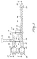
Figure 1 is an axial elevation view of a mixing apparatus associated with a system for producing tubular manufactured articles; -
Figure 2 is a partially sectional side view, taken along a vertical plane, of the apparatus according to the invention; -
Figure 3 is a sectional plan view of the apparatus, taken along the line III-III ofFigure 2 ; -
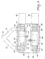
Figure 4 is a sectional plan view of the apparatus, taken along the line IV-IV ofFigure 2 ; -
Figure 5 is a view of the motor drive assembly of the apparatus according to the invention. - With reference to the figures, a mixing apparatus is generally designated by the reference numeral 1 and is composed substantially of the pairing of two mixing lines which are capable of providing respective flows of agglomerate composed of inert granular material, generally sand, and intimately mixed with a binder, generally resin.
- The two flows of agglomerate are deposited between two
layers 2, 3 (Figure 1 ) of structural fibers, generally glass fibers, impregnated with a binder, generally resin, and are wrapped in a helical arrangement on acylindrical mandrel 4 which rotates about a horizontal axis A in the direction B, so as to form a tubular manufactured article of which thelayer 2 constitutes the internal lining, thelayer 3 constitutes the outer wrapping and the agglomerate, provided by the mixing apparatus, constitutes the intermediate layer, which is designed to stiffen the tubular manufactured article and which, in the example described here, is assumed to be provided by superimposing a pair oflayers mandrel 4 and the means for its movement referenced here are assumed to be of a type known in the background art and are not described hereinafter for the sake of conciseness in description. In particular, it is assumed that the mandrel is actuated with a rotary motion about the axis A combined with an advancement motion in the direction B, such that the advancement stroke performed at each turn of the mandrel is equal to the pitch of the helical wrapping with which the layers are applied in order to provide the complete surface covering of the mandrel. - The apparatus 1 is composed (
Figure 4 ) of a frame which comprises two mutuallyparallel walls surface 9. In the opposite lateral portions of thewalls tubular elements walls tubular elements screw feeders intermediate layer 5. The inert material is unloaded into thefeeders respective distribution tubes 14, 15 (Figure 5 ) which branch out in a fork-like arrangement from acommon feeder pipe 16 which is connected to a container of the granular inert material. - The
jackets discharge openings tubes screw feeders feeders intake ports underlying mixing devices 23, 24 (Figures 2 ,3 ), in which the mixing with a binder is performed and the amalgamation of the agglomerate intended to form on themandrel 4 theintermediate layer - For the actuation of the two
screw feeders shafts screw feeders jackets Figure 4 ). Said assembly comprises a box-like structure 28, which is composed of a pair ofwalls wall 7 and to the front edges of which twoplates wall 7, are rigidly coupled. Theplates flange 33 which cantilevers out from theplate 32 and supports, with arib 34, anelongated plate 35, hereinafter referenced as strip, which is flat and parallel with respect to theplate 31. - Two
supports 36, 37 (Figures 4 ,5 ) are fixed to theplate 31 and to thestrip 35, and respective bearings for rotary support of theshaft 25 of thescrew feeder 19 are arranged therein. - A
friction clutch system 38 is arranged on the portion of theshaft 25 that lies outside thejacket 10, and apulley 39 is functionally associated therewith and is provided with a peripheral set of teeth on which atoothed belt 40 meshes. Thefriction clutch system 38 comprises pneumatically-actuated elements in order to allow the rotary coupling and uncoupling of thepulley 39 from theshaft 25 when thescrew feeder 19 is to be actuated or respectively stopped. - The
belt 40 is closed in a loop around asecond pulley 41, which is keyed to theoutput shaft 26a of agearmotor 42 which is coupled by means of a flange, in a cantilever arrangement, to thewall 30. The actuation of the gearmotor produces the direct actuation of thescrew feeder 20 and the rotary actuation of thescrew feeder 19 by means of the transmission composed of thepulley 41, thebelt 40, thepulley 39 and thefriction clutch system 38. A belt tensioning roller 43 (Figures 4 at 5 ) is conveniently fixed to theplate 32 in a cantilever arrangement, avoids the skipping of thebelt 40 and thus ensures a uniform dosage of the inert material toward themixing devices - The
mixing devices feeders Figure 3 , thereference numerals screw feeders feeders jackets wall 8, are provided withconnections 48, 49 (Figures 1 ,2 ), through which the binder and any catalysts to be mixed with the granular inert material conveyed by thefeeders - The two
mixers feeders intermediate layer jackets jackets walls - At the discharge outlets of the
jackets respective bending elements 52, 53 (Figures 1 ,2 ,3 ) for guiding and wrappingribbons 54 unwound fromrespective reels 55. Theribbons 54 are made of permeable material, for example fabric, non-woven fabric and the like, in order to be able to be impregnated by the binder and facilitate the adhesion of the agglomerate to thelayers bending element nozzle 56 for expelling the agglomerate, which is aligned with the axis of therespective screw feeder bending elements ribbons 54, which are made to slide by traction below them, so as to wrap them around the agglomerate that exits from thenozzles 56 of the twomixers - In a manner similar to the
feeders shafts screw feeders Figure 3 ). Theshaft 57 can rotate, by means of bearings, insupports plate 31 and to asecond strip 62, which is coplanar and arranged below thestrip 35. Afriction clutch system 63 is arranged on theshaft 57 and atoothed pulley 64 is functionally associated therewith and is engaged by atoothed belt 65. Thefriction clutch system 63 is similar to the one that actuates thefriction clutch system 38 of thefeeder 12 described above, i.e., it comprises a pneumatically-actuated element to allow the coupling and uncoupling of thepulley 64 with respect to theshaft 57 and therefore of thescrew feeder 46. Thebelt 65 is closed in a loop around asecond pulley 66 and tensioned by means of a belt tensioning roller 67 (Figure 5 ), which is fixed in a cantilever fashion on theplate 32. Thepulley 66 is keyed onto anoutput shaft 68 of agearmotor 69, which is flanged in a cantilever fashion to thewall 30 of theframe 28. Theshaft 68 is connected to theshaft 58 of thescrew feeder 47 and is supported in a bearing which is accommodated in asupport 70 which is fixed to thestrip 62 which is coplanar to thestrip 35. - The operation of the apparatus according to the invention, albeit entirely evident from the provided description, is as follows. The granular inert material, fed from the
tube 16 and from thebranches discharge outlets intake ports feeders screw feeders mixers connections - The mixing action performed by the
screw feeders output nozzles 56, forms an increasingly homogeneous amalgamation. As the agglomerate exits from thenozzles 56, it is wrapped by theribbons 54 guided under thebending elements layer layer 2. - As can be seen, the described apparatus therefore achieves the proposed aim and objects. In particular, by adjusting the speed of the
gearmotors - An important prerogative of the described apparatus is provided by the
friction clutch systems feeder 12 and respectively themixer 23 so as to provide one or two beads of agglomerate and obtain a single- or double-thicknessintermediate layer - Another important advantage of the described apparatus is that it can be installed at different levels with respect to the level of the
mandrel 4, particularly above it, thus allowing the simple deposition of the agglomerate directly on the mandrel and its distribution by means of spatulas or other devices capable of leveling its irregularities. - Where technical features mentioned in any claim are followed by reference signs, those reference signs have been included for the sole purpose of increasing the intelligibility of the claims and accordingly such reference signs do not have any limiting effect on the interpretation of each element identified by way of example by such reference signs.
Claims (8)
- An apparatus for mixing granular inert material with a resin binder in order to form, on a rotating cylindrical mandrel (4), a tubular manufactured article composed of an inner layer (2) which adheres to the surface of the mandrel, an outer layer (3) and an intermediate layer (5, 6) constituted by a uniform agglomerate obtained from an amalgamation of said granular inert material with said resin binder, characterized in that it comprises at least one mixing line composed of a feeder (12, 13) which is connected to a duct (14, 15) for feeding said granular inert material and a discharge outlet (17, 18), a mixing device (23, 24) which has an intake port (21, 22) which is suitable to receive said granular inert material from said discharge outlet (17, 18) of said feeder and connections (48, 49) for feeding said resin binder in said mixing device, said mixing device being suitable to form said uniform agglomerate and to apply it onto said inner layer (2) so as to form said intermediate layer.
- The apparatus according to claim 1, characterized in that said feeder (12, 13) is constituted by a cylindrical jacket (10, 11) inside which there is a screw feeder (19, 20) which is actuated by a motor assembly (27), said jacket being connected to a duct (14, 15, 16) for feeding said granular inert material and an outlet (17, 18) for discharging said material into a mixing device (23, 24) arranged below said feeder.
- The apparatus according to one of claims 1 and 2, characterized in that said mixing device (23, 24) is constituted by a cylindrical jacket (44, 45) inside which there is a screw feeder (46, 47) which is actuated by a motor assembly (59), said jacket (44, 45) being provided with an intake port (21, 22) which is connected to the discharge outlet (17, 18) of said feeder (12, 13) in order to receive therefrom the granular inert material and a discharge port (56) for depositing said uniform agglomerate on said inner layer (2).
- The apparatus according to claim 3, characterized in that said jacket (44) of said mixing device (23, 24) has, downstream of said intake port (21, 22), connectors (48, 49) for introducing in said jacket said resin binder and catalysts.
- The apparatus according to one of claims 3 and 4, characterized in that a bending element (52, 53) is associated with the output end of said jacket (44, 45) and comprises a funnel-shaped chute which is arranged below said end and is provided with a nozzle (56) which is aligned with said screw feeder (46, 47), said bending element being suitable to bend longitudinally a ribbon (54) which is permeable to said binder so as to wrap around said agglomerate and form a sort of bead which is suitable to be deposited on said inner layer (2) and wrap around said mandrel.
- The apparatus according to claim 5, characterized in that said ribbon (54) is constituted by a fabric, a non-woven fabric or the like which is permeable to the binder.
- The apparatus according to one of claims 2 to 6, characterized in that it comprises two screw feeders (12, 13), which are mutually parallel and superimposed on respective screw mixers (23, 24), each pair of said devices being actuated by its own actuation assembly (27, 59).
- The apparatus according to claim 7, characterized in that each actuation assembly (27, 59) comprises a frame (27), a motor element (42, 69) for driving a first screw feeder (20, 47), which is mounted on said frame and is provided with an output shaft (26a, 68), on which a first pulley (41, 66) is keyed, a friction clutch system (38, 63) which is arranged on the shaft (25, 57) of the second screw feeder (19, 47) and is functionally associated with a second pulley (39, 64) arranged coaxially to said shaft (25, 57), a driving belt (40, 65) which is closed in a loop around said pulleys (41, 66; 39, 64), said friction clutch system (38, 63) being controlled by actuation means which are suitable to produce the coupling and uncoupling of said second pulley (39, 64) with respect to said shaft (25, 57) in order to drive or respectively stop said second screw feeder (19, 47).
Priority Applications (4)
| Application Number | Priority Date | Filing Date | Title |
|---|---|---|---|
| EP08425073A EP2087979A1 (en) | 2008-02-08 | 2008-02-08 | Apparatus for mixing granular inert material and resin binder in the manufacture of laminated articles made of composite material |
| US12/320,803 US20090199969A1 (en) | 2008-02-08 | 2009-02-05 | Apparatus for mixing granular inert material and resin binder in the manufacture of laminated articles made of composite material |
| CN200910130797A CN101537673A (en) | 2008-02-08 | 2009-02-06 | Apparatus for mixing granular inert material and resin binder in the manufacture of laminated articles made of composite material |
| JP2009026293A JP2009184355A (en) | 2008-02-08 | 2009-02-06 | Apparatus for mixing granular inert material and resin binder in the manufacture of laminates made of composite materials |
Applications Claiming Priority (1)
| Application Number | Priority Date | Filing Date | Title |
|---|---|---|---|
| EP08425073A EP2087979A1 (en) | 2008-02-08 | 2008-02-08 | Apparatus for mixing granular inert material and resin binder in the manufacture of laminated articles made of composite material |
Publications (1)
| Publication Number | Publication Date |
|---|---|
| EP2087979A1 true EP2087979A1 (en) | 2009-08-12 |
Family
ID=39575662
Family Applications (1)
| Application Number | Title | Priority Date | Filing Date |
|---|---|---|---|
| EP08425073A Withdrawn EP2087979A1 (en) | 2008-02-08 | 2008-02-08 | Apparatus for mixing granular inert material and resin binder in the manufacture of laminated articles made of composite material |
Country Status (4)
| Country | Link |
|---|---|
| US (1) | US20090199969A1 (en) |
| EP (1) | EP2087979A1 (en) |
| JP (1) | JP2009184355A (en) |
| CN (1) | CN101537673A (en) |
Cited By (2)
| Publication number | Priority date | Publication date | Assignee | Title |
|---|---|---|---|---|
| EP2428351A2 (en) | 2010-09-09 | 2012-03-14 | Siegfried Kreft | Method and device for the manufacture of moulds and granulate |
| CN114393828A (en) * | 2022-01-14 | 2022-04-26 | 中南大学 | A nozzle structure for 3D printing |
Families Citing this family (11)
| Publication number | Priority date | Publication date | Assignee | Title |
|---|---|---|---|---|
| US8221109B2 (en) * | 2006-12-05 | 2012-07-17 | Gold Tip, Llc | Material layering device |
| CN103432922A (en) * | 2013-09-02 | 2013-12-11 | 武汉合缘绿色生物工程有限公司 | Continuous burdening mixing machine |
| CN105599317B (en) * | 2015-12-24 | 2018-05-15 | 浙江鑫宙竹基复合材料科技有限公司 | A kind of adhesive adding method of bamboo winding joint product winding process |
| CN106110934A (en) * | 2016-06-27 | 2016-11-16 | 安徽省思维新型建材有限公司 | Mixing arrangement thrown in by material |
| CN106076151A (en) * | 2016-06-27 | 2016-11-09 | 安徽省思维新型建材有限公司 | Material mixing buffer unit |
| CN105944596A (en) * | 2016-06-27 | 2016-09-21 | 安徽省思维新型建材有限公司 | Material mixing device |
| CN106076139A (en) * | 2016-06-27 | 2016-11-09 | 安徽省思维新型建材有限公司 | Water paint material-transporting system |
| EP3561355A4 (en) * | 2016-12-26 | 2019-12-18 | Bridgestone Corporation | Composite pipe and method for manufacturing composite pipe |
| CN111760500A (en) * | 2020-06-19 | 2020-10-13 | 隋心怡 | Adhesive mixing stirring device |
| CN113442471B (en) * | 2021-06-03 | 2022-08-02 | 公元管道(安徽)有限公司 | Online continuous injection moulding equipment of power cable pipe |
| CH722015A1 (en) * | 2024-07-26 | 2026-01-30 | Innogel Ag | Device and method for producing a multi-component mass, as well as a system with the device |
Citations (6)
| Publication number | Priority date | Publication date | Assignee | Title |
|---|---|---|---|---|
| US1840634A (en) * | 1928-04-30 | 1932-01-12 | Inland Mfg Co | Laminated steering wheel rim |
| US2707017A (en) * | 1951-03-03 | 1955-04-26 | Gen Motors Corp | Method of making wire reinforced flexible hose |
| US4243075A (en) * | 1979-02-02 | 1981-01-06 | Clow Corporation | Composite pipe |
| JPS5845023A (en) * | 1981-09-11 | 1983-03-16 | Sekisui Chem Co Ltd | Manufacture of composite pipe |
| FR2835469A1 (en) * | 2002-02-04 | 2003-08-08 | Allibert Equipement | Manufacture of swimming pool shell uses extruded thermoplastic strip wound onto rotating mandrel and welding to base |
| WO2004056551A1 (en) * | 2002-12-20 | 2004-07-08 | Meccaniche Moderne S.P.A. | Method for producing composite materials such as thermoplastic resins with mineral and/or vegetable fillers |
Family Cites Families (1)
| Publication number | Priority date | Publication date | Assignee | Title |
|---|---|---|---|---|
| US5811164A (en) * | 1996-09-27 | 1998-09-22 | Plastic Specialties And Technologies Investments, Inc. | Aeration pipe and method of making same |
-
2008
- 2008-02-08 EP EP08425073A patent/EP2087979A1/en not_active Withdrawn
-
2009
- 2009-02-05 US US12/320,803 patent/US20090199969A1/en not_active Abandoned
- 2009-02-06 JP JP2009026293A patent/JP2009184355A/en active Pending
- 2009-02-06 CN CN200910130797A patent/CN101537673A/en active Pending
Patent Citations (6)
| Publication number | Priority date | Publication date | Assignee | Title |
|---|---|---|---|---|
| US1840634A (en) * | 1928-04-30 | 1932-01-12 | Inland Mfg Co | Laminated steering wheel rim |
| US2707017A (en) * | 1951-03-03 | 1955-04-26 | Gen Motors Corp | Method of making wire reinforced flexible hose |
| US4243075A (en) * | 1979-02-02 | 1981-01-06 | Clow Corporation | Composite pipe |
| JPS5845023A (en) * | 1981-09-11 | 1983-03-16 | Sekisui Chem Co Ltd | Manufacture of composite pipe |
| FR2835469A1 (en) * | 2002-02-04 | 2003-08-08 | Allibert Equipement | Manufacture of swimming pool shell uses extruded thermoplastic strip wound onto rotating mandrel and welding to base |
| WO2004056551A1 (en) * | 2002-12-20 | 2004-07-08 | Meccaniche Moderne S.P.A. | Method for producing composite materials such as thermoplastic resins with mineral and/or vegetable fillers |
Cited By (4)
| Publication number | Priority date | Publication date | Assignee | Title |
|---|---|---|---|---|
| EP2428351A2 (en) | 2010-09-09 | 2012-03-14 | Siegfried Kreft | Method and device for the manufacture of moulds and granulate |
| DE102010037441A1 (en) * | 2010-09-09 | 2012-03-15 | Horn Dietmar | Method and device for the production of molded parts and granules |
| CN114393828A (en) * | 2022-01-14 | 2022-04-26 | 中南大学 | A nozzle structure for 3D printing |
| CN114393828B (en) * | 2022-01-14 | 2022-11-11 | 中南大学 | A nozzle structure for 3D printing |
Also Published As
| Publication number | Publication date |
|---|---|
| US20090199969A1 (en) | 2009-08-13 |
| CN101537673A (en) | 2009-09-23 |
| JP2009184355A (en) | 2009-08-20 |
Similar Documents
| Publication | Publication Date | Title |
|---|---|---|
| EP2087979A1 (en) | Apparatus for mixing granular inert material and resin binder in the manufacture of laminated articles made of composite material | |
| US6986812B2 (en) | Slurry feed apparatus for fiber-reinforced structural cementitious panel production | |
| CN100553952C (en) | Wire winding equipment | |
| CN112533744B (en) | Apparatus and method for in-situ helical impregnation and extrusion of continuous fibers | |
| CN101795854B (en) | Apparatus for manufacturing pipe-shaped insulator | |
| CN211394849U (en) | Thread feeding unit of needle punching machine for producing knitted tubes and needle punching machine | |
| KR100938020B1 (en) | The manufacture apparatus of fiberglass reinforced plastic | |
| CN103878991B (en) | A kind of production line of same with thermosetting compound material continuous-tube | |
| WO2017107787A1 (en) | Adhesive adding method for bamboo-wrapped composite product wrapping process | |
| CN208615105U (en) | A kind of glue tank for manufacturing basalt fiber composite pipe | |
| CN112895425B (en) | Eccentric multi-roller dipping composite fiber filament fused deposition extrusion printing spray head device | |
| KR101078713B1 (en) | Reinforcing fiber feeder for axial reinforcement of continuous pipe | |
| CN118248411A (en) | Cable core cladding forming device | |
| JPS62776B2 (en) | ||
| CN102051830A (en) | Strand making, stranding and rope making all-in-one machine | |
| CN202323529U (en) | Strand-making, strand-combining and rope-making integrated machine | |
| CN117549397A (en) | Rotatable multi-filament continuous fiber reinforced concrete 3D printing nozzle | |
| KR19990065849A (en) | Apparatus and method for manufacturing metal fiber for cement composition reinforcement | |
| CN101446376B (en) | Pneumatic-brake hose and preparation method thereof | |
| KR101658100B1 (en) | Superconductive wire manufacturing appratus and superconductive wire manufacturing method | |
| CN219947050U (en) | Injection molding material transmission device | |
| CN223161485U (en) | Equipment for manufacturing degradable non-woven fabric packaging material containing vinasse | |
| CN119260944B (en) | Concrete distributing equipment | |
| CN220841523U (en) | Composite winding pipe production device and system | |
| CN117227026B (en) | A PEC composite structure molding and processing device |
Legal Events
| Date | Code | Title | Description |
|---|---|---|---|
| PUAI | Public reference made under article 153(3) epc to a published international application that has entered the european phase |
Free format text: ORIGINAL CODE: 0009012 |
|
| AK | Designated contracting states |
Kind code of ref document: A1 Designated state(s): AT BE BG CH CY CZ DE DK EE ES FI FR GB GR HR HU IE IS IT LI LT LU LV MC MT NL NO PL PT RO SE SI SK TR |
|
| AX | Request for extension of the european patent |
Extension state: AL BA MK RS |
|
| 17P | Request for examination filed |
Effective date: 20100203 |
|
| AKX | Designation fees paid |
Designated state(s): AT BE BG CH CY CZ DE DK EE ES FI FR GB GR HR HU IE IS IT LI LT LU LV MC MT NL NO PL PT RO SE SI SK TR |
|
| STAA | Information on the status of an ep patent application or granted ep patent |
Free format text: STATUS: THE APPLICATION IS DEEMED TO BE WITHDRAWN |
|
| 18D | Application deemed to be withdrawn |
Effective date: 20120901 |