EP2106490B1 - Verbesserte vorrichtung zur elektronischen steuerung von schiebetoren - Google Patents
Verbesserte vorrichtung zur elektronischen steuerung von schiebetoren Download PDFInfo
- Publication number
- EP2106490B1 EP2106490B1 EP08720211A EP08720211A EP2106490B1 EP 2106490 B1 EP2106490 B1 EP 2106490B1 EP 08720211 A EP08720211 A EP 08720211A EP 08720211 A EP08720211 A EP 08720211A EP 2106490 B1 EP2106490 B1 EP 2106490B1
- Authority
- EP
- European Patent Office
- Prior art keywords
- gate
- designed
- motor
- opening
- closing
- Prior art date
- Legal status (The legal status is an assumption and is not a legal conclusion. Google has not performed a legal analysis and makes no representation as to the accuracy of the status listed.)
- Active
Links
- 230000033001 locomotion Effects 0.000 claims description 21
- 230000005540 biological transmission Effects 0.000 claims description 6
- 230000006870 function Effects 0.000 claims description 6
- 230000006698 induction Effects 0.000 claims description 6
- 238000006073 displacement reaction Methods 0.000 claims description 4
- 238000013459 approach Methods 0.000 claims description 2
- 230000008878 coupling Effects 0.000 claims description 2
- 238000010168 coupling process Methods 0.000 claims description 2
- 238000005859 coupling reaction Methods 0.000 claims description 2
- 230000003287 optical effect Effects 0.000 claims description 2
- 230000001105 regulatory effect Effects 0.000 claims description 2
- 230000002441 reversible effect Effects 0.000 claims description 2
- 238000002604 ultrasonography Methods 0.000 claims description 2
- 230000001464 adherent effect Effects 0.000 claims 1
- 230000000903 blocking effect Effects 0.000 claims 1
- 230000000875 corresponding effect Effects 0.000 description 8
- 230000008901 benefit Effects 0.000 description 5
- 238000000034 method Methods 0.000 description 3
- 238000001514 detection method Methods 0.000 description 2
- 230000004048 modification Effects 0.000 description 2
- 238000012986 modification Methods 0.000 description 2
- 230000006978 adaptation Effects 0.000 description 1
- 230000002411 adverse Effects 0.000 description 1
- 230000033228 biological regulation Effects 0.000 description 1
- 239000003638 chemical reducing agent Substances 0.000 description 1
- 230000001276 controlling effect Effects 0.000 description 1
- 230000002596 correlated effect Effects 0.000 description 1
- 230000007423 decrease Effects 0.000 description 1
- 238000010586 diagram Methods 0.000 description 1
- 230000007717 exclusion Effects 0.000 description 1
- 238000009434 installation Methods 0.000 description 1
- 238000012423 maintenance Methods 0.000 description 1
- 230000008569 process Effects 0.000 description 1
- 238000012545 processing Methods 0.000 description 1
- 230000008054 signal transmission Effects 0.000 description 1
- 230000011664 signaling Effects 0.000 description 1
Images


Classifications
-
- E—FIXED CONSTRUCTIONS
- E05—LOCKS; KEYS; WINDOW OR DOOR FITTINGS; SAFES
- E05B—LOCKS; ACCESSORIES THEREFOR; HANDCUFFS
- E05B65/00—Locks or fastenings for special use
- E05B65/0007—Locks or fastenings for special use for gates
-
- E—FIXED CONSTRUCTIONS
- E05—LOCKS; KEYS; WINDOW OR DOOR FITTINGS; SAFES
- E05B—LOCKS; ACCESSORIES THEREFOR; HANDCUFFS
- E05B65/00—Locks or fastenings for special use
- E05B65/08—Locks or fastenings for special use for sliding wings
- E05B65/0811—Locks or fastenings for special use for sliding wings the bolts pivoting about an axis perpendicular to the wings
-
- E—FIXED CONSTRUCTIONS
- E05—LOCKS; KEYS; WINDOW OR DOOR FITTINGS; SAFES
- E05F—DEVICES FOR MOVING WINGS INTO OPEN OR CLOSED POSITION; CHECKS FOR WINGS; WING FITTINGS NOT OTHERWISE PROVIDED FOR, CONCERNED WITH THE FUNCTIONING OF THE WING
- E05F15/00—Power-operated mechanisms for wings
- E05F15/60—Power-operated mechanisms for wings using electrical actuators
- E05F15/603—Power-operated mechanisms for wings using electrical actuators using rotary electromotors
- E05F15/632—Power-operated mechanisms for wings using electrical actuators using rotary electromotors for horizontally-sliding wings
- E05F15/635—Power-operated mechanisms for wings using electrical actuators using rotary electromotors for horizontally-sliding wings operated by push-pull mechanisms, e.g. flexible or rigid rack-and-pinion arrangements
- E05F15/641—Power-operated mechanisms for wings using electrical actuators using rotary electromotors for horizontally-sliding wings operated by push-pull mechanisms, e.g. flexible or rigid rack-and-pinion arrangements operated by friction wheels
-
- E—FIXED CONSTRUCTIONS
- E05—LOCKS; KEYS; WINDOW OR DOOR FITTINGS; SAFES
- E05B—LOCKS; ACCESSORIES THEREFOR; HANDCUFFS
- E05B47/00—Operating or controlling locks or other fastening devices by electric or magnetic means
- E05B47/0001—Operating or controlling locks or other fastening devices by electric or magnetic means with electric actuators; Constructional features thereof
- E05B2047/0014—Constructional features of actuators or power transmissions therefor
- E05B2047/0015—Output elements of actuators
- E05B2047/0017—Output elements of actuators with rotary motion
-
- E—FIXED CONSTRUCTIONS
- E05—LOCKS; KEYS; WINDOW OR DOOR FITTINGS; SAFES
- E05B—LOCKS; ACCESSORIES THEREFOR; HANDCUFFS
- E05B47/00—Operating or controlling locks or other fastening devices by electric or magnetic means
- E05B47/0001—Operating or controlling locks or other fastening devices by electric or magnetic means with electric actuators; Constructional features thereof
- E05B2047/0014—Constructional features of actuators or power transmissions therefor
- E05B2047/0018—Details of actuator transmissions
- E05B2047/002—Geared transmissions
-
- E—FIXED CONSTRUCTIONS
- E05—LOCKS; KEYS; WINDOW OR DOOR FITTINGS; SAFES
- E05B—LOCKS; ACCESSORIES THEREFOR; HANDCUFFS
- E05B47/00—Operating or controlling locks or other fastening devices by electric or magnetic means
- E05B47/0001—Operating or controlling locks or other fastening devices by electric or magnetic means with electric actuators; Constructional features thereof
- E05B47/0012—Operating or controlling locks or other fastening devices by electric or magnetic means with electric actuators; Constructional features thereof with rotary electromotors
-
- E—FIXED CONSTRUCTIONS
- E05—LOCKS; KEYS; WINDOW OR DOOR FITTINGS; SAFES
- E05F—DEVICES FOR MOVING WINGS INTO OPEN OR CLOSED POSITION; CHECKS FOR WINGS; WING FITTINGS NOT OTHERWISE PROVIDED FOR, CONCERNED WITH THE FUNCTIONING OF THE WING
- E05F15/00—Power-operated mechanisms for wings
- E05F15/40—Safety devices, e.g. detection of obstructions or end positions
- E05F15/42—Detection using safety edges
- E05F15/43—Detection using safety edges responsive to disruption of energy beams, e.g. light or sound
-
- E—FIXED CONSTRUCTIONS
- E05—LOCKS; KEYS; WINDOW OR DOOR FITTINGS; SAFES
- E05F—DEVICES FOR MOVING WINGS INTO OPEN OR CLOSED POSITION; CHECKS FOR WINGS; WING FITTINGS NOT OTHERWISE PROVIDED FOR, CONCERNED WITH THE FUNCTIONING OF THE WING
- E05F15/00—Power-operated mechanisms for wings
- E05F15/70—Power-operated mechanisms for wings with automatic actuation
- E05F15/73—Power-operated mechanisms for wings with automatic actuation responsive to movement or presence of persons or objects
- E05F15/74—Power-operated mechanisms for wings with automatic actuation responsive to movement or presence of persons or objects using photoelectric cells
-
- E—FIXED CONSTRUCTIONS
- E05—LOCKS; KEYS; WINDOW OR DOOR FITTINGS; SAFES
- E05F—DEVICES FOR MOVING WINGS INTO OPEN OR CLOSED POSITION; CHECKS FOR WINGS; WING FITTINGS NOT OTHERWISE PROVIDED FOR, CONCERNED WITH THE FUNCTIONING OF THE WING
- E05F15/00—Power-operated mechanisms for wings
- E05F15/70—Power-operated mechanisms for wings with automatic actuation
- E05F15/77—Power-operated mechanisms for wings with automatic actuation using wireless control
-
- E—FIXED CONSTRUCTIONS
- E05—LOCKS; KEYS; WINDOW OR DOOR FITTINGS; SAFES
- E05F—DEVICES FOR MOVING WINGS INTO OPEN OR CLOSED POSITION; CHECKS FOR WINGS; WING FITTINGS NOT OTHERWISE PROVIDED FOR, CONCERNED WITH THE FUNCTIONING OF THE WING
- E05F15/00—Power-operated mechanisms for wings
- E05F15/40—Safety devices, e.g. detection of obstructions or end positions
- E05F15/42—Detection using safety edges
- E05F15/43—Detection using safety edges responsive to disruption of energy beams, e.g. light or sound
- E05F2015/434—Detection using safety edges responsive to disruption of energy beams, e.g. light or sound with cameras or optical sensors
- E05F2015/435—Detection using safety edges responsive to disruption of energy beams, e.g. light or sound with cameras or optical sensors by interruption of the beam
-
- E—FIXED CONSTRUCTIONS
- E05—LOCKS; KEYS; WINDOW OR DOOR FITTINGS; SAFES
- E05Y—INDEXING SCHEME ASSOCIATED WITH SUBCLASSES E05D AND E05F, RELATING TO CONSTRUCTION ELEMENTS, ELECTRIC CONTROL, POWER SUPPLY, POWER SIGNAL OR TRANSMISSION, USER INTERFACES, MOUNTING OR COUPLING, DETAILS, ACCESSORIES, AUXILIARY OPERATIONS NOT OTHERWISE PROVIDED FOR, APPLICATION THEREOF
- E05Y2201/00—Constructional elements; Accessories therefor
- E05Y2201/20—Brakes; Disengaging means; Holders; Stops; Valves; Accessories therefor
- E05Y2201/214—Disengaging means
-
- E—FIXED CONSTRUCTIONS
- E05—LOCKS; KEYS; WINDOW OR DOOR FITTINGS; SAFES
- E05Y—INDEXING SCHEME ASSOCIATED WITH SUBCLASSES E05D AND E05F, RELATING TO CONSTRUCTION ELEMENTS, ELECTRIC CONTROL, POWER SUPPLY, POWER SIGNAL OR TRANSMISSION, USER INTERFACES, MOUNTING OR COUPLING, DETAILS, ACCESSORIES, AUXILIARY OPERATIONS NOT OTHERWISE PROVIDED FOR, APPLICATION THEREOF
- E05Y2201/00—Constructional elements; Accessories therefor
- E05Y2201/20—Brakes; Disengaging means; Holders; Stops; Valves; Accessories therefor
- E05Y2201/218—Holders
- E05Y2201/22—Locks
-
- E—FIXED CONSTRUCTIONS
- E05—LOCKS; KEYS; WINDOW OR DOOR FITTINGS; SAFES
- E05Y—INDEXING SCHEME ASSOCIATED WITH SUBCLASSES E05D AND E05F, RELATING TO CONSTRUCTION ELEMENTS, ELECTRIC CONTROL, POWER SUPPLY, POWER SIGNAL OR TRANSMISSION, USER INTERFACES, MOUNTING OR COUPLING, DETAILS, ACCESSORIES, AUXILIARY OPERATIONS NOT OTHERWISE PROVIDED FOR, APPLICATION THEREOF
- E05Y2201/00—Constructional elements; Accessories therefor
- E05Y2201/20—Brakes; Disengaging means; Holders; Stops; Valves; Accessories therefor
- E05Y2201/23—Actuation thereof
- E05Y2201/244—Actuation thereof by manual operation
-
- E—FIXED CONSTRUCTIONS
- E05—LOCKS; KEYS; WINDOW OR DOOR FITTINGS; SAFES
- E05Y—INDEXING SCHEME ASSOCIATED WITH SUBCLASSES E05D AND E05F, RELATING TO CONSTRUCTION ELEMENTS, ELECTRIC CONTROL, POWER SUPPLY, POWER SIGNAL OR TRANSMISSION, USER INTERFACES, MOUNTING OR COUPLING, DETAILS, ACCESSORIES, AUXILIARY OPERATIONS NOT OTHERWISE PROVIDED FOR, APPLICATION THEREOF
- E05Y2201/00—Constructional elements; Accessories therefor
- E05Y2201/40—Motors; Magnets; Springs; Weights; Accessories therefor
- E05Y2201/43—Motors
- E05Y2201/434—Electromotors; Details thereof
-
- E—FIXED CONSTRUCTIONS
- E05—LOCKS; KEYS; WINDOW OR DOOR FITTINGS; SAFES
- E05Y—INDEXING SCHEME ASSOCIATED WITH SUBCLASSES E05D AND E05F, RELATING TO CONSTRUCTION ELEMENTS, ELECTRIC CONTROL, POWER SUPPLY, POWER SIGNAL OR TRANSMISSION, USER INTERFACES, MOUNTING OR COUPLING, DETAILS, ACCESSORIES, AUXILIARY OPERATIONS NOT OTHERWISE PROVIDED FOR, APPLICATION THEREOF
- E05Y2201/00—Constructional elements; Accessories therefor
- E05Y2201/60—Suspension or transmission members; Accessories therefor
- E05Y2201/622—Suspension or transmission members elements
- E05Y2201/638—Cams; Ramps
-
- E—FIXED CONSTRUCTIONS
- E05—LOCKS; KEYS; WINDOW OR DOOR FITTINGS; SAFES
- E05Y—INDEXING SCHEME ASSOCIATED WITH SUBCLASSES E05D AND E05F, RELATING TO CONSTRUCTION ELEMENTS, ELECTRIC CONTROL, POWER SUPPLY, POWER SIGNAL OR TRANSMISSION, USER INTERFACES, MOUNTING OR COUPLING, DETAILS, ACCESSORIES, AUXILIARY OPERATIONS NOT OTHERWISE PROVIDED FOR, APPLICATION THEREOF
- E05Y2201/00—Constructional elements; Accessories therefor
- E05Y2201/60—Suspension or transmission members; Accessories therefor
- E05Y2201/622—Suspension or transmission members elements
- E05Y2201/674—Friction wheels
-
- E—FIXED CONSTRUCTIONS
- E05—LOCKS; KEYS; WINDOW OR DOOR FITTINGS; SAFES
- E05Y—INDEXING SCHEME ASSOCIATED WITH SUBCLASSES E05D AND E05F, RELATING TO CONSTRUCTION ELEMENTS, ELECTRIC CONTROL, POWER SUPPLY, POWER SIGNAL OR TRANSMISSION, USER INTERFACES, MOUNTING OR COUPLING, DETAILS, ACCESSORIES, AUXILIARY OPERATIONS NOT OTHERWISE PROVIDED FOR, APPLICATION THEREOF
- E05Y2400/00—Electronic control; Electrical power; Power supply; Power or signal transmission; User interfaces
- E05Y2400/61—Power supply
- E05Y2400/612—Batteries
- E05Y2400/614—Batteries charging thereof
-
- E—FIXED CONSTRUCTIONS
- E05—LOCKS; KEYS; WINDOW OR DOOR FITTINGS; SAFES
- E05Y—INDEXING SCHEME ASSOCIATED WITH SUBCLASSES E05D AND E05F, RELATING TO CONSTRUCTION ELEMENTS, ELECTRIC CONTROL, POWER SUPPLY, POWER SIGNAL OR TRANSMISSION, USER INTERFACES, MOUNTING OR COUPLING, DETAILS, ACCESSORIES, AUXILIARY OPERATIONS NOT OTHERWISE PROVIDED FOR, APPLICATION THEREOF
- E05Y2400/00—Electronic control; Electrical power; Power supply; Power or signal transmission; User interfaces
- E05Y2400/65—Power or signal transmission
- E05Y2400/656—Power or signal transmission by travelling contacts
-
- E—FIXED CONSTRUCTIONS
- E05—LOCKS; KEYS; WINDOW OR DOOR FITTINGS; SAFES
- E05Y—INDEXING SCHEME ASSOCIATED WITH SUBCLASSES E05D AND E05F, RELATING TO CONSTRUCTION ELEMENTS, ELECTRIC CONTROL, POWER SUPPLY, POWER SIGNAL OR TRANSMISSION, USER INTERFACES, MOUNTING OR COUPLING, DETAILS, ACCESSORIES, AUXILIARY OPERATIONS NOT OTHERWISE PROVIDED FOR, APPLICATION THEREOF
- E05Y2400/00—Electronic control; Electrical power; Power supply; Power or signal transmission; User interfaces
- E05Y2400/65—Power or signal transmission
- E05Y2400/66—Wireless transmission
-
- E—FIXED CONSTRUCTIONS
- E05—LOCKS; KEYS; WINDOW OR DOOR FITTINGS; SAFES
- E05Y—INDEXING SCHEME ASSOCIATED WITH SUBCLASSES E05D AND E05F, RELATING TO CONSTRUCTION ELEMENTS, ELECTRIC CONTROL, POWER SUPPLY, POWER SIGNAL OR TRANSMISSION, USER INTERFACES, MOUNTING OR COUPLING, DETAILS, ACCESSORIES, AUXILIARY OPERATIONS NOT OTHERWISE PROVIDED FOR, APPLICATION THEREOF
- E05Y2400/00—Electronic control; Electrical power; Power supply; Power or signal transmission; User interfaces
- E05Y2400/80—User interfaces
- E05Y2400/81—Feedback to user, e.g. tactile
- E05Y2400/818—Visual
- E05Y2400/822—Light emitters, e.g. light emitting diodes [LED]
-
- E—FIXED CONSTRUCTIONS
- E05—LOCKS; KEYS; WINDOW OR DOOR FITTINGS; SAFES
- E05Y—INDEXING SCHEME ASSOCIATED WITH SUBCLASSES E05D AND E05F, RELATING TO CONSTRUCTION ELEMENTS, ELECTRIC CONTROL, POWER SUPPLY, POWER SIGNAL OR TRANSMISSION, USER INTERFACES, MOUNTING OR COUPLING, DETAILS, ACCESSORIES, AUXILIARY OPERATIONS NOT OTHERWISE PROVIDED FOR, APPLICATION THEREOF
- E05Y2400/00—Electronic control; Electrical power; Power supply; Power or signal transmission; User interfaces
- E05Y2400/80—User interfaces
- E05Y2400/81—Feedback to user, e.g. tactile
- E05Y2400/83—Travel information display
-
- E—FIXED CONSTRUCTIONS
- E05—LOCKS; KEYS; WINDOW OR DOOR FITTINGS; SAFES
- E05Y—INDEXING SCHEME ASSOCIATED WITH SUBCLASSES E05D AND E05F, RELATING TO CONSTRUCTION ELEMENTS, ELECTRIC CONTROL, POWER SUPPLY, POWER SIGNAL OR TRANSMISSION, USER INTERFACES, MOUNTING OR COUPLING, DETAILS, ACCESSORIES, AUXILIARY OPERATIONS NOT OTHERWISE PROVIDED FOR, APPLICATION THEREOF
- E05Y2600/00—Mounting or coupling arrangements for elements provided for in this subclass
- E05Y2600/40—Mounting location; Visibility of the elements
- E05Y2600/454—Mounting location; Visibility of the elements in or on the motor
-
- E—FIXED CONSTRUCTIONS
- E05—LOCKS; KEYS; WINDOW OR DOOR FITTINGS; SAFES
- E05Y—INDEXING SCHEME ASSOCIATED WITH SUBCLASSES E05D AND E05F, RELATING TO CONSTRUCTION ELEMENTS, ELECTRIC CONTROL, POWER SUPPLY, POWER SIGNAL OR TRANSMISSION, USER INTERFACES, MOUNTING OR COUPLING, DETAILS, ACCESSORIES, AUXILIARY OPERATIONS NOT OTHERWISE PROVIDED FOR, APPLICATION THEREOF
- E05Y2600/00—Mounting or coupling arrangements for elements provided for in this subclass
- E05Y2600/40—Mounting location; Visibility of the elements
- E05Y2600/46—Mounting location; Visibility of the elements in or on the wing
-
- E—FIXED CONSTRUCTIONS
- E05—LOCKS; KEYS; WINDOW OR DOOR FITTINGS; SAFES
- E05Y—INDEXING SCHEME ASSOCIATED WITH SUBCLASSES E05D AND E05F, RELATING TO CONSTRUCTION ELEMENTS, ELECTRIC CONTROL, POWER SUPPLY, POWER SIGNAL OR TRANSMISSION, USER INTERFACES, MOUNTING OR COUPLING, DETAILS, ACCESSORIES, AUXILIARY OPERATIONS NOT OTHERWISE PROVIDED FOR, APPLICATION THEREOF
- E05Y2900/00—Application of doors, windows, wings or fittings thereof
- E05Y2900/40—Application of doors, windows, wings or fittings thereof for gates
Definitions
- the present invention relates to the sector of automatic gates and more in particular to a gate equipped with means for automatic powering thereof and means for electronic control of proper operation thereof in conditions of safety.
- Said device is characterized in that it comprises a drive wheel and a motor, which transmits the motion to said drive wheel, both of which are mounted on the gate, where the drive wheel is shaped and engages with a slide guide set on the ground.
- a first drawback of said device is represented by the fact that the gear transmission (crown wheel and pinion) is, obviously, very rigid and requires maintenance to prevent any sticking.
- a second disadvantage is represented by the fact that the manual release of the gate, in the event of failure or in the case of lack of power supply, is particularly problematical.
- a third drawback is that, in the case where it is necessary to perform manual opening of the gate, in addition to the disadvantage referred to above, the user also has to carry out a further intervention on the lock.
- a fourth disadvantage consists in the fact that the technical solution described in the aforesaid patent entails particularly complicated operations of assembly, whereas according to the present invention opening of the lock occurs automatically during the operations of release of the gate.
- a fifth disadvantage of the known art referred to above consists in the fact that it is not possible to have an automatic regulation of the speed of the movement of the gate as a function bf its effective weight.
- the task of the present invention is to overcome the above drawbacks, by providing an apparatus for movement of sliding gates according to claim 1.
- said mobile movement means comprise a bottom drive wheel designed to be displaced by a low-voltage d. c. electric motor, said drive wheel acting as an alternative to the bottom idler wheel that is commonly present in the proximity of the front side of sliding gates of a known type.
- the electric motor is contained in a guard rendered fixed with respect to the gate, and the supply of said motor is provided by a storage battery, which is set inside the guard itself, said storage battery being recharged by means of an induction system that is activated when the gate is closed.
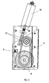
- the apparatus according to the invention is provided with a main body 1, of a substantially parallelepipedal shape, designed to be fixed on the vertical front edge of the sliding gate which is to be motor-powered, there being housed in said body 1 at least the bottom movement means, the supply battery or accumulator, the means for closing the gate, the means for warning that the gate is moving, and the control electronics.
- the main body 1 is designed to be blocked in a lowered position with respect to the vertical front side of the gate C in such a way that its bottom drive wheel R is lower than the front idler wheel F of the gate itself, the result being that said front wheel F of the gate C is slightly raised from the guide rail 3, of a known type, along which the gate moves.
- a first peculiar characteristic of the invention lies in the fact that the main body 1 is slidably mounted on a vertical guide 2, firmly fixed to the front side of the gate C, and during normal use said main body 1 is displaced downwards along said vertical guide 2 and is kept in said position by purposely provided raising means 4, which are preferably wedge-shaped and are designed to co-operate with the inclined bottom end of the vertical guide 2 fixed with respect to the gate C.
- said wedge is displaced forwards or backwards in the horizontal direction, i.e., perpendicular to the guide 2, via screw means and is designed to be mounted on the side of the gate facing the inside of the property that is enclosed.
- the pawl 6 of the lock provided in the main body 1 of the apparatus described herein is pivoted on a pin 8 set along its length, and has its rear end designed to interfere with an opening or interruption 7 of the vertical guide 2 that is set at a height such that, when the main body 1 of the apparatus slides vertically upwards with respect to the gate C and hence also with respect to the guide 2 fixed with respect thereto, said rear end of the pawl is lowered, bringing about raising of the front end of the pawl 6 and consequent disengagement from the fixed part 9 against which the gate closes by bearing thereupon.
- the above configuration of the parts guarantees that, if need be, it is sufficient to act on the raising means 4 to obtain both release of the gate C, by bringing it back to rest upon its idler wheels F, and opening of the lock of the gate itself.
- the supply battery of the motor, of the electronic-control part, and of the warning means 10 (flasher) for indicating that the gate is moving is recharged preferably by the electrical mains supply by means of a front connection set in a position corresponding to the fixed part of the lock, or else an induction connection, or else again by means of photovoltaic cells.
- the transmission of the motion between the motor M and the drive wheel R occurs by means of a kinematic chain with pulleys and a preferably cogged V-belt 11, with a drive ratio suitable for limiting the motor power requirement.
- the motor M it is preferable for the motor M to move the corresponding pulley by means of a wormscrew/helical-wheel coupling 12 so as to render the transmission of the motion non-reversible.
- At least one photocell of a known type designed to detect the presence of obstacles along the path of the gate C during the displacements of the gate itself.
- Said photocell is preferably set in a position corresponding to the fixed part 9 of the lock, and the mobile part of the same lock is fixed with respect to the main body 1.
- the electronic control device of the electric motor M of the gate comprises:
- auxiliary means for signalling opening/closing of the gate, for detection of obstacles on the opening/closing path of the gate, and for exclusion upon command of the electronic control device.
- Said auxiliary means comprise:
- said battery charger prefferably to be optimized for the type of battery used.
- the microcontroller MC comprises:
- the PWM circuit is substantially a circuit designed to generate a sequence of square-wave pulses, the frequency and duty cycle (i.e., the ratio between the duration of a pulse and the period comprised between the pulse considered and the next pulse) of which are parameters that can be modified by the microcontroller MC.
- the operating parameters regard the weight of the gate, the time during which the gate remains open before reclosing during a cycle of opening/closing thereof, the length of the travel of the gate for passing from an opening position to a closing position or vice versa, as well as the remote-control code that enables opening/closing of the gate itself.
- the speed of the motor M is regulated by the microcontroller MC by varying the time during which the entire supply voltage is applied to the terminals of the motor M.
- the PWM circuit sends said pulses to the power MOSFET that controls the speed of the motor M by means of a purposely provided relay circuit RE that establishes the direction of rotation of the motor M itself.
- two relays RE are provided: a relay for opening R1 the gate, and a relay for closing R2 the gate.
- the power MOSFET behaves like a switch that switches on/off a number of times per second so that the speed is lower than the speed that would be obtained with continuous conduction.
- Said encoder E may be of a magnetic type or of an optical type.
- the rotating part of the encoder E is represented by a magnet fitted on the shaft of the motor M, whilst in the second case it is represented by a perforated disk.
- the microcontroller MC sets automatically the parameters of proper operation of the gate by means of a cycle of opening/closing of the gate itself.
- the gate When programming of the opening time of the gate starts (which can be activated by a remote control), the gate is found in an intermediate position between the two end-of-travel positions, and the opening/closing relay RE is enabled by the microcontroller MC, but the motor M is stationary in so far as the power MOSFET is still inhibited by the starting state of the PWM circuit.
- the microcontroller MC detects in any case the state of the encoder E.
- the microcontroller MC by means of the PWM circuit generates a sequence of pulses automatically modifying the duration thereof with a pre-set interval as long as it detects, via the encoder E, that the motor M is in motion and is transmitting the motion to the drive wheel of the gate.
- the microcontroller MC When the microcontroller MC detects by means of the signal coming from the encoder E that the gate is moving, it stores the value of the duration of the pulse to which the motion of the motor M corresponded both in its nonvolatile memory N and in a purposely provided register with which the PWM circuit is provided.
- the microcontroller MC determines, as a function of said value, through a series of mathematical calculations, the value to be supplied to the PWM circuit corresponding to the maximum speed that the gate can reach.
- the gate moving on the slide guide set on the ground passes from its original position to that of opening, coming to bear upon a start-of-travel sectional element. This causes switching-off of the motor M, which is detected by the encoder E and consequently by the microcontroller MC.
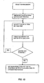
- the method for detection by the microcontroller MC of the information corresponding to the weight of the gate and to the value of the maximum speed that the gate can reach starting from an initial stationary state the motor M of the gate comprises the following steps:
- the time interval between reaching of the end-of-travel of maximum opening and start of closing upon command by the user becomes the time interval in which the gate will remain open automatically during its normal operation.
- the gate slides on the guide set on the ground until it comes to bear upon the end-of-travel sectional element. At this point, the gate closes, and programming terminates and therewith also setting of the operating parameters of the microcontroller MC.
- the parameter corresponding to the length of the travel of the gate is identified only upon completion of the opening and closing cycle in order to prevent that an improper assembly might adversely affect said value during opening of the gate.
- Said value is a function of the number of pulses arriving from the encoder E.
- the encoder E transmits to the microcontroller MC a number of pulses until the motor M stops, and said number of pulses is progressively updated and stored in its nonvolatile memory N.
- the encoder E behaves like a switch, detecting the state of the motor M at any moment, both when the latter is on and when it is off, and continuously transmits a signal to the microcontroller MC.
- the microcontroller MC in turn processes the information received from the encoder E in order to determine the value to be supplied to the PWM circuit for establishing the value of the maximum speed of opening/closing of the gate, in a way inversely proportional to the weight and at the same time, from the number of pulses coming from the encoder E, the length of the travel of the gate for passing from an opening position to a closing position or vice versa.
- the accidental impact is avoided only if said obstacle is intercepted by the infrared rays emitted by the photocell.
- impact of said obstacle with the gate occurs.
- the speed of the gate decreases and the microcontroller MC detects slowing-down of the gate from the pulses that arrive from the encoder E and that have a greater duration than the ones that the encoder E transmits when the gate does not encounter any obstacle on its opening/closing path. Consequently, if the gate is closing, the microcontroller MC intervenes on the MOSFET for controlling the speed of the motor M and, by means of the relay RE, reverses the direction of rotation of the motor M so that the gate will return into its opening position.
- a first advantage is represented by the fact that there do not exist mechanical constraints between the motor reducer and the gate. Hence, in the case where there is damage to the electronic components, in the presence of an obstacle on the opening/closing path the drive wheel skids on the slide guide or else the gate stops in so far as the power of the motor (which is a function of the weight of the gate) is insufficient to draw the gate and push the obstacle.
- a second advantage is represented by the fact that the speed that can be reached by the moving gate during opening/closing is proportional to the weight of the gate itself.
- a third advantage is represented by the fact that, in the case where the gate is initially stationary and receives the command to move, it start moving at a low speed to prevent any skidding between the drive wheel and the guide and subsequently increases its speed.
- a fourth advantage is represented by the fact that in the proximity of the start-of-travel and end-of-travel sectional elements the gate reduces the speed to prevent high-speed impact with said sectional elements. This is a consequence of the fact that the microcontroller MC knows the length of the travel of the gate.
- a fifth advantage is represented by the fact that an automatic adaptation by the microcontroller is provided according to any changes in the operating parameters due to the variations in friction following upon installation of the gate.
Landscapes
- Power-Operated Mechanisms For Wings (AREA)
Claims (25)
- Vorrichtung zum Bewegen gleitender Gates (C), welche auf zwei oder mehr Bodenlaufrädern (F) entlang einer Führungsschiene (3) gleiten, dadurch gekennzeichnet, dass sie in Kombination aufweist:- eine mobile Bewegungseinrichtung, welche derart gestaltet ist, dass sie fest bezüglich des Gates selbst auf einer Gleitschiene gleitet, daran anhaftend während der Versetzung des Gates von der Öffnungsposition in die Schließposition und umgekehrt verbleibt; und- eine elektronische Einrichtung zum Erfassen der Position des Gates, sowohl wenn es sich bewegt als auch wenn es stationär ist, und zum Unterbrechen der Bewegung des Gates im Fall von Hindernissen, welche auf dem Öffnungs-/Schließweg des Gates selbst vorliegen;wobei die mobile Bewegungseinrichtung auf einem Hauptkörper (1) installiert ist, welcher gleitend auf einer vertikalen Führung (2) montiert ist, welche fest an der Vorderseite des Gates (C) befestigt ist, und wobei der Hauptkörper (1) während der normalen Benutzung nach unten entlang der vertikalen Führung (2) versetzbar ist und derart gestaltet ist, dass er in der Position mittels einer absichtlich vorgesehenen Erhebungseinrichtung (4) haltbar ist; wobei der Hauptkörper (1), derart gestaltet ist, dass er in einer erniedrigten Position bezüglich der vertikalen Vorderseite des Gates (C) derart blockierbar ist, dass ein Bodenantriebsrad (R) davon niedriger als das Vorderseitenlaufrad (F) des Gates selbst ist, wodurch das Vorderrad (F) des Gates (C) gleitend von der Führungsschiene (3), entlang derer sich das Gate bewegt, erhebbar ist; wobei der Hauptkörper (1) ein Bodenantriebsrad (R) hat, welches direkt auf der Führungsschiene (3) läuft.
- Vorrichtung nach dem vorhergehenden Anspruch, dadurch gekennzeichnet, dass sie eine mechanische Sicherheitseinrichtung zum schnellen und simultanen Blockieren/Lösen des Gates und der Verriegelung in dem Fall eines Fehlers oder in dem Fall eines Stromausfalls aufweist.
- Vorrichtung nach Anspruch 1, dadurch gekennzeichnet, dass die mobile Bewegungseinrichtung ein Bodenantriebsrad aufweist, welches derart gestaltet ist, dass es durch einen Niederspannungs-Gleichstrommotor bewegbar ist, wobei das Antriebsrad als Alternative zum Bodenlaufrad arbeitet, welches üblicherweise in der Nähe der Vorderseite von gleitenden Gates eines bekannten Typs vorliegt.
- Vorrichtung nach Anspruch 1, dadurch gekennzeichnet, dass die mobile Bewegungseinrichtung einen Elektromotor (M) aufweist, welcher in einer bezüglich des Gates (C) fixierten Schutzeinrichtung enthalten ist, und dass die Versorgung des Motors durch eine Speicherbatterie gewährleistet wird, welche innerhalb der Schützeinrichtung selbst angeordnet ist, wobei die Speicherbatterie mittels eines Induktionssystems wieder aufladbar ist, welches aktivierbar ist, wenn das Gate geschlossen ist.
- Vorrichtung nach Anspruch 1, dadurch gekennzeichnet, dass der Hauptkörper (1) eine im Wesentlichen parallelepipede Gestalt aufweist, welche derart gestaltet ist, dass sie auf der vertikalen Frontkante des gleitenden Gates (C) fixiert ist, wobei in dem Körper (1) zumindest eine Bodenbewegungseinrichtung, eine Versorgungsbatterie oder ein Akkumulator, eine Einrichtung zum Schließen des Gates, eine Einrichtung zum Warnen, dass das Gate sich bewegt, sowie die Steuerelektronik beherbergt ist.
- Vorrichtung nach Anspruch 1, dadurch gekennzeichnet, dass, die Erhebungseinrichtung vorzugsweise vom Keiltyp ist und derart gestaltet ist, dass sie mit einem geneigten Bodenende der vertikalen Führung (2), welche bezüglich des Gates (C) fixiert ist, kooperiert, wodurch sich der Vorderteil des Gates (C) durch Drängen des Keils (4) gegen das geneigte Bodenende der vertikalen Führung (2) erhebt, wohingegen sich das Gate durch Zurückziehen des Keils (4) durch sein eigenes Gewicht erniedrigt.
- Vorrichtung nach dem vorhergehenden Anspruch, dadurch gekennzeichnet, dass der Keil (4) in horizontaler Richtung vorwärts oder rückwärts, d.h. senkrecht zur Führung (2), über eine Schraubeinrichtung versetzbar ist und derart gestaltet ist, dass er auf der Seite des Gates gegenüberliegend der Innenseite, welche einschließbar ist, angebracht ist.
- Vorrichtung nach dem vorhergehenden Anspruch, dadurch gekennzeichnet, dass der Hauptkörper (1) eine Verriegelung, ausgerüstet mit einer Klaue (6), welche auf einem Stift (8), der entlang seiner Länge angebracht ist, ist, und ein Hinterende derart gestaltet hat, dass es mit einer Öffnung oder Unterbrechung (7) der vertikalen Führung (2) interferiert; die Öffnung oder Unterbrechung (7) in einer derartigen Höhe angebracht ist, dass, wenn der Hauptkörper (1) der Vorrichtung vertikal nach oben bezüglich des Gates (C) gleitet und daher ebenfalls bezüglich der Führung (2), welche diesbezüglich fixiert ist, das Hinterende der Klaue erniedrigbar ist, was ein Erheben des Vorderendes der Klaue (6) und eine folgende Entkopplung von dem festen Teil (9), gegen welchen das Gate durch Abstützen darauf schließt, bewirkt.
- Vorrichtung nach einem der Ansprüche 5 bis 8, dadurch gekennzeichnet, dass die Batterie zum Versorgen des Motors, des elektronischen Steuerteils und der Einrichtung zum Warnen, dass das Gate sich bewegt, derart gestaltet ist, dass sie wiederaufladbar ist von der elektrischen Stromversorgung mittels einer Vorderseitenverbindung, welche in einer Position entsprechend dem festen Teil der Verriegelung angeordnet ist, oder sonst durch eine Einrichtung einer Induktionsverbindung oder sonst durch eine Einrichtung von photovoltaischen Zellen.
- Vorrichtung nach Anspruch 1 und 4, dadurch gekennzeichnet, dass die Übertragung der Bewegung zwischen dem Motor (M) und dem Antriebsrad (R) durch eine kinematische Kette mit Antriebsscheiben und einem vorzugsweise gezahnten V-Band (11) mit einem geeigneten Antriebsverhältnis zum Begrenzen der Motorleistungsanforderung auftritt.
- Vorrichtung nach dem vorhergehenden Anspruch, dadurch gekennzeichnet, dass der Motor (M) die entsprechende Antriebsscheibe mittels einer Spiralschrauben-/Helixrad-Verbindung (12) bewegt, um die Übertragung von Bewegung nicht reversibel zu gestalten.
- Vorrichtung nach Anspruch 8, dadurch gekennzeichnet, dass zumindest eine Fotozelle eines bekannten Typs vorgesehen ist, welche ausgestaltet ist zum Erfassen des Vorliegens von Hindernissen entlang des Wegs des Gates (C) während der Versetzungen des Gates selbst; wobei die Fotozelle in einer Position entsprechend dem festen Teil (9) der Verriegelung und des mobilen Teils der Verriegelung selbst, welche bezüglich des Hauptkörpers (1) fixiert ist, angeordnet ist.
- Vorrichtung nach Anspruch 4, dadurch gekennzeichnet, dass die elektronische Steuervorrichtung des elektrischen Motors (M) des Gates aufweist:- einen Mikrocontroller (MC), welcher gestaltet ist, einen geeigneten Betrieb des Motors (M) zu garantieren und welcher in der Lage ist, die Befehle von sowohl dem Benutzer als auch von den Sicherheitsvorrichtungen zu empfangen;- einen Leistungs-MOSFET, welcher zum Steuern der Geschwindigkeit des Motors (M) gestaltet ist;- einen oder mehrere Relaisschaltungen (RE) zum Öffnen/Schließen des Gates, von denen jede derart gestaltet ist, dass sie den MOSFET mit dem Motor (M) verbindet und die Richtung der Drehung des Motors (M) selbst bestimmt, wobei die Relaisschaltungen (RE) mit dem Mikrocontroller (MC) verbunden sind;- einen Codierer (E), der derart gestaltet ist, dass er den Status des Motors (M) erfasst und eine oder mehrere Sequenzen von Impulsen an den Mikrocontroller (MC) überträgt, welche dem Status des Motors (M) entsprechen; wobei der Codierer (E) sowohl mit dem Motor (M) als auch mit dem Mikrocontroller (MC) verbunden ist.
- Vorrichtung nach dem vorhergehenden Anspruch, dadurch gekennzeichnet, dass weiterhin eine Hilfseinrichtung vorgesehen ist zum Anzeigen eines Öffnens/Schließens des Gates, zum Erfassen von Hindernissen auf dem Öffnungs-/Schließweg des Gates und zum befehlsweisen Ausschließen der elektronischen Steuervorrichtung.
- Vorrichtung nach dem vorhergehenden Anspruch, dadurch gekennzeichnet, dass die Hilfseinrichtung aufweist:- zwei weitere MOSFETs, von denen einer entworfen ist zum Antreiben der Verriegelungsvorrichtung und einer entworfen ist zum Antreiben eines LED-Blitzers (vorzugsweise hat der LED-Blitzer eine hohe Helligkeit);- eine Fotozelle, welche zum Emittieren von Infrarotstrahlen gestaltet ist, welcher auf der Gegenplatte (9) angebracht ist;- einen selektiven Empfänger, der gestaltet ist zum Empfangen der Infrarotstrahlen, welcher auf dem Motor lokalisiert ist;- einen Empfänger (beispielsweise Radiofrequenz-, Infrarot-, Ultraschall-Empfänger usw.), der entworfen ist zum Empfangen der Öffnungsbefehle von dem Benutzer über Fernsteuerungen eines bekannten Typs;- einen Mikroschalter, welcher entworfen ist zum Unterbrechen des Betriebs der elektronischen Steuervorrichtung in dem Fall, in dem der Benutzer das Gate mechanisch lösen will;- eine mechanische Lösevorrichtung, welche zum Betätigen des Mikroschalters entworfen ist;- einen ersten Transformator (eine Hälfte) mit Näherungsinduktion;- einen zweiten Transformator (eine Hälfte) der Fotozelle, welcher entworfen ist mit dem ersten Transformator gekoppelt zu sein; und- ein Batterieladegerät.
- Vorrichtung nach Anspruch 13, dadurch gekennzeichnet, dass der Mikrocontroller (MC) aufweist:- eine als "PWM(pulsweiten Modulations-)Schaltung bezeichnete Schaltung, welche zum Steuern der Geschwindigkeit des Motors (M) entworfen ist;- einen nichtflüchtigen Datenspeicher (N) (EEPROM) zum Speichern einer Mehrzahl von Parametern zum geeigneten Betrieb des Gates;- eine Einrichtung zum Messen der Dauer jedes Pulses und zum Zählen der Anzahl von Impulsen (MI);- einen Analog-Digital-Wandler.
- Vorrichtung nach dem vorhergehenden Anspruch, dadurch gekennzeichnet, dass die PWM-Schaltung im Wesentlichen eine Schaltung ist, welche gestaltet ist zum Erzeugen einer Sequenz von Rechteckwellenimpulsen, wobei die Frequenz und das Tastverhältnis davon Parameter sind, welche durch den Mikrocontroller (MC) modifizierbar sind.
- Vorrichtung nach dem vorhergehenden Anspruch, dadurch gekennzeichnet, dass die Betriebsparameter aufweisen: das Gewicht des Geräts, die Zeit, während der das Gate offen bleibt, bevor es wieder geschlossen wird, während eines Zyklus des Öffnens/Schließens; die Länge der Bewegung des Gates zum Gelangen von einer Öffnungsposition in eine Schließposition und umgekehrt, sowie den Fernsteuercode, welcher das Öffnen/Schließen des Gates selbst ermöglicht.
- Vorrichtung nach dem vorhergehenden Anspruch, dadurch gekennzeichnet, dass die Geschwindigkeit des Motors (M) derart gestaltet ist, dass sie durch den Mikrocontroller (MC) regulierbar ist durch Variieren der Zeit, während der die gesamte Versorgungsspannung an die Anschlüsse des Motors (M) angelegt ist.
- Vorrichtung nach dem vorhergehenden Anspruch, dadurch gekennzeichnet, dass die PWM-Schaltung derart gestaltet ist, dass sie die Impulse an den Leistungs-MOSFET sendet, der die Geschwindigkeit des Motors (M) mittels einer absichtlich vorgesehenen Relaisschaltung (RE) steuert, welche die Richtung der Drehung des Motors (M) selbst etabliert.
- Vorrichtung nach dem vorhergehenden Anspruch, dadurch gekennzeichnet, dass zwei Relais (RE) vorgesehen sind: ein Relais zum Öffnen (R1) des Gates und ein Relais zum Schließen (R2) des Gates.
- Vorrichtung nach dem vorhergehenden Anspruch, dadurch gekennzeichnet, dass der Leistungs-MOSFET gestaltet ist zum Arbeiten als ein Schalter, welcher eine Anzahl von Malen pro Sekunde ein- und ausschaltet, sodass die Geschwindigkeit geringer ist als die Geschwindigkeit, welche in kontinuierlicher Leitung erhalten werden würde.
- Vorrichtung nach dem vorhergehenden Anspruch, dadurch gekennzeichnet, dass der Codierer (E) vom magnetischen Typ ist und sein rotierender Teil ein Magnet ist, der auf der Welle des Motors (M) angebracht ist.
- Vorrichtung nach Anspruch 22, dadurch gekennzeichnet, dass der Codierer (E) vom optischen Typ ist und sein rotierender Teil eine perforierte Scheibe ist.
- Vorrichtung nach Anspruch 20 oder Anspruch 21, dadurch gekennzeichnet, dass der Mikrocontroller (MC) bei Anbringung auf dem Gate gestaltet ist zum Durchführen einer automatischen Einstellung der Parameter zum geeigneten Betrieb des Gates mittels eines Zyklus des Öffnens/Schließens des Gates selbst.
Applications Claiming Priority (2)
| Application Number | Priority Date | Filing Date | Title |
|---|---|---|---|
| IT000040A ITRM20070040A1 (it) | 2007-01-26 | 2007-01-26 | Apparato perfezionato per la motorizzazione automatica a controllo elettronico di cancelli scorrevoli |
| PCT/IT2008/000041 WO2008090586A1 (en) | 2007-01-26 | 2008-01-25 | Improved apparatus for electronic-control automatic powering of sliding gates |
Publications (2)
| Publication Number | Publication Date |
|---|---|
| EP2106490A1 EP2106490A1 (de) | 2009-10-07 |
| EP2106490B1 true EP2106490B1 (de) | 2012-09-12 |
Family
ID=39357282
Family Applications (1)
| Application Number | Title | Priority Date | Filing Date |
|---|---|---|---|
| EP08720211A Active EP2106490B1 (de) | 2007-01-26 | 2008-01-25 | Verbesserte vorrichtung zur elektronischen steuerung von schiebetoren |
Country Status (4)
| Country | Link |
|---|---|
| EP (1) | EP2106490B1 (de) |
| AU (1) | AU2008208555A1 (de) |
| IT (1) | ITRM20070040A1 (de) |
| WO (1) | WO2008090586A1 (de) |
Cited By (3)
| Publication number | Priority date | Publication date | Assignee | Title |
|---|---|---|---|---|
| IT202100007079A1 (it) * | 2021-03-24 | 2022-09-24 | Abness Srl Soc Benefit | Barriera scorrevole motorizzata |
| EP4538494A1 (de) * | 2023-10-11 | 2025-04-16 | Picot | Schiebetor mit motorisiertem türblatt |
| FR3154135A1 (fr) * | 2023-10-17 | 2025-04-18 | Yupla | Système d’alimentation d’une motorisation de portail automatique |
Families Citing this family (4)
| Publication number | Priority date | Publication date | Assignee | Title |
|---|---|---|---|---|
| DE102008046538B4 (de) * | 2008-09-10 | 2014-08-07 | Sommer Antriebs- Und Funktechnik Gmbh | Antriebssystem für ein Tor |
| AT511183A1 (de) | 2011-02-28 | 2012-09-15 | Abotic Gmbh | Vorrichtung zum öffnen bzw. schliessen einer tür |
| US12444979B2 (en) | 2019-05-22 | 2025-10-14 | Assa Abloy Entrance Systems Ab | Door operator system with wireless charging capability |
| IT202000010252A1 (it) * | 2020-05-07 | 2021-11-07 | Bottega Del Ferro Di Bianchetti Pier Filippo | Cancello scorrevole motorizzato |
Family Cites Families (4)
| Publication number | Priority date | Publication date | Assignee | Title |
|---|---|---|---|---|
| US4754572A (en) * | 1986-08-13 | 1988-07-05 | M. Bilt Enterprises, Inc. | Motor-operated sliding door assembly |
| US6194851B1 (en) * | 1999-01-27 | 2001-02-27 | Hy-Security Gate, Inc. | Barrier operator system |
| ES2227467T3 (es) * | 2001-04-30 | 2005-04-01 | Christian Chorin | Conjunto autonomo motorizado de arrastre de un porton deslizante. |
| ITRM20030249A1 (it) * | 2003-05-21 | 2004-11-22 | Alberto Gregori | Congegno per la motorizzazione automatica dei cancelli. |
-
2007
- 2007-01-26 IT IT000040A patent/ITRM20070040A1/it unknown
-
2008
- 2008-01-25 AU AU2008208555A patent/AU2008208555A1/en not_active Abandoned
- 2008-01-25 EP EP08720211A patent/EP2106490B1/de active Active
- 2008-01-25 WO PCT/IT2008/000041 patent/WO2008090586A1/en not_active Ceased
Cited By (5)
| Publication number | Priority date | Publication date | Assignee | Title |
|---|---|---|---|---|
| IT202100007079A1 (it) * | 2021-03-24 | 2022-09-24 | Abness Srl Soc Benefit | Barriera scorrevole motorizzata |
| WO2022201059A1 (en) * | 2021-03-24 | 2022-09-29 | Abness Srl Società Benefit | Motorised sliding barrier |
| EP4538494A1 (de) * | 2023-10-11 | 2025-04-16 | Picot | Schiebetor mit motorisiertem türblatt |
| FR3154134A1 (fr) * | 2023-10-11 | 2025-04-18 | Picot | Portail coulissant equipé d’un vantail motorisé |
| FR3154135A1 (fr) * | 2023-10-17 | 2025-04-18 | Yupla | Système d’alimentation d’une motorisation de portail automatique |
Also Published As
| Publication number | Publication date |
|---|---|
| EP2106490A1 (de) | 2009-10-07 |
| AU2008208555A1 (en) | 2008-07-31 |
| WO2008090586A1 (en) | 2008-07-31 |
| ITRM20070040A1 (it) | 2008-07-27 |
Similar Documents
| Publication | Publication Date | Title |
|---|---|---|
| EP2106490B1 (de) | Verbesserte vorrichtung zur elektronischen steuerung von schiebetoren | |
| US7023162B2 (en) | Automatic gate operator | |
| US6246196B1 (en) | Movable barrier operator | |
| EP1828994B1 (de) | Verfahren und einrichtung für automatische systeme, die zum betrieb von beweglichen barrieren ausgelegt sind | |
| WO2002063124A2 (en) | Automatic door control system | |
| US6995533B2 (en) | Controlled torque drive for a barrier operator | |
| CN103628805A (zh) | 一种卷帘门控制装置 | |
| US7183732B2 (en) | Motorized barrier operator system for controlling a stopped, partially open barrier and related methods | |
| CN101784742B (zh) | 用于滑动门或类似物品的线性驱动装置 | |
| US20100089388A1 (en) | Aperture closure apparatus | |
| EP2075399A2 (de) | Sicherheitskontaktleiste für motorisierte Türen | |
| CN203515290U (zh) | 一种卷帘门控制装置 | |
| CN210714285U (zh) | 感应式升降窗 | |
| WO1995008858A2 (en) | Monitoring apparatus | |
| CN220712502U (zh) | 一种智能鸡舍门 | |
| EP1529913A2 (de) | Sicherheitssystem für automatisches Tor | |
| CN209976429U (zh) | 一种由直流卷门机驱动的能遇阻反弹的卷帘门电路 | |
| CN121675730A (zh) | 一种卷帘门自动开关停系统 | |
| HK1080292A (en) | Safety system for automatic gates | |
| JPS6149091A (ja) | シヤツタの開閉制御装置 | |
| JPH05113075A (ja) | 自動車の開閉機構部用制御装置 | |
| JPH0224988B2 (de) |
Legal Events
| Date | Code | Title | Description |
|---|---|---|---|
| PUAI | Public reference made under article 153(3) epc to a published international application that has entered the european phase |
Free format text: ORIGINAL CODE: 0009012 |
|
| 17P | Request for examination filed |
Effective date: 20090811 |
|
| AK | Designated contracting states |
Kind code of ref document: A1 Designated state(s): AT BE BG CH CY CZ DE DK EE ES FI FR GB GR HR HU IE IS IT LI LT LU LV MC MT NL NO PL PT RO SE SI SK TR |
|
| AX | Request for extension of the european patent |
Extension state: AL BA MK RS |
|
| 17Q | First examination report despatched |
Effective date: 20100317 |
|
| GRAP | Despatch of communication of intention to grant a patent |
Free format text: ORIGINAL CODE: EPIDOSNIGR1 |
|
| RIN1 | Information on inventor provided before grant (corrected) |
Inventor name: GREGORI, ALBERTO Inventor name: PITTIGLIO, FERNANDO |
|
| GRAS | Grant fee paid |
Free format text: ORIGINAL CODE: EPIDOSNIGR3 |
|
| GRAA | (expected) grant |
Free format text: ORIGINAL CODE: 0009210 |
|
| AK | Designated contracting states |
Kind code of ref document: B1 Designated state(s): AT BE BG CH CY CZ DE DK EE ES FI FR GB GR HR HU IE IS IT LI LT LU LV MC MT NL NO PL PT RO SE SI SK TR |
|
| AX | Request for extension of the european patent |
Extension state: AL BA MK RS |
|
| REG | Reference to a national code |
Ref country code: GB Ref legal event code: FG4D |
|
| REG | Reference to a national code |
Ref country code: CH Ref legal event code: EP |
|
| REG | Reference to a national code |
Ref country code: AT Ref legal event code: REF Ref document number: 575190 Country of ref document: AT Kind code of ref document: T Effective date: 20120915 |
|
| REG | Reference to a national code |
Ref country code: IE Ref legal event code: FG4D |
|
| REG | Reference to a national code |
Ref country code: DE Ref legal event code: R096 Ref document number: 602008018714 Country of ref document: DE Effective date: 20121108 |
|
| PG25 | Lapsed in a contracting state [announced via postgrant information from national office to epo] |
Ref country code: LT Free format text: LAPSE BECAUSE OF FAILURE TO SUBMIT A TRANSLATION OF THE DESCRIPTION OR TO PAY THE FEE WITHIN THE PRESCRIBED TIME-LIMIT Effective date: 20120912 Ref country code: FI Free format text: LAPSE BECAUSE OF FAILURE TO SUBMIT A TRANSLATION OF THE DESCRIPTION OR TO PAY THE FEE WITHIN THE PRESCRIBED TIME-LIMIT Effective date: 20120912 Ref country code: HR Free format text: LAPSE BECAUSE OF FAILURE TO SUBMIT A TRANSLATION OF THE DESCRIPTION OR TO PAY THE FEE WITHIN THE PRESCRIBED TIME-LIMIT Effective date: 20120912 Ref country code: NO Free format text: LAPSE BECAUSE OF FAILURE TO SUBMIT A TRANSLATION OF THE DESCRIPTION OR TO PAY THE FEE WITHIN THE PRESCRIBED TIME-LIMIT Effective date: 20121212 |
|
| REG | Reference to a national code |
Ref country code: NL Ref legal event code: VDEP Effective date: 20120912 |
|
| REG | Reference to a national code |
Ref country code: AT Ref legal event code: MK05 Ref document number: 575190 Country of ref document: AT Kind code of ref document: T Effective date: 20120912 |
|
| REG | Reference to a national code |
Ref country code: LT Ref legal event code: MG4D Effective date: 20120912 |
|
| PG25 | Lapsed in a contracting state [announced via postgrant information from national office to epo] |
Ref country code: SI Free format text: LAPSE BECAUSE OF FAILURE TO SUBMIT A TRANSLATION OF THE DESCRIPTION OR TO PAY THE FEE WITHIN THE PRESCRIBED TIME-LIMIT Effective date: 20120912 Ref country code: LV Free format text: LAPSE BECAUSE OF FAILURE TO SUBMIT A TRANSLATION OF THE DESCRIPTION OR TO PAY THE FEE WITHIN THE PRESCRIBED TIME-LIMIT Effective date: 20120912 Ref country code: SE Free format text: LAPSE BECAUSE OF FAILURE TO SUBMIT A TRANSLATION OF THE DESCRIPTION OR TO PAY THE FEE WITHIN THE PRESCRIBED TIME-LIMIT Effective date: 20120912 Ref country code: GR Free format text: LAPSE BECAUSE OF FAILURE TO SUBMIT A TRANSLATION OF THE DESCRIPTION OR TO PAY THE FEE WITHIN THE PRESCRIBED TIME-LIMIT Effective date: 20121213 |
|
| PG25 | Lapsed in a contracting state [announced via postgrant information from national office to epo] |
Ref country code: EE Free format text: LAPSE BECAUSE OF FAILURE TO SUBMIT A TRANSLATION OF THE DESCRIPTION OR TO PAY THE FEE WITHIN THE PRESCRIBED TIME-LIMIT Effective date: 20120912 Ref country code: RO Free format text: LAPSE BECAUSE OF FAILURE TO SUBMIT A TRANSLATION OF THE DESCRIPTION OR TO PAY THE FEE WITHIN THE PRESCRIBED TIME-LIMIT Effective date: 20120912 Ref country code: ES Free format text: LAPSE BECAUSE OF FAILURE TO SUBMIT A TRANSLATION OF THE DESCRIPTION OR TO PAY THE FEE WITHIN THE PRESCRIBED TIME-LIMIT Effective date: 20121223 Ref country code: NL Free format text: LAPSE BECAUSE OF FAILURE TO SUBMIT A TRANSLATION OF THE DESCRIPTION OR TO PAY THE FEE WITHIN THE PRESCRIBED TIME-LIMIT Effective date: 20120912 Ref country code: IS Free format text: LAPSE BECAUSE OF FAILURE TO SUBMIT A TRANSLATION OF THE DESCRIPTION OR TO PAY THE FEE WITHIN THE PRESCRIBED TIME-LIMIT Effective date: 20130112 Ref country code: BE Free format text: LAPSE BECAUSE OF FAILURE TO SUBMIT A TRANSLATION OF THE DESCRIPTION OR TO PAY THE FEE WITHIN THE PRESCRIBED TIME-LIMIT Effective date: 20120912 Ref country code: CZ Free format text: LAPSE BECAUSE OF FAILURE TO SUBMIT A TRANSLATION OF THE DESCRIPTION OR TO PAY THE FEE WITHIN THE PRESCRIBED TIME-LIMIT Effective date: 20120912 |
|
| PG25 | Lapsed in a contracting state [announced via postgrant information from national office to epo] |
Ref country code: PL Free format text: LAPSE BECAUSE OF FAILURE TO SUBMIT A TRANSLATION OF THE DESCRIPTION OR TO PAY THE FEE WITHIN THE PRESCRIBED TIME-LIMIT Effective date: 20120912 Ref country code: SK Free format text: LAPSE BECAUSE OF FAILURE TO SUBMIT A TRANSLATION OF THE DESCRIPTION OR TO PAY THE FEE WITHIN THE PRESCRIBED TIME-LIMIT Effective date: 20120912 Ref country code: CY Free format text: LAPSE BECAUSE OF FAILURE TO SUBMIT A TRANSLATION OF THE DESCRIPTION OR TO PAY THE FEE WITHIN THE PRESCRIBED TIME-LIMIT Effective date: 20120912 Ref country code: PT Free format text: LAPSE BECAUSE OF FAILURE TO SUBMIT A TRANSLATION OF THE DESCRIPTION OR TO PAY THE FEE WITHIN THE PRESCRIBED TIME-LIMIT Effective date: 20130114 |
|
| PG25 | Lapsed in a contracting state [announced via postgrant information from national office to epo] |
Ref country code: AT Free format text: LAPSE BECAUSE OF FAILURE TO SUBMIT A TRANSLATION OF THE DESCRIPTION OR TO PAY THE FEE WITHIN THE PRESCRIBED TIME-LIMIT Effective date: 20120912 |
|
| PLBE | No opposition filed within time limit |
Free format text: ORIGINAL CODE: 0009261 |
|
| STAA | Information on the status of an ep patent application or granted ep patent |
Free format text: STATUS: NO OPPOSITION FILED WITHIN TIME LIMIT |
|
| PG25 | Lapsed in a contracting state [announced via postgrant information from national office to epo] |
Ref country code: BG Free format text: LAPSE BECAUSE OF FAILURE TO SUBMIT A TRANSLATION OF THE DESCRIPTION OR TO PAY THE FEE WITHIN THE PRESCRIBED TIME-LIMIT Effective date: 20121212 Ref country code: DK Free format text: LAPSE BECAUSE OF FAILURE TO SUBMIT A TRANSLATION OF THE DESCRIPTION OR TO PAY THE FEE WITHIN THE PRESCRIBED TIME-LIMIT Effective date: 20120912 |
|
| 26N | No opposition filed |
Effective date: 20130613 |
|
| PG25 | Lapsed in a contracting state [announced via postgrant information from national office to epo] |
Ref country code: IT Free format text: LAPSE BECAUSE OF FAILURE TO SUBMIT A TRANSLATION OF THE DESCRIPTION OR TO PAY THE FEE WITHIN THE PRESCRIBED TIME-LIMIT Effective date: 20120912 Ref country code: MC Free format text: LAPSE BECAUSE OF NON-PAYMENT OF DUE FEES Effective date: 20130131 |
|
| REG | Reference to a national code |
Ref country code: CH Ref legal event code: PL |
|
| GBPC | Gb: european patent ceased through non-payment of renewal fee |
Effective date: 20130125 |
|
| REG | Reference to a national code |
Ref country code: DE Ref legal event code: R097 Ref document number: 602008018714 Country of ref document: DE Effective date: 20130613 |
|
| REG | Reference to a national code |
Ref country code: IE Ref legal event code: MM4A |
|
| REG | Reference to a national code |
Ref country code: FR Ref legal event code: ST Effective date: 20130930 |
|
| PG25 | Lapsed in a contracting state [announced via postgrant information from national office to epo] |
Ref country code: DE Free format text: LAPSE BECAUSE OF NON-PAYMENT OF DUE FEES Effective date: 20130801 Ref country code: CH Free format text: LAPSE BECAUSE OF NON-PAYMENT OF DUE FEES Effective date: 20130131 Ref country code: LI Free format text: LAPSE BECAUSE OF NON-PAYMENT OF DUE FEES Effective date: 20130131 |
|
| REG | Reference to a national code |
Ref country code: DE Ref legal event code: R119 Ref document number: 602008018714 Country of ref document: DE Effective date: 20130801 |
|
| PG25 | Lapsed in a contracting state [announced via postgrant information from national office to epo] |
Ref country code: GB Free format text: LAPSE BECAUSE OF NON-PAYMENT OF DUE FEES Effective date: 20130125 Ref country code: FR Free format text: LAPSE BECAUSE OF NON-PAYMENT OF DUE FEES Effective date: 20130131 |
|
| PG25 | Lapsed in a contracting state [announced via postgrant information from national office to epo] |
Ref country code: IE Free format text: LAPSE BECAUSE OF NON-PAYMENT OF DUE FEES Effective date: 20130125 |
|
| PG25 | Lapsed in a contracting state [announced via postgrant information from national office to epo] |
Ref country code: MT Free format text: LAPSE BECAUSE OF FAILURE TO SUBMIT A TRANSLATION OF THE DESCRIPTION OR TO PAY THE FEE WITHIN THE PRESCRIBED TIME-LIMIT Effective date: 20120912 |
|
| PG25 | Lapsed in a contracting state [announced via postgrant information from national office to epo] |
Ref country code: TR Free format text: LAPSE BECAUSE OF FAILURE TO SUBMIT A TRANSLATION OF THE DESCRIPTION OR TO PAY THE FEE WITHIN THE PRESCRIBED TIME-LIMIT Effective date: 20120912 |
|
| PG25 | Lapsed in a contracting state [announced via postgrant information from national office to epo] |
Ref country code: HU Free format text: LAPSE BECAUSE OF FAILURE TO SUBMIT A TRANSLATION OF THE DESCRIPTION OR TO PAY THE FEE WITHIN THE PRESCRIBED TIME-LIMIT; INVALID AB INITIO Effective date: 20080125 Ref country code: LU Free format text: LAPSE BECAUSE OF NON-PAYMENT OF DUE FEES Effective date: 20130125 |