EP2110702B1 - Kompaktes optisches Zoom mit erweiterter Schärfentiefe durch Wellenfront-Kodierung mit Phasenmaske - Google Patents
Kompaktes optisches Zoom mit erweiterter Schärfentiefe durch Wellenfront-Kodierung mit Phasenmaske Download PDFInfo
- Publication number
- EP2110702B1 EP2110702B1 EP08275005A EP08275005A EP2110702B1 EP 2110702 B1 EP2110702 B1 EP 2110702B1 EP 08275005 A EP08275005 A EP 08275005A EP 08275005 A EP08275005 A EP 08275005A EP 2110702 B1 EP2110702 B1 EP 2110702B1
- Authority
- EP
- European Patent Office
- Prior art keywords
- image
- zoom lens
- lens system
- group
- variator
- Prior art date
- Legal status (The legal status is an assumption and is not a legal conclusion. Google has not performed a legal analysis and makes no representation as to the accuracy of the status listed.)
- Not-in-force
Links
- 230000003287 optical effect Effects 0.000 title description 23
- 238000004422 calculation algorithm Methods 0.000 claims description 25
- 239000004033 plastic Substances 0.000 claims description 19
- 230000007246 mechanism Effects 0.000 claims description 16
- 238000003384 imaging method Methods 0.000 claims description 10
- 230000009467 reduction Effects 0.000 claims description 9
- 239000006185 dispersion Substances 0.000 claims description 8
- 230000000694 effects Effects 0.000 claims description 7
- 230000002708 enhancing effect Effects 0.000 claims description 6
- 238000003709 image segmentation Methods 0.000 claims description 6
- 238000005259 measurement Methods 0.000 claims description 5
- 239000011521 glass Substances 0.000 claims description 3
- 238000004458 analytical method Methods 0.000 claims description 2
- 239000002131 composite material Substances 0.000 claims description 2
- 230000001447 compensatory effect Effects 0.000 claims 1
- 238000000034 method Methods 0.000 description 15
- 230000008569 process Effects 0.000 description 7
- 210000001747 pupil Anatomy 0.000 description 6
- 238000012360 testing method Methods 0.000 description 6
- 230000004075 alteration Effects 0.000 description 5
- 238000013461 design Methods 0.000 description 4
- 230000001965 increasing effect Effects 0.000 description 4
- 230000008901 benefit Effects 0.000 description 3
- 238000012545 processing Methods 0.000 description 3
- 239000007787 solid Substances 0.000 description 3
- 238000012546 transfer Methods 0.000 description 3
- 238000013459 approach Methods 0.000 description 2
- 230000008859 change Effects 0.000 description 2
- 230000005526 G1 to G0 transition Effects 0.000 description 1
- 238000012152 algorithmic method Methods 0.000 description 1
- 238000004364 calculation method Methods 0.000 description 1
- 239000006059 cover glass Substances 0.000 description 1
- 230000001419 dependent effect Effects 0.000 description 1
- 238000010586 diagram Methods 0.000 description 1
- 230000007613 environmental effect Effects 0.000 description 1
- 230000010365 information processing Effects 0.000 description 1
- 238000009434 installation Methods 0.000 description 1
- 230000000116 mitigating effect Effects 0.000 description 1
- 238000012986 modification Methods 0.000 description 1
- 230000004048 modification Effects 0.000 description 1
- 239000002991 molded plastic Substances 0.000 description 1
- 238000012805 post-processing Methods 0.000 description 1
- 230000000135 prohibitive effect Effects 0.000 description 1
- 230000005855 radiation Effects 0.000 description 1
- 230000000717 retained effect Effects 0.000 description 1
- 238000005549 size reduction Methods 0.000 description 1
- 230000000007 visual effect Effects 0.000 description 1
Images


Classifications
-
- G—PHYSICS
- G02—OPTICS
- G02B—OPTICAL ELEMENTS, SYSTEMS OR APPARATUS
- G02B27/00—Optical systems or apparatus not provided for by any of the groups G02B1/00 - G02B26/00, G02B30/00
- G02B27/0075—Optical systems or apparatus not provided for by any of the groups G02B1/00 - G02B26/00, G02B30/00 with means for altering, e.g. increasing, the depth of field or depth of focus
-
- G—PHYSICS
- G02—OPTICS
- G02B—OPTICAL ELEMENTS, SYSTEMS OR APPARATUS
- G02B15/00—Optical objectives with means for varying the magnification
- G02B15/14—Optical objectives with means for varying the magnification by axial movement of one or more lenses or groups of lenses relative to the image plane for continuously varying the equivalent focal length of the objective
- G02B15/143—Optical objectives with means for varying the magnification by axial movement of one or more lenses or groups of lenses relative to the image plane for continuously varying the equivalent focal length of the objective having three groups only
- G02B15/1435—Optical objectives with means for varying the magnification by axial movement of one or more lenses or groups of lenses relative to the image plane for continuously varying the equivalent focal length of the objective having three groups only the first group being negative
- G02B15/143503—Optical objectives with means for varying the magnification by axial movement of one or more lenses or groups of lenses relative to the image plane for continuously varying the equivalent focal length of the objective having three groups only the first group being negative arranged -+-
-
- G—PHYSICS
- G02—OPTICS
- G02B—OPTICAL ELEMENTS, SYSTEMS OR APPARATUS
- G02B15/00—Optical objectives with means for varying the magnification
- G02B15/14—Optical objectives with means for varying the magnification by axial movement of one or more lenses or groups of lenses relative to the image plane for continuously varying the equivalent focal length of the objective
- G02B15/143—Optical objectives with means for varying the magnification by axial movement of one or more lenses or groups of lenses relative to the image plane for continuously varying the equivalent focal length of the objective having three groups only
- G02B15/1435—Optical objectives with means for varying the magnification by axial movement of one or more lenses or groups of lenses relative to the image plane for continuously varying the equivalent focal length of the objective having three groups only the first group being negative
- G02B15/143507—Optical objectives with means for varying the magnification by axial movement of one or more lenses or groups of lenses relative to the image plane for continuously varying the equivalent focal length of the objective having three groups only the first group being negative arranged -++
-
- G—PHYSICS
- G02—OPTICS
- G02B—OPTICAL ELEMENTS, SYSTEMS OR APPARATUS
- G02B27/00—Optical systems or apparatus not provided for by any of the groups G02B1/00 - G02B26/00, G02B30/00
- G02B27/42—Diffraction optics, i.e. systems including a diffractive element being designed for providing a diffractive effect
- G02B27/46—Systems using spatial filters
-
- G—PHYSICS
- G02—OPTICS
- G02B—OPTICAL ELEMENTS, SYSTEMS OR APPARATUS
- G02B15/00—Optical objectives with means for varying the magnification
- G02B15/14—Optical objectives with means for varying the magnification by axial movement of one or more lenses or groups of lenses relative to the image plane for continuously varying the equivalent focal length of the objective
- G02B15/16—Optical objectives with means for varying the magnification by axial movement of one or more lenses or groups of lenses relative to the image plane for continuously varying the equivalent focal length of the objective with interdependent non-linearly related movements between one lens or lens group, and another lens or lens group
- G02B15/177—Optical objectives with means for varying the magnification by axial movement of one or more lenses or groups of lenses relative to the image plane for continuously varying the equivalent focal length of the objective with interdependent non-linearly related movements between one lens or lens group, and another lens or lens group having a negative front lens or group of lenses
Definitions
- the invention relates to optical zoom systems, and in particular optical zoom systems that are compact enough to be used on camera modules designed for mobile telephone handsets and similar devices.
- Cameras modules for installation in mobile devices i.e. mobile phone handsets, Portable Digital Assistants (PDAs) and laptop computers
- PDAs Portable Digital Assistants
- laptop computers have to be miniaturised further than those used on compact digital still cameras. They also have to meet more stringent environmental specifications and suffer from severe cost pressure.
- Optical zoom camera modules are in general costly, large and more delicate that their fixed focus and auto-focus counterparts. As such, optical zoom camera modules tend not be used on these kinds of mobile devices, and particularly not on the cheaper or smaller mobile devices.
- a zoom lens is essentially a lens which can be changed in focal length continuously without losing focus.
- a standard compact zoom camera module would typically consist of three groups of lenses as that disclosed in publication US 2003 127584 A1 , two of which are able to move with respect to the other.
- the change of focal length is provided by moving the variator group (generally the middle group of lenses) and the focus is held by changing the position of the compensator group with respect to both the variator group and the image plane.
- the compensator group moves forward and then backward in a parabolic arc to keep the image focussed on the image plane. In doing so, the overall angular magnification of the system varies, changing the effective focal length of the complete zoom lens.
- the position of the variator with respect to the rest of the system in standard 35 mm cameras can be dictated by a mechanical cam, and in compact digital still cameras by digital control of encoded stepper motors or similar. In both these cases the positional accuracy of the compensator to the variator, and to the image plane, is critical. On miniaturisation for use in mobile devices, the further cost of achieving the combined accuracy of the optics, mechanics, actuator and control loop at this scale becomes prohibitive.
- a zoom lens system comprising at least three lens groups and image enhancing means, one of said lens groups comprising the variator group, movable so as to adjust the focal length of the system, and another of said lens groups comprising the compensator lens group, wherein said compensator lens group is arranged to only partially compensate for movement of the variator group, said image enhancing means comprising opto-algorithmic means for extending the depth of field of the lens system, and wherein said image enhancing means further comprises an automatic artefact reduction mechanism, said automatic artefact reduction mechanism comprising: means for estimating a degree of defocus in the obtained image; means for adjusting the reconstruction algorithm to take account of the estimated degree of defocus; and means for performing the adjusted reconstruction algorithm to obtain a restored image.
- Said opto-algorithmic means for extending the depth of field may comprise means for introducing a phase perturbation to obtain a phase-encoded image; means for recording the phase encoded image data; and means for performing a reconstruction algorithm on the recorded phase encoded image data so as to obtain an image in which the effects of the phase perturbation are removed.
- any other opto-algorithmic method may be used and, for example, the encoding need not necessarily be phase encoding, but encoding based on another parameter, for instance easily deconvolved lens aberrations.
- lens group will be understood to include single lenses or groups of two or more lenses.
- the compensator group is in a fixed position and does not move with the variator group.
- the compensator group may move with said variator group via a simple mechanism.
- Said simple mechanism may be a mechanical cam.
- Said zoom lens system may comprise a front fixed lens group which is optically negative and the variator lens group, which may be optically positive.
- Said means for introducing a phase perturbation may be comprised within the variator lens group.
- a stop may be incorporated in said variator lens group.
- the variator lens group may consist of a plastic lens element close to the stop allowing said means for introducing a phase perturbation to be implemented as part of that lens element.
- said means for introducing a phase perturbation may be located on a plate near the stop.
- the variator lens group may comprise two plastic aspheric components and a glass doublet situated on either side of the stop.
- Said front group may comprise a single negative aspheric lens made of a low dispersion plastic.
- Said compensator lens group may comprise two aspheric plastic lens elements wherein a first of these is made of a low dispersion plastic and a second is made of a high dispersion plastic.
- the means for introducing a phase perturbation is a phase mask that yields a focus invariant point-spread function.
- the phase mask is a cubic or petal phase mask.
- phase mask can be an infinite number of different shapes.
- the terms are intended to encompass deviations from the usual shapes as illustrated in the figures, so long as an overall characteristic cubic or petal form is retained in a general sense. That is, changes can be made to the usual cubic and petal shapes that act only to fine tune the effects of the masks rather than to substantially alter their characteristics, and changes of this type are intended to be included in the terms "cubic” and "petal” phase masks in the context of the present description at all points.
- the step of introducing a phase perturbation comprises a wavefront coding step.
- the means for adjusting the reconstruction algorithm may comprise: means for using a measurement of the variator position in determining the reconstruction algorithm, means for measuring an image metric of the obtained image; and means for estimating a new defocus parameter for the image reconstruction algorithm using the image metric.
- the means for estimating a new defocus parameter for the image reconstruction algorithm using the image metric may comprise means for performing an iterative analysis of images reconstructed with various defocus parameters, and means for selecting the defocus parameter that optimises the image metric for obtaining the restored image.
- the image metric is contrast.
- the degree of defocus is chosen as the value that maximises the variance of the image contrast.
- image segmentation means operable to obtain and then combine a restored image for each segmented image feature to form a composite restored image.
- a mobile device comprising imaging means incorporating the zoom lens system of the first aspect of the invention.
- the mobile device is preferably one of a mobile telephone, laptop computer, webcam, digital still camera or camcorder.
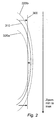
- Figure 1 shows a schematic design for a zoom lens system according to the invention. It shows: a fixed front group 10 which is optically negative; an optically positive variator group 20; a stop 35, which is incorporated in the variator group; a rear group 40, which can either be positive of negative (or neither); and the image plane 50 for the device.
- This arrangement allows for the making of particularly compact optical zoom cameras with only one moving element 20.
- the moving element 20 performs the variator function of a standard two moving group design.
- the arrangement of negative-positive-neg/pos lenses is particularly suitable for compact zoom arrangements. Compensation is performed electronically by way of an image reconstruction algorithm. This may be done by the addition of a wavefront coding (WFC), or other pupil phase mask being placed in the region of the stop 35 which resides in the moving group.
- WFC wavefront coding
- the WFC mask can be place either on a separate plate at the stop 35 or on the surface of lens of group 20 nearest to the stop.
- Figure 2 shows the result of not having a second moving lens group to focus as the variator is moved. It shows the ideal image plane (that is the position of the digital imaging means) 300, and solid arc 310, which shows where the actual image is focussed as the variator group is moved between its two extremes (min and max zoom). Either side of this solid arc is a dotted arc representing the depth of field 320a, 320b.
- the digital imaging means ideal image plane 300
- the image will remain acceptably in focus.
- an automatic artefact reduction mechanism to allow better focus to be obtained at all zoom positions.
- Application of this automatic artefact reduction mechanism essentially has the effect of moving the solid arc 310 towards the image plane 300 as shown by the arrows. Techniques to achieve both increased depth of field and better actual focus are described below.
- WFC wavefront coding
- pupil-plane masks are designed to alter, that is to code, the transmitted incoherent wavefront so that the point-spread function (PSF) is almost constant near the focal plane and is highly extended in comparison with the conventional Airy pattern.
- PSF point-spread function
- the wavefront coded image is distorted and can be accurately restored with digital processing for a wide range of defocus values.
- An optical system 110 comprises lenses and/or other optical elements and a phase encoding means 112 which is near to or in the pupil plane that changes the phase of the radiation that is incident upon it.
- the phase encoding means 112 can take the form of a phase mask. Due to the phase mask, the optical system 110 produces a phase encoded image 114 of an object 116, which is detected by image sensing means 118. The phase encoded image 114 appears blurred when viewed.
- Processing means 120 then applies a reconstruction algorithm to remove the phase encoding to produce a restored image 122, which appears in focus, that is, sharp, when viewed. Because the variation in the point spread function is predetermined by the choice of mask, the reconstruction algorithm can be written to reverse the blurring effects of the phase encoding means 112.
- phase mask for both square and circular apertures.
- Early design of phase masks was carried out in the frequency domain by the use of the ambiguity function (AF).
- AF ambiguity function
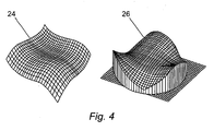
- a cubic phase mask 24 of this type is illustrated in Fig. 2 .
- the strength of the phase mask, ⁇ sets the maximum wavefront deviation and yields the amount of defocus invariance in the decoded image.
- Strehl ratio and Fisher information metrics are solved to be invariant to defocus.
- a technique called Pupil Plane Engineering has been developed by Prasad et al, and is described in S. Prasad, T. Torgersen, V. P. Pauca, R. Plemmons, J. van der Gracht, "Engineering the Pupil Phase to Improve Image Quality," in Proceedings of the SPIE, Vol. 5108 Visual Information Processing XII, edited by Z. Rahman, R. Schowengrdt, and S. Reichenbach (SPIE, Wellingham, WA, 2003), pp. 1-12 .
- This approach generalises the shape of the mask to include higher polynomial orders and is optimised by means of Fisher information metrics.
- ⁇ 1 are normalised co-ordinates and ⁇ and ⁇ are real variables that control the optical path difference (OPD) or amount of coding introduced in the transmitted wavefront of the optical system.
- OPD optical path difference
- ⁇ the OPD introduced by a phase mask.
- the maximum the peak-to-valley OPD is given by 4 ⁇ .
- phase masks which can be manufactured using traditional techniques, also enable aberration mitigation.
- the performance attained by these kinds of phase mask cannot equal that of anti-symmetric masks, but are suitable under modest amounts of aberrations and can be used without digital signal processing.
- Having the WFC, or other phase mask at the stop allows the stop on the moving variator group to be used in conjunction with a stationary compensator group.
- the increase in the maximum allowed defocus W 20 for the system given by WFC allows the zoom system to function with no movement from the compensator group. This is particularly important for compressed systems (i.e. those with overall track length, including the objective lens track, of less than four times the sensor diagonal for a 3x optical zoom function with a wide horizontal field of view greater than 60° (e.g. a track of less than 20 mm for a 3x zoom 1/3" format sensor)).
- the extension to the range of allowed defocus W 20 is due to the variation of f-stop (F/#) with zoom. This is accentuated by the stop being place in the moving, variator group (for a standard system the F/# range is expected to change by a factor of greater than 2 on going form wide to narrow FOV).
- the compensator group does move.
- its movement relative to the variator may, for example, be effected by a simple cam mechanism, rather than the complex arrangements required on conventional lenses to ensure the image is correctly focussed.
- the relatively simple movement proposed serves only to keep the image within a range of de-focus, with the wavefront coding and artefact reduction techniques described herein used to compensate for the lack of accurate focus control.
- a main advantage of this is that such a simple cam control mechanism can be incorporated in the compressed zoom lens arrangements, which would be impossible with conventional compensator zoom control mechanisms.
- the mechanical cam may consist of a single moulded plastic collar with two slots which house pegs attached to the variator and compensator lens groups respectively. Actuation rotates the collar such that the pegs move with respect to each other. The relative position of the two lens groups with respect to each other will thus be controlled to approximately 10 times the tolerance required for a conventional zoom system.
- the position of the cam can be monitored to give a low accuracy location of the variator and thus be used to tune the WFC algorithm appropriately. The uncertainty in position results in an image blur that is compensated for by the WFC process which is tuned to the absolute position of the variator
- the post processing deconvolution kernel is changed on the basis of an automatic artefact reduction mechanism to allow better focus to be obtained at all zoom positions.
- Fig. 4 shows that both the cubic and PPE phase masks are anti-symmetric.
- the OTF of such optical systems is complex and varies significantly with the defocus parameter W 20 .
- the OTF are always real.
- the inventors have realised that the main cause of the image artefacts in a reconstructed phase encoded image is the discrepancy between the phase of the coding OTF and the phase of the decoding filter.
- Fig. 5 shows the PSF after restoration (with a signal magnitude in arbitrary units plotted on the y-axis versus spatial position on the x-axis) of a hybrid optical/digital system including a cubic phase mask for various values of defocus, assuming a phase mask strength of 5 ⁇ .
- Fig. 7 illustrates how the same edge is imaged with a wavefront coded imaging system. It can be seen that the boundary between the light and dark regions is much sharper through the range of defocus values, as expected. However, Fig. 7 .also shows that there are restoration artefacts, in the form of ripples 34, 36, 38, that vary with the defocus parameter W 20 . Therefore, one can interpret the artefacts in the restored image as a defocus signature.
- the top row shows a high contrast circular target 40, together with various sections through the target at zero misfocus, including a horizontal section 42 taken along a horizontal axis, a vertical section 44 taken along a vertical axis, a first diagonal section 46 taken along a diagonal running from the bottom left corner to the top right corner, and a second diagonal section 48 taken along a diagonal running from the top left corner to the bottom right corner, where each of the above axes and diagonals are the lines passing through the centre of the target 40 as illustrated.
- the middle row illustrates the blurred image 50 formed with a cubic phase mask, of the type illustrated in Fig.
- the bottom row illustrates the blurred image 60 formed with a petal phase mask with the same peak-to-valley OPD as the cubic phase mask, of the type illustrated in Fig. 4 that introduces a defocus of 4 ⁇ , and the section 62-68 of the reconstructed image, along the same respective axes or diagonals as the section 42-48 as illustrated above them in the top row.
- the artefacts in the sections 52-58 and 62-68 can be seen as the variations from the ideal sections 42-48, and as discussed, these artefacts arise from the phase and amplitude disparities between the optical convolution and digital deconvolution kernels.
- phase mismatch is a result of the defocus of the camera system, which may be dependent on the position of the object with respect to the focused distance of the camera in object space.
- the decoding kernel may be set for any defocus value if the PSF at that defocus is known.
- removing the artefacts becomes a matter of estimating the defocus present in the image.
- This estimation can be achieved iteratively with various restoration kernels based on a given metric of the degree of artefacts present in the recovered image.
- the artefact removal becomes an optimisation problem for the given metric.
- One possible metric is the image contrast, which will be described in more detail below. Others include but are not limited to sharpness, entropy, energy. The principle for all of these is iterative optimisation of the metric with defocus as the free variable.
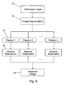
- Image segmentation can also be used to deal with images that comprise several features (or objects) with different degrees of defocus.
- Image segmentation algorithms are well known per se , and so will not be described in detail herein.
- the iterative restoration is applied to each segmented feature or object separately.
- a defocused image 70 corresponds to the phase encoded (blurred) image 14 of the standard set up illustrated in Fig. 1 .
- the defocused image 70 is operated on by an image segmentation algorithm 72 which detects and defines a plurality of features 74 within the image.
- Each of the objects 74 is then operated on by an iterative restoration process 76 before being combined to form a new restored image 78.
- the image segmentation step 72 is optional, and in the event of its omission the defocused image 70 would be directly operated on by the iterative restoration process 74 to render the new restored image 78.
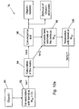
- FIGs. 10a and 10b Examples of the operation of the iterative restoration process 76 are shown in Figs. 10a and 10b .
- the image metric is then calculated (94) a number of times before a convergence test is carried out (96) to determine for which value of W 20 the image metric is optimised.
- convergence depends on the turning point in a plot of a graph of the metric against W 20 , and so the metric must be measured for at least three values of W 20 before convergence can be assumed.
- a counter is set to zero, and a new estimate of the defocus parameter is calculated for the first given value of W 20 .
- a restoration 100 is then carried out with the new kernel, and the counter is incremented so that the metric can be recalculated (94). This cycle repeats until the counter reaches a predetermined limit (which can in one example be three passes), and once the limit is reached a convergence test 96 is carried out which selects the appropriate deconvolution kernel and yields a restored object together with an estimated defocus.
- a predetermined limit which can in one example be three passes
- FIG. 10b A second alternative example of the iterative restoration process 76 is shown in Fig. 10b .
- the image metric is then calculated (80) and then a convergence test is carried out 82 to determine if the image metric is optimised, that is, whether the metric is within a predetermined level of a predetermined threshold. If the convergence test 82 yields a positive result (Y), the object i 74 is restored and an estimation of the defocus is achieved. If the convergence test 82 yields a negative result (N), a new estimate of the defocus parameter W 20 is calculated, 84, which is then used to modify the kernel of the restoration algorithm, 86. This loop is repeated until the convergence test 82 yields a positive result.
- one possible metric is the image contrast.
- One way of measuring the image contrast comprises rescaling the restored image between 0 and 1, and then calculating its variance. This metric takes advantage of the contrast loss in the restored and rescaled image due to the artefacts. It is maximized when the coding and decoding kernels are the same, i.e. when the effective optical transfer function inferred from the restored image features corresponds to that which would be achieved by an in-focus system in the absence of phase coding. This defocus estimation technique has been tested on several reference images. Fig.
- the restored image is free of defocus artefacts when the coding and decoding kernels are equal, and that the variance is maximized in this case, see Fig. 12 , which shows the variance of the restored (and rescaled) image of Lena as a function of the defocus parameter W 20 kernel used in the deconvolution kernels.
- Figure 13 shows an embodiment of the invention where one of the elements adjacent to the stop is made of plastic allowing the imposition of the WFC mask (or other phase mask) on the rear surface of the plastic element 210 which is adjacent to the stop. This is essentially the best location for the phase mask.
- the front group 200 consists of a single negative aspheric lens made of a low dispersion plastic (COC or COP).
- the second group 202 consists of two plastic aspheric components 206, 210 and a glass doublet 212, situated on either side of the stop 211. Note the proximity of the rear surface of plastic element 210 to the stop 211 facilitates the imposition of the WFC or other pupil phase mask. This second group acts as the variator for the zoom system.
- Group three 204 consists of two aspheric plastic elements 213 and 214. To provide a degree of control over chromatic and other aberrations in this compressed system the first of these is made of a low dispersion plastic (COP or COC) and the second is a high dispersion plastic. A cover glass 215 intervenes between the lens and the sensor.
- COP low dispersion plastic
- COC low dispersion plastic
Landscapes
- Physics & Mathematics (AREA)
- General Physics & Mathematics (AREA)
- Optics & Photonics (AREA)
- Lenses (AREA)
- Studio Devices (AREA)
Claims (24)
- Ein Zoomlinsensystem (110), das mindestens drei Linsengruppen (10, 20, 40) und ein Bildverbesserungsmittel beinhaltet, wobei eine der Linsengruppen die Variatorgruppe (20), die bewegbar ist, um die Brennweite des Systems anzupassen, beinhaltet und eine andere der Linsengruppen die Kompensatorlinsengruppe (40) beinhaltet, wobei die Kompensatorlinsengruppe eingerichtet ist, um Bewegung der Variatorgruppe nur teilweise zu kompensieren, wobei das Bildverbesserungsmittel ein opto-algorithmisches Mittel zum Vergrößern der Schärfentiefe beinhaltet; dadurch gekennzeichnet, dass das Bildverbesserungsmittel ferner einen automatischen Artefaktreduktionsmechanismus beinhaltet, wobei der automatische Artefaktreduktionsmechanismus Folgendes beinhaltet:ein Mittel zum Schätzen eines Defokusgrades in einem erhaltenen Bild (116); ein Mittel zum Anpassen des Rekonstruktionsalgorithmus, um den geschätzten Defokusgrad zu berücksichtigen; undein Mittel zum Ausführen des angepassten Rekonstruktionsalgorithmus, um ein wiederhergestelltes Bild zu erhalten.
- Zoomlinsensystem gemäß Anspruch 1, wobei das opto-algorithmische Mittel zum Vergrößern der Schärfentiefe Folgendes beinhaltet: ein Mittel (112) zum Einführen einer Störung, um ein codiertes Bild (114) zu erhalten; ein Mittel (118) zum Erfassen der codierten Bilddaten; und ein Mittel (120) zum Ausführen eines Rekonstruktionsalgorithmus auf die erfassten codierten Bilddaten, um ein Bild (122) zu erhalten, bei dem die Effekte der Störung entfernt sind.
- Zoomlinsensystem gemäß Anspruch 2, wobei das Mittel zum Einführen einer Störung ein Mittel zum Einführen einer Phasenstörung, um ein phasencodiertes Bild zu erhalten, beinhaltet.
- Zoomlinsensystem gemäß Anspruch 3, wobei das Mittel zum Einführen einer Phasenstörung eine Phasenmaske (24, 26) ist, die eine fokusinvariante Punktspreizfunktion ergibt.
- Zoomlinsensystem gemäß Anspruch 4, wobei die Phasenmaske eine kubische (24) oder blattförmige (26) Phasenmaske ist.
- Zoomlinsensystem gemäß einem der Ansprüche 3 bis 5, wobei das Mittel zum Einführen einer Phasenstörung betriebsfähig ist, um einen Wellenfront-Codierungsschritt auszuführen.
- Zoomlinsensystem gemäß einem der Ansprüche 2 bis 6, wobei das Mittel zum Einführen einer Störung in der Variatorlinsengruppe beinhaltet ist.
- Zoomlinsensystem gemäß einem der Ansprüche 2 bis 7, wobei eine Blende (35, 211) in die Variatorlinsengruppe eingebunden ist.
- Zoomlinsensystem gemäß Anspruch 8, wobei die Variatorlinsengruppe aus einem Kunststofflinsenelement nahe der Blende besteht, was ermöglicht, dass das Mittel zum Einführen einer Phasenstörung als Teil jenes Linsenelements implementiert wird.
- Zoomlinsensystem gemäß Anspruch 8, wobei das Mittel zum Einführen einer Phasenstörung auf einer Platte nahe der Blende angeordnet ist.
- Zoomlinsensystem gemäß Anspruch 9, wobei die Variatorlinsengruppe zwei asphärische Kunststoffkomponenten (206, 210) und eine Glasdoppellinse (212), die sich auf beiden Seiten der Blende befinden, beinhalten.
- Zoomlinsensystem gemäß einem der vorhergehenden Ansprüche, wobei die Kompensatorgruppe in einer ortsfesten Position ist und sich nicht mit der Variatorgruppe bewegt.
- Zoomlinsensystem gemäß einem der Ansprüche 1 bis 11, wobei die Kompensatorgruppe eingerichtet ist, um sich mittels eines einfachen Mechanismus mit der Variatorgruppe zu bewegen.
- Zoomlinsensystem gemäß Anspruch 13, wobei der einfache Mechanismus ein Nockenmechanismus ist.
- Zoomlinsensystem gemäß Anspruch 14, wobei der Nockenmechanismus einen Kragen und zwei Betätigungsmittel beinhaltet, je eines zum Betätigen der Variatorlinsengruppe und der Kompensatorlinsengruppe.
- Zoomlinsensystem gemäß einem der vorhergehenden Ansprüche, wobei das System eine vordere ortsfeste Linsengruppe beinhaltet, die optisch negativ ist, und wobei die Variatorlinsengruppe optisch positiv ist.
- Zoomlinsensystem gemäß einem der vorhergehenden Ansprüche, wobei die Kompensatorlinsengruppe zwei asphärische Kunststofflinsenelemente beinhaltet und wobei ein erstes von diesen aus einem Kunststoff mit niedriger Dispersion hergestellt ist und ein zweites aus einem Kunststoff mit hoher Dispersion hergestellt ist.
- Zoomlinsensystem gemäß einem der vorhergehenden Ansprüche, wobei das Mittel zum Anpassen des Rekonstruktionsalgorithmus Folgendes beinhaltet:ein Mittel zum Verwenden einer Messung der Variatorposition beim Bestimmen des Rekonstruktionsalgorithmus,ein Mittel zum Messen einer Bildmetrik des erhaltenen Bildes; undein Mittel zum Schätzen eines neuen Defokusparameters für den Bildrekonstruktionsalgorithmus unter Verwendung der Bildmetrik.
- Zoomlinsensystem gemäß Anspruch 18, wobei das Mittel zum Schätzen eines neuen Defokusparameters für den Bildrekonstruktionsalgorithmus unter Verwendung der Bildmetrik ein Mittel zum Ausführen einer iterativen Analyse von mit verschiedenen Defokusparametern rekonstruierten Bildern und ein Mittel zum Auswählen des Defokusparameters, der die Bildmetrik zum Erhalten des wiederhergestellten Bildes optimiert, beinhaltet.
- Zoomlinsensystem gemäß Anspruch 18 oder 19, wobei die Bildmetrik Kontrast ist.
- Zoomlinsensystem gemäß einem der vorhergehenden Ansprüche, wobei der Defokusgrad als der Wert, der die Abweichung des Bildkontrasts maximiert, gewählt ist.
- Zoomlinsensystem gemäß einem der vorhergehenden Ansprüche, wobei ferner ein Bildsegmentationsmittel bereitgestellt ist, das betriebsfähig ist, um für jedes segmentierte Bildmerkmal ein wiederhergestelltes Bild zu erhalten und dann zusammenzufügen, um ein zusammengesetztes wiederhergestelltes Bild zu bilden.
- Eine mobile Vorrichtung, die ein Bildgebungsmittel beinhaltet, das das Zoomlinsensystem gemäß einem der Ansprüche 1 bis 22 einbindet.
- Mobile Vorrichtung gemäß Anspruch 23, die ein Mobiltelefon, einen Laptop-Computer, eine Webcam, eine digitale Fotokamera oder einen Camcorder beinhaltet.
Priority Applications (2)
| Application Number | Priority Date | Filing Date | Title |
|---|---|---|---|
| EP08275005A EP2110702B1 (de) | 2008-04-16 | 2008-04-16 | Kompaktes optisches Zoom mit erweiterter Schärfentiefe durch Wellenfront-Kodierung mit Phasenmaske |
| US12/423,739 US8203627B2 (en) | 2008-04-16 | 2009-04-14 | Compact optical zoom |
Applications Claiming Priority (1)
| Application Number | Priority Date | Filing Date | Title |
|---|---|---|---|
| EP08275005A EP2110702B1 (de) | 2008-04-16 | 2008-04-16 | Kompaktes optisches Zoom mit erweiterter Schärfentiefe durch Wellenfront-Kodierung mit Phasenmaske |
Publications (2)
| Publication Number | Publication Date |
|---|---|
| EP2110702A1 EP2110702A1 (de) | 2009-10-21 |
| EP2110702B1 true EP2110702B1 (de) | 2012-03-14 |
Family
ID=39601179
Family Applications (1)
| Application Number | Title | Priority Date | Filing Date |
|---|---|---|---|
| EP08275005A Not-in-force EP2110702B1 (de) | 2008-04-16 | 2008-04-16 | Kompaktes optisches Zoom mit erweiterter Schärfentiefe durch Wellenfront-Kodierung mit Phasenmaske |
Country Status (2)
| Country | Link |
|---|---|
| US (1) | US8203627B2 (de) |
| EP (1) | EP2110702B1 (de) |
Families Citing this family (12)
| Publication number | Priority date | Publication date | Assignee | Title |
|---|---|---|---|---|
| EP2104877A4 (de) * | 2006-09-14 | 2010-02-24 | Tessera Tech Hungary Kft | Abbildungssystem mit erhöhter bildqualität und entsprechende verfahren |
| EP2406682B1 (de) * | 2009-03-13 | 2019-11-27 | Ramot at Tel-Aviv University Ltd | Abbildungssystem und abbildungsmethode mit weniger unschärfe |
| TWI424190B (zh) * | 2009-07-17 | 2014-01-21 | Largan Precision Co Ltd | 取像透鏡系統 |
| US20110292273A1 (en) * | 2010-05-27 | 2011-12-01 | Samsung Electro-Mechanics Co., Ltd. | Camera module |
| CN108132529A (zh) * | 2017-03-03 | 2018-06-08 | 中国北方车辆研究所 | 一种基于波前编码的景深变焦光学方法及系统 |
| CN107272158A (zh) * | 2017-07-20 | 2017-10-20 | 瑞声声学科技(苏州)有限公司 | 摄像镜头 |
| WO2020027652A1 (en) | 2018-08-03 | 2020-02-06 | Akkolens International B.V. | Variable focus lens with wavefront encoding phase mask for variable extended depth of field |
| EP3863563A1 (de) | 2018-10-08 | 2021-08-18 | Akkolens International B.V. | Akkommodierende intraokularlinse mit kombination von variablen aberrationen zur erweiterung der tiefenschärfe |
| US10989927B2 (en) * | 2019-09-19 | 2021-04-27 | Facebook Technologies, Llc | Image frame synchronization in a near eye display |
| JP2020204786A (ja) * | 2020-09-17 | 2020-12-24 | マクセル株式会社 | 位相フィルタ、撮像光学系、及び撮像システム |
| CN113703144B (zh) * | 2021-09-26 | 2024-04-26 | 江西凤凰光学科技有限公司 | 一种高像素大靶面镜头 |
| JP2024110363A (ja) * | 2023-02-02 | 2024-08-15 | キヤノン株式会社 | 画像処理装置、撮像装置、画像処理方法、およびプログラム |
Family Cites Families (18)
| Publication number | Priority date | Publication date | Assignee | Title |
|---|---|---|---|---|
| JP2560377B2 (ja) * | 1988-01-26 | 1996-12-04 | キヤノン株式会社 | 防振機能を有した変倍光学系 |
| US6911638B2 (en) * | 1995-02-03 | 2005-06-28 | The Regents Of The University Of Colorado, A Body Corporate | Wavefront coding zoom lens imaging systems |
| JP3275010B2 (ja) * | 1995-02-03 | 2002-04-15 | ザ・リジェンツ・オブ・ザ・ユニバーシティ・オブ・コロラド | 拡大された被写界深度を有する光学システム |
| US7567286B2 (en) * | 1998-02-02 | 2009-07-28 | Canon Kabushiki Kaisha | Image pickup apparatus |
| JP4447845B2 (ja) * | 2003-02-25 | 2010-04-07 | キヤノン株式会社 | カメラ |
| US8254714B2 (en) * | 2003-09-16 | 2012-08-28 | Wake Forest University | Methods and systems for designing electromagnetic wave filters and electromagnetic wave filters designed using same |
| CA2507901A1 (en) * | 2004-05-21 | 2005-11-21 | Imaging Dynamics Company Ltd. | De-noising digital radiological images |
| EP1624672A1 (de) * | 2004-08-07 | 2006-02-08 | STMicroelectronics Limited | Verfahren zur Vermessung von Kantenstärke und Fokus |
| US7830443B2 (en) * | 2004-12-21 | 2010-11-09 | Psion Teklogix Systems Inc. | Dual mode image engine |
| US7412158B2 (en) * | 2005-08-08 | 2008-08-12 | Nokia Corporation | Deeper depth of field for video |
| JP2007248507A (ja) * | 2006-03-13 | 2007-09-27 | Fujinon Corp | ピント情報表示システム |
| JP5239126B2 (ja) * | 2006-04-11 | 2013-07-17 | 株式会社ニコン | 電子カメラ |
| JP2007322560A (ja) * | 2006-05-30 | 2007-12-13 | Kyocera Corp | 撮像装置、並びにその製造装置および製造方法 |
| US8213734B2 (en) * | 2006-07-07 | 2012-07-03 | Sony Ericsson Mobile Communications Ab | Active autofocus window |
| US7612805B2 (en) * | 2006-07-11 | 2009-11-03 | Neal Solomon | Digital imaging system and methods for selective image filtration |
| EP1926047A1 (de) | 2006-11-21 | 2008-05-28 | STMicroelectronics (Research & Development) Limited | Artefaktentfernung von phasenkodierten Bildern |
| US7859588B2 (en) * | 2007-03-09 | 2010-12-28 | Eastman Kodak Company | Method and apparatus for operating a dual lens camera to augment an image |
| US20080285868A1 (en) * | 2007-05-17 | 2008-11-20 | Barinder Singh Rai | Simple Adaptive Wavelet Thresholding |
-
2008
- 2008-04-16 EP EP08275005A patent/EP2110702B1/de not_active Not-in-force
-
2009
- 2009-04-14 US US12/423,739 patent/US8203627B2/en active Active
Also Published As
| Publication number | Publication date |
|---|---|
| US8203627B2 (en) | 2012-06-19 |
| EP2110702A1 (de) | 2009-10-21 |
| US20090262221A1 (en) | 2009-10-22 |
Similar Documents
| Publication | Publication Date | Title |
|---|---|---|
| EP2110702B1 (de) | Kompaktes optisches Zoom mit erweiterter Schärfentiefe durch Wellenfront-Kodierung mit Phasenmaske | |
| US7961969B2 (en) | Artifact removal from phase encoded images | |
| US9142582B2 (en) | Imaging device and imaging system | |
| US7260251B2 (en) | Systems and methods for minimizing aberrating effects in imaging systems | |
| US7593161B2 (en) | Apparatus and method for extended depth of field imaging | |
| US8369642B2 (en) | Artifact removal from phase encoded images | |
| US8044331B2 (en) | Image pickup apparatus and method for manufacturing the same | |
| US20100110233A1 (en) | Imaging Device and Imaging Method | |
| US8462213B2 (en) | Optical system, image pickup apparatus and information code reading device | |
| US20100295973A1 (en) | Determinate and indeterminate optical systems | |
| JP5409588B2 (ja) | 焦点調節方法、焦点調節プログラムおよび撮像装置 | |
| Mao et al. | Fovea Stacking: Imaging with Dynamic Localized Aberration Correction | |
| Harvey et al. | Digital image processing as an integral component of optical design | |
| Bakin | Extended Depth of Field Technology in Camera Systems | |
| Harvey et al. | The principles and roles of hybrid optical/digital codecs in imaging | |
| Chang et al. | Phase coded optics for computational imaging systems | |
| García | Proof-of-concept demonstration of smart optical imaging systems | |
| MONTIEL | Analysis of wavefront coding technology current and future potentialities for optical design future work | |
| HK1088426A1 (zh) | 具有图像增强功能的照相机 | |
| HK1088426B (en) | Camera with image enhancement functions |
Legal Events
| Date | Code | Title | Description |
|---|---|---|---|
| PUAI | Public reference made under article 153(3) epc to a published international application that has entered the european phase |
Free format text: ORIGINAL CODE: 0009012 |
|
| AK | Designated contracting states |
Kind code of ref document: A1 Designated state(s): AT BE BG CH CY CZ DE DK EE ES FI FR GB GR HR HU IE IS IT LI LT LU LV MC MT NL NO PL PT RO SE SI SK TR |
|
| AX | Request for extension of the european patent |
Extension state: AL BA MK RS |
|
| 17P | Request for examination filed |
Effective date: 20100416 |
|
| AKX | Designation fees paid |
Designated state(s): DE FR GB IT |
|
| 17Q | First examination report despatched |
Effective date: 20100708 |
|
| GRAP | Despatch of communication of intention to grant a patent |
Free format text: ORIGINAL CODE: EPIDOSNIGR1 |
|
| GRAS | Grant fee paid |
Free format text: ORIGINAL CODE: EPIDOSNIGR3 |
|
| GRAA | (expected) grant |
Free format text: ORIGINAL CODE: 0009210 |
|
| AK | Designated contracting states |
Kind code of ref document: B1 Designated state(s): DE FR GB IT |
|
| REG | Reference to a national code |
Ref country code: GB Ref legal event code: FG4D |
|
| REG | Reference to a national code |
Ref country code: DE Ref legal event code: R096 Ref document number: 602008014085 Country of ref document: DE Effective date: 20120510 |
|
| PLBE | No opposition filed within time limit |
Free format text: ORIGINAL CODE: 0009261 |
|
| REG | Reference to a national code |
Ref country code: FR Ref legal event code: ST Effective date: 20121228 |
|
| STAA | Information on the status of an ep patent application or granted ep patent |
Free format text: STATUS: NO OPPOSITION FILED WITHIN TIME LIMIT |
|
| 26N | No opposition filed |
Effective date: 20121217 |
|
| GBPC | Gb: european patent ceased through non-payment of renewal fee |
Effective date: 20120614 |
|
| PG25 | Lapsed in a contracting state [announced via postgrant information from national office to epo] |
Ref country code: IT Free format text: LAPSE BECAUSE OF FAILURE TO SUBMIT A TRANSLATION OF THE DESCRIPTION OR TO PAY THE FEE WITHIN THE PRESCRIBED TIME-LIMIT Effective date: 20120314 Ref country code: FR Free format text: LAPSE BECAUSE OF NON-PAYMENT OF DUE FEES Effective date: 20120514 |
|
| REG | Reference to a national code |
Ref country code: DE Ref legal event code: R097 Ref document number: 602008014085 Country of ref document: DE Effective date: 20121217 |
|
| PG25 | Lapsed in a contracting state [announced via postgrant information from national office to epo] |
Ref country code: GB Free format text: LAPSE BECAUSE OF NON-PAYMENT OF DUE FEES Effective date: 20120614 |
|
| PGFP | Annual fee paid to national office [announced via postgrant information from national office to epo] |
Ref country code: DE Payment date: 20140321 Year of fee payment: 7 |
|
| REG | Reference to a national code |
Ref country code: DE Ref legal event code: R119 Ref document number: 602008014085 Country of ref document: DE |
|
| PG25 | Lapsed in a contracting state [announced via postgrant information from national office to epo] |
Ref country code: DE Free format text: LAPSE BECAUSE OF NON-PAYMENT OF DUE FEES Effective date: 20151103 |