EP2111826A1 - Einführvorrichtung mit einer Freisetzeinrichtung zur Freisetzung eines von einem Katheter getragenen Gegenstandes sowie Freisetzeinrichtung einer Einführvorrichtung - Google Patents
Einführvorrichtung mit einer Freisetzeinrichtung zur Freisetzung eines von einem Katheter getragenen Gegenstandes sowie Freisetzeinrichtung einer Einführvorrichtung Download PDFInfo
- Publication number
- EP2111826A1 EP2111826A1 EP09156301A EP09156301A EP2111826A1 EP 2111826 A1 EP2111826 A1 EP 2111826A1 EP 09156301 A EP09156301 A EP 09156301A EP 09156301 A EP09156301 A EP 09156301A EP 2111826 A1 EP2111826 A1 EP 2111826A1
- Authority
- EP
- European Patent Office
- Prior art keywords
- outer shaft
- catheter
- release
- winding
- roller
- Prior art date
- Legal status (The legal status is an assumption and is not a legal conclusion. Google has not performed a legal analysis and makes no representation as to the accuracy of the status listed.)
- Granted
Links
Images




Classifications
-
- A—HUMAN NECESSITIES
- A61—MEDICAL OR VETERINARY SCIENCE; HYGIENE
- A61F—FILTERS IMPLANTABLE INTO BLOOD VESSELS; PROSTHESES; DEVICES PROVIDING PATENCY TO, OR PREVENTING COLLAPSING OF, TUBULAR STRUCTURES OF THE BODY, e.g. STENTS; ORTHOPAEDIC, NURSING OR CONTRACEPTIVE DEVICES; FOMENTATION; TREATMENT OR PROTECTION OF EYES OR EARS; BANDAGES, DRESSINGS OR ABSORBENT PADS; FIRST-AID KITS
- A61F2/00—Filters implantable into blood vessels; Prostheses, i.e. artificial substitutes or replacements for parts of the body; Appliances for connecting them with the body; Devices providing patency to, or preventing collapsing of, tubular structures of the body, e.g. stents
- A61F2/95—Instruments specially adapted for placement or removal of stents or stent-grafts
-
- A—HUMAN NECESSITIES
- A61—MEDICAL OR VETERINARY SCIENCE; HYGIENE
- A61F—FILTERS IMPLANTABLE INTO BLOOD VESSELS; PROSTHESES; DEVICES PROVIDING PATENCY TO, OR PREVENTING COLLAPSING OF, TUBULAR STRUCTURES OF THE BODY, e.g. STENTS; ORTHOPAEDIC, NURSING OR CONTRACEPTIVE DEVICES; FOMENTATION; TREATMENT OR PROTECTION OF EYES OR EARS; BANDAGES, DRESSINGS OR ABSORBENT PADS; FIRST-AID KITS
- A61F2/00—Filters implantable into blood vessels; Prostheses, i.e. artificial substitutes or replacements for parts of the body; Appliances for connecting them with the body; Devices providing patency to, or preventing collapsing of, tubular structures of the body, e.g. stents
- A61F2/95—Instruments specially adapted for placement or removal of stents or stent-grafts
- A61F2/962—Instruments specially adapted for placement or removal of stents or stent-grafts having an outer sleeve
- A61F2/966—Instruments specially adapted for placement or removal of stents or stent-grafts having an outer sleeve with relative longitudinal movement between outer sleeve and prosthesis, e.g. using a push rod
-
- A—HUMAN NECESSITIES
- A61—MEDICAL OR VETERINARY SCIENCE; HYGIENE
- A61F—FILTERS IMPLANTABLE INTO BLOOD VESSELS; PROSTHESES; DEVICES PROVIDING PATENCY TO, OR PREVENTING COLLAPSING OF, TUBULAR STRUCTURES OF THE BODY, e.g. STENTS; ORTHOPAEDIC, NURSING OR CONTRACEPTIVE DEVICES; FOMENTATION; TREATMENT OR PROTECTION OF EYES OR EARS; BANDAGES, DRESSINGS OR ABSORBENT PADS; FIRST-AID KITS
- A61F2/00—Filters implantable into blood vessels; Prostheses, i.e. artificial substitutes or replacements for parts of the body; Appliances for connecting them with the body; Devices providing patency to, or preventing collapsing of, tubular structures of the body, e.g. stents
- A61F2/95—Instruments specially adapted for placement or removal of stents or stent-grafts
- A61F2/962—Instruments specially adapted for placement or removal of stents or stent-grafts having an outer sleeve
- A61F2/97—Instruments specially adapted for placement or removal of stents or stent-grafts having an outer sleeve the outer sleeve being splittable
-
- A—HUMAN NECESSITIES
- A61—MEDICAL OR VETERINARY SCIENCE; HYGIENE
- A61F—FILTERS IMPLANTABLE INTO BLOOD VESSELS; PROSTHESES; DEVICES PROVIDING PATENCY TO, OR PREVENTING COLLAPSING OF, TUBULAR STRUCTURES OF THE BODY, e.g. STENTS; ORTHOPAEDIC, NURSING OR CONTRACEPTIVE DEVICES; FOMENTATION; TREATMENT OR PROTECTION OF EYES OR EARS; BANDAGES, DRESSINGS OR ABSORBENT PADS; FIRST-AID KITS
- A61F2/00—Filters implantable into blood vessels; Prostheses, i.e. artificial substitutes or replacements for parts of the body; Appliances for connecting them with the body; Devices providing patency to, or preventing collapsing of, tubular structures of the body, e.g. stents
- A61F2/95—Instruments specially adapted for placement or removal of stents or stent-grafts
- A61F2/9517—Instruments specially adapted for placement or removal of stents or stent-grafts handle assemblies therefor
Definitions
- the invention relates to an insertion device with a release device for releasing a carried by a catheter object and a release device of an insertion device according to the preambles of the independent claims.
- catheters For the release of articles such as e.g. Stents or in the application of dilation balloons are known to use catheters.
- a field of application relates to e.g. Angioplasty, in which balloon catheters are introduced into blood vessels, inserted into a stenosis and expanded there to eliminate the constriction of the blood vessel.
- a small diameter guidewire protrudes beyond the balloon catheter at the distal end.
- an intravascular prosthetic introducer wherein a catheter engages a tread at its proximal end to facilitate relative displacement between an inner and an outer sheath of the catheter.
- a distal end article such as a stent
- the outer sheath is pulled toward the proximal end. The movement can be uniform by pulling the outer shell into the running device.
- the invention has for its object to provide an improved introducer with a release device for a subject to be released as well as an improved release device of an introducer, which allows for easier and ergonomic handling.
- the invention relates to an insertion device with a release device for releasing an article, in particular a support body, which is supported by a catheter, wherein the catheter has at least one outer shaft, which is relatively displaceable against the object for its release.
- the catheter has, at its proximal end, a winding device which winds a proximal section of the outer shaft in order to produce a relative displacement of the outer shaft.
- the spooling causes the outer shaft to slide away from the distal end of the catheter to the proximal end.
- the sliding movement can be controlled and precise.
- the spooling allows for a compact design of the catheter having a length independent of the length of the object to be released, which may for example be a stent.
- the winding device can relieve the user and at least partially take over the propulsion force for the retraction of the outer shaft during the release of the object. A release can be very controlled and accurate.
- the displacement of the outer shaft can be continuous and uniform. It is also conceivable that a variable displacement speed can be realized manually or automatically, to retire the outer shaft slowly and at the beginning of the release more quickly and towards the end of the release the outer shaft.
- the release device can preferably have a cutting device with which the section of the outer shaft moving toward the proximal end of the catheter can be cut open.
- the cutting device may have at least one cutting edge, which cuts open the outer shaft in the axial direction. By cutting open the outer shaft, the free end of the outer shaft can be taken in the winding device and wound up.
- the catheter can be formed independently of the length of the support body. In the production of catheters for different articles to be released, such as stents, inexpensive identical parts can be used.
- the release device can form a grip part of the catheter. This allows a particularly ergonomic handling of the catheter.
- the release device may form a T-body as an end piece of the catheter.
- the winding device may preferably comprise a roller which is arranged on one side on the catheter. A cut can be produced in the outer shaft and the cut-up skirt surface can be wound up by the winding device.
- the winding device may comprise at least two rollers, preferably arranged symmetrically on the catheter.
- at least two cuts can be produced and the cut-open portion of the outer shaft can be divided into separate surface areas which can each be grasped and wound separately from the winding device. This facilitates the winding, which can be done with less effort.
- the invention is based on a release device of an insertion device for releasing an object, in particular a support body, which is carried by a catheter at its distal end, wherein the catheter has at least one outer shaft which is relatively displaceable against the object for its release.
- a winding device that winds to form a relative displacement of the outer shaft a proximal portion of the outer shaft.
- the spooling causes the outer shaft to slide away from the distal end of the catheter to the proximal end.
- the sliding movement can be controlled and precise.
- a release of the article can be very controlled and accurate, since the small dimension of the handling part advantageously allows optimal handling.
- the displacement of the outer shaft can be continuous and uniform. It is also conceivable that a variable displacement speed can be realized manually or automatically in order to withdraw the outer shaft slowly and, for example, at the beginning of the release for a more precise positioning, and to retract the outer shaft more quickly towards the end of the release.
- the winding device can be conveniently connected to a conventional catheter.
- a cutting device can be coupled with the winding device, with which the section of the outer shaft moving toward the proximal end of the catheter can be cut open, when the outer shaft moves to release the object at the distal end of the catheter to the proximal end.
- At least one roller may be provided in the winding device, to which the outer shaft can be wound at least in regions.
- the outer shaft can be moved at a constant speed of revolution at a variable speed.
- An improved handling results when the at least one roller can be locked by a lock. This allows a defined start of the release and a good control of the movement of the outer shaft, which can also be interrupted controlled.
- the winding device for winding can be conveniently coupled to a spring element so that by the spring force winding and / or movement of the External support can be supported. This allows a particularly simple and controlled handling of the winding device.
- the winding device for winding the outer shaft can be driven manually, z. B. with a crank element.
- the winding device may alternatively or in addition to winding the outer shaft comprise an electric drive.
- the winding of the outer shaft can be done without the use of force of the user.
- the winding device may have an actuating element which releases the at least one roller for carrying out a rotational movement in a first position and blocks the at least one roller in a further position.
- an actuating element which releases the at least one roller for carrying out a rotational movement in a first position and blocks the at least one roller in a further position.
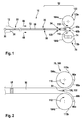
- Fig. 1 shows a first preferred embodiment of the invention with a preferred first introducer 10 with a preferred release means 70 for releasing an article 12, in particular a support body carried at a distal end 22 of a catheter 20, the catheter 20 having at least one outer shaft 50, which is relatively displaceable against the article 12 for release in a draw direction 68.
- the catheter 20 has at its proximal end 24 a winding device 100 which winds to form the relative displacement of the outer shaft 50 a proximal portion 52 of the outer shaft 50.
- the proximal portion 52 of the outer shaft 50 corresponds to the length of the article 12, e.g. may be a self-expanding stent.
- Proximal and distal refer to the position of the user, the proximal end 24 is adjacent to the user while the distal end 22 is remote from the user.
- the outer shaft 50 is arranged around an inner shaft 28, wherein at the distal end 22 of the catheter 20, a tip 30 for guiding the catheter 20 via an insertion wire (Guide Wire) is provided in a conventional manner, wherein the article 12 surrounds the inner shaft 28 and for insertion into, for example, a blood vessel within the outer shaft 50.
- a tip 30 for guiding the catheter 20 via an insertion wire Guide Wire
- the winding device 100 in this exemplary embodiment comprises two rollers 104a, 104b which are arranged symmetrically with respect to the catheter 20 or outer shaft 50 and which can be driven by a drive (not shown), e.g. a crank or an electric motor.
- a drive e.g. a crank or an electric motor.
- the release device 70 comprises, in addition to the winding device 100, a cutting device 120 with at least one cutting edge 122, with which the section 52 of the outer shaft 50 moved toward the proximal end 24 of the catheter 20 can be cut along the longitudinal extension 72 of the outer shaft 50.
- a symmetrical separation of the outer shaft 50 into two parts 60a, 60b is expedient.
- the outer shaft 50 may be cut open at the proximal end of the catheter 20 and its ends secured to the rollers 104a, 104b.
- the rollers 104a, 104b are rotated, the parts 60a, 60b are laid down on a lateral surface 113a (roller 104a) and 113b (roller 104b) of the rollers 104a, 104b and fastened with the ends 66a, 66b, as in the detail of FIGS Fig. 2 can be seen more clearly.
- the rollers 104a, 104b are rotated in opposite directions of rotation 110, 112, the roller 104a e.g. in the counterclockwise direction and the roller 104b in a clockwise direction.
- the rotation can be done with a drive 74, e.g. a manually operable crank, or even electrically (not shown).
- the drive 74 is actuated on the roller 104b and set in rotation, this can be achieved by a favorable embodiment of the winding device 100 (FIG. Fig. 4a, 4b ) the other roller 104a are moved with.
- a toothed wheel 108a, 108b is arranged on each roller 104a, 104b at one end.
- the gears 108a, 108b mesh with each other, so that the movement of a roller 104b, for example, the other role, eg 104a, entrains and allows symmetrical winding ( Fig. 4a, 4b ).
- FIG. 12 shows a variant of the invention in which a plurality of cuts are not made in the outer shaft 50 but only a one-sided cut 54 is made from a proximal free end 66 of the outer shaft 50 to a stop 58 along the longitudinal extent 72 of the catheter 20.
- the winding device (not shown) then preferably has only a single role for winding the outer shaft 50, as in the embodiment in Fig. 7a, 7b is explained in more detail.
- Fig. 5 shows a preferred release device 70 with two rollers 104a, 104b in a housing 86 in plan view
- Fig. 6 shows an end body 80 of the catheter 20 in side view, on which the housing 86 with the release device 70 is arranged (housing and winding device in the side view in FIG Fig. 6 not shown) can be.
- the end body 80 may also be integrated into the housing 86 of the release device 70
- the rollers 104a, 104b are symmetrical to each other and rotate in opposite directions.
- the rollers 104a, 104b may be fixed or released with a detent 118 disposed on one of the rollers 104b.
- the inner shaft 28 of the catheter 20 (FIG. Fig. 1 ) can eg by means of a metal shaft 88 ( Fig. 6 ; Fig. 8a, 8b ) are fixed in the housing 86.
- a kink guard 26 is attached to the catheter 20, which encases the catheter 20.
- a port 82 e.g. in the form of a so-called Luer lock, serves for the usual flushing of a space between inner shaft 28 and outer shaft 50, and arranged at the free end port 84, which may also be formed as a Luer lock, serves for introducing a guide wire (Guide Wire) and the Rinse this area.
- a guide wire Guide Wire
- two symmetrically arranged blades 122 are arranged on a lug 124 of the end body 80, which cut the outer shaft 50 from the inside when retracted. It would also be conceivable to arrange the outer shaft 50 with external cutting edges (not shown) longitudinally.
- Distal and proximal seals 80 and 96 are respectively disposed on the end body 80 to seal the space between the inner shaft 28 and the outer shaft 50, and the metal shaft 88 and the end body 80 and the outer shaft 50, respectively.
- the already partially slotted outer shaft 50 is attached to the outer surfaces 113a, 113b of the rollers 104a, 104b to be wound on them, as in FIGS Fig. 1 and 2 was hinted at.
- the outer shaft 50 is wound up and thus automatically retracted to the proximal end 24 of the catheter 20.
- the article 12 (FIG. Fig. 1 ), such as a self-expanding stent, released.
- Fig. 7a, 7b schematically illustrate further preferred embodiments of an insertion device 10 according to the invention with a release device 70, which comprises a winding device 100, which has only one roller 102 and comprises a one-sided cutting device, as shown in FIG Fig. 3 is shown schematically.
- the roller 102 is arranged on one side of the catheter 20.
- the release device 70 is integrated into an end body 80 of the catheter 20 and forms a handle portion of the catheter 20 with a grip portion 94 which the user can hold in his hand.
- the roller 102 can be rotated either clockwise or counterclockwise with the user only allowed to rotate in one direction and the opposite direction locked.
- the catheter 20 is externally provided with a kink guard 26, protrudes into the end body 80, and may also be secured to the end body 80 with a metal stem as described above.
- Fig. 7a shows an embodiment in which the roller 102 of the winding device 100 is arranged upright, so that the roller 102 with its circular area is parallel to the catheter 20.
- Fig. 7b an alternative embodiment is shown, in which the catheter 20 is arranged tangentially to the roller 102.
- the existing cutting device is not shown explicitly.
- the roller 102 can be fixed or released, which is indicated by a double arrow.
- the roller 102 is disposed distal to the handle portion 94 of the end body 80.
- the roller 102 rotate, for example, with the thumb, so that a one-handed operation of the release device 70 and the winding device 100 of the insertion device 10 is possible. Stopping the slicing may be accomplished with a stop member 58 (FIG. Fig. 1, 2 . 3 ), or by allowing only a limited number of revolutions of roll 102.
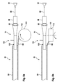
- Fig. 8a and 8b show a further preferred embodiment of the invention with a designed as T-body end body 80, wherein the roller 102 of the winding device 100 tangentially ( Fig. 8a ) or parallel next to the catheter 20 and the end body 80 (FIG. Fig. 8b ) is arranged.
- the rollers 102, 104a, 104b in the above-described embodiments of the winding device 100 may have a cylindrical lateral surface 113 or may also have a tapered shape, as in FIG Fig. 9 is shown.
- the roller 102, 104a, 104b has a larger diameter of the lateral surface 113 than at its opposite axial end 116. This results in that the parts 60, 60a, 60b of the outer shaft 50 at a constant rotational speed of the roller 102, 104a, 104b are wound at different speeds, depending on the axial height at which the parts 60, 60a, 60b are deposited.
- the Figures 10a and 10b show a detail of an advantageous winding device 100, in which the roller 102, 104a, 104b can be mechanically or electrically rotated with a triggering mechanism 130.
- the triggering mechanism extends along a central axis 140 of the roller 102, 104a, 104b.
- An actuating element 132 can be moved downward against a spring force of a spring element 134 designed as an axial spring, for example.
- a counter element 138 is moved out of a brake 136 and the axle 140 is thus released.
- the brake 136 may include brake shoes engaged by the mating member 138 when the roller 102, 104a, 104b is blocked.
- the axle 140 is coupled to a spring element 106 designed as a torsion spring, which can set the axle 140 and thus the roller 102, 104a, 104b in a rotational movement when the counter element 138 is decoupled from the brake 136.
- a spring element 106 designed as a torsion spring, which can set the axle 140 and thus the roller 102, 104a, 104b in a rotational movement when the counter element 138 is decoupled from the brake 136.
- the spring element 106 may also be provided an electric drive.
- the coil 102, 104a, 104b can be operated by the push of a button and offers the possibility of realizing different winding speeds. Stopping the slicing can be achieved, for example, by allowing only a limited number of revolutions of the rollers 102, 104a, 104b and / or limited movement of the spring element 106.
- the slicing and winding of the outer shaft 50 allows for the provision of a short handling portion of the catheter 20. This advantageously results in easier handling and shortened displacement of the catheter 20 over the guidewire (guide wire).
- the simplification of the release process in particular via a simple button operation of the release device, allows a more accurate and homogeneous positioning of the article, e.g. a stent in the blood vessel.
Landscapes
- Health & Medical Sciences (AREA)
- Engineering & Computer Science (AREA)
- Biomedical Technology (AREA)
- Cardiology (AREA)
- Oral & Maxillofacial Surgery (AREA)
- Transplantation (AREA)
- Heart & Thoracic Surgery (AREA)
- Vascular Medicine (AREA)
- Life Sciences & Earth Sciences (AREA)
- Animal Behavior & Ethology (AREA)
- General Health & Medical Sciences (AREA)
- Public Health (AREA)
- Veterinary Medicine (AREA)
- Media Introduction/Drainage Providing Device (AREA)
Abstract
Description
- Die Erfindung betrifft eine Einführvorrichtung mit einer Freisetzeinrichtung zur Freisetzung eines von einem Katheter getragenen Gegenstandes sowie eine Freisetzeinrichtung einer Einführvorrichtung nach den Oberbegriffen der unabhängigen Ansprüche.
- Zur Freisetzung von Gegenständen wie z.B. Stents oder bei der Anwendung von Dilatationsballons kommen bekanntermaßen Katheter zum Einsatz. Ein Anwendungsgebiet betrifft z.B. die Angioplastie, bei der Ballonkatheter in Blutgefäße eingeführt, bis zu einer Stenose eingeschoben und dort aufgeweitet werden, um die Verengung des Blutgefäßes zu beseitigen. Üblicherweise ragt am distalen Ende ein Führungsdraht mit kleinem Durchmesser über den Ballonkatheter hinaus.
- Bekannt ist aus der
DE 600 11 355 T2 eine Einführvorrichtung für eine intravaskuläre Prothese bei der ein Katheter an seinem proximalen Ende in eine Laufvorrichtung eingreift, die eine relative Verschiebung zwischen einer inneren und einer äußeren Hülle des Katheters erleichtert. Zum Freisetzen eines am distalen Ende angeordneten Gegenstands, wie etwa einem Stent, wird die äußere Hülle zum proximalen Ende gezogen. Die Bewegung kann gleichförmig erfolgen, indem die äußere Hülle in die Laufvorrichtung hineingezogen wird. - Auch aus der beispielhaft genannten
EP 1 447 058 A1 , derUS 6 866 669 B2 und derEP 747 021 A2 - Bei den vorbekannten Lösungen besteht eine Abhängigkeit zwischen der Gesamtlänge des Katheters und der Stentlänge. Je länger der Stent ist, desto länger ist die Gesamtlänge des Katheters. So ergibt sich beispielsweise eine Gesamtlänge eines Katheters mit einer Stentlänge von 200 mm, die um mindestens 180 mm länger ist als die eines Katheters mit 20 mm Stentlänge. Für einen Anwender, z.B. den Arzt, der den Katheter einführt, bedeutet dies den Einsatz eines längeren Führungsdrahts (Guide Wire) und eine entsprechend komplizierte und unergonomische Handhabung.
- Der Erfindung liegt die Aufgabe zugrunde, eine verbesserte Einführvorrichtung mit einer Freisetzeinrichtung für einen freizusetzenden Gegenstand sowie eine verbesserte Freisetzeinrichtung einer Einführvorrichtung zu schaffen, die eine leichtere und ergonomische Handhabung ermöglicht.
- Die Aufgabe wird erfindungsgemäß durch die Merkmale der unabhängigen Ansprüche gelöst. Günstige Ausgestaltungen und Vorteile der Erfindung ergeben sich aus den weiteren Ansprüchen und der Beschreibung.
- Die Erfindung geht aus von einer Einführvorrichtung mit einer Freisetzeinrichtung zur Freisetzung eines Gegenstands, insbesondere eines Stützkörpers, der von einem Katheter getragen ist, wobei der Katheter wenigstens einen Außenschaft aufweist, welcher gegen den Gegenstand zu dessen Freisetzung relativ verschieblich ist.
- Es wird vorgeschlagen, dass der Katheter an seinem proximalen Ende eine Aufspuleinrichtung aufweist, die zur Erzeugung einer relativen Verschiebung des Außenschafts einen proximalen Abschnitt des Außenschafts aufspult. Das Aufspulen versetzt den Außenschaft in eine Gleitbewegung weg vom distalen Ende des Katheters zum proximalen Ende. Die Gleitbewegung kann kontrolliert und präzise erfolgen. Das Aufspulen ermöglicht eine kompakte Ausführung des Katheters mit einer Länge unabhängig von der Länge des freizusetzenden Gegenstands, der beispielsweise ein Stent sein kann. Ebenso kann die Aufspuleinrichtung den Anwender entlasten und die Vortriebskraft für das Zurückziehen des Außenschafts bei der Freisetzung des Gegenstands wenigstens teilweise übernehmen. Eine Freisetzung kann sehr kontrolliert und exakt erfolgen. Bei einer Motorisierung der Aufspuleinrichtung kann das Verschieben des Außenschafts kontinuierlich und gleichmäßig erfolgen. Ebenso ist denkbar, dass eine variable Verschiebegeschwindigkeit manuell oder automatisiert verwirklicht werden kann, um etwa zu Beginn des Freisetzens den Außenschaft langsam und gegen Ende des Freisetzens den Außenschaft schneller zurückzuziehen.
- Bevorzugt kann die Freisetzeinrichtung eine Schneidvorrichtung aufweisen, mit der der zum proximalen Ende des Katheters bewegte Abschnitt des Außenschafts aufschneidbar ist. Vorzugsweise kann die Schneidvorrichtung wenigstens eine Schneide aufweisen, welche den Außenschaft in axialer Richtung aufschneidet. Durch das Aufschneiden des Außenschafts kann das freie Ende des Außenschafts in der Aufspuleinrichtung gefasst und aufgespult werden. Dadurch kann vermieden werden, dass bei Stützkörpern wie etwa Stents mit großen Längenausdehnungen der Katheter länger ausgeführt werden muss als bei kürzeren Stützkörpern, um eine sichere Freisetzung des Stützkörpers zu gewährleisten. Der Katheter kann unabhängig von der Länge des Stützkörpers ausgebildet werden. Bei der Herstellung von Kathetern für unterschiedliche freizusetzende Gegenstände wie etwa Stents können preiswerte Gleichteile verwendet werden.
- Vorteilhaft kann die Freisetzeinrichtung ein Griffteil des Katheters bilden. Dies erlaubt eine besonders ergonomische Handhabung des Katheters. Ebenso kann die Freisetzeinrichtung einen T-Körper als Endstück des Katheters bilden.
- Die Aufspuleinrichtung kann vorzugsweise eine Rolle umfassen, die einseitig am Katheter angeordnet ist. Es kann ein Schnitt im Außenschaft erzeugt werden und die aufgeschnittene Schaftmantelfläche von der Aufspuleinrichtung aufgespult werden.
- Alternativ kann die Aufspuleinrichtung wenigstens zwei am Katheter, vorzugsweise symmetrisch angeordnete Rollen umfassen. Hier können wenigstens zwei Schnitte erzeugt werden und der aufgeschnittene Abschnitt des Außenschafts in getrennte Flächenbereiche geteilt werden, die jeweils separat von der Aufspuleinrichtung gefasst und aufgespult werden können. Dies erleichtert das Aufspulen, das mit weniger Kraftaufwand erfolgen kann.
- Weiterhin geht die Erfindung aus von einer Freisetzeinrichtung einer Einführvorrichtung zur Freisetzung eines Gegenstands, insbesondere eines Stützkörpers, der von einem Katheter an dessen distalem Ende getragen ist, wobei der Katheter wenigstens einen Außenschaft aufweist, welcher gegen den Gegenstand zu dessen Freisetzung relativ verschieblich ist.
- Es wird eine vorgeschlagen, eine Aufspuleinrichtung vorzusehen, die zur Erzeugung einer relativen Verschiebung des Außenschafts einen proximalen Abschnitt des Außenschafts aufspult. Das Aufspulen versetzt den Außenschaft in eine Gleitbewegung weg vom distalen Ende des Katheters zum proximalen Ende. Die Gleitbewegung kann kontrolliert und präzise erfolgen. Eine Freisetzung des Gegenstands kann sehr kontrolliert und exakt erfolgen, da die kleine Dimension des Handhabungsteils vorteilhaft eine optimale Handhabung erlaubt. Bei einer Motorisierung der Aufspuleinrichtung kann das Verschieben des Außenschafts kontinuierlich und gleichmäßig erfolgen. Ebenso ist denkbar, dass eine variable Verschiebegeschwindigkeit manuell oder automatisiert verwirklicht werden kann, um etwa zu Beginn des Freisetzens zum genauerem Positionieren den Außenschaft langsam und gegen Ende des Freisetzens den Außenschaft schneller zurückzuziehen. Die Aufspuleinrichtung kann günstigerweise an einen üblichen Katheter angeschlossen werden.
- Vorzugsweise kann mit der Aufspuleinrichtung eine Schneidvorrichtung koppelbar sein, mit der der zum proximalen Ende des Katheters bewegte Abschnitt des Außenschafts aufschneidbar ist, wenn sich der Außenschaft zum Freisetzen des Gegenstands am distalen Ende des Katheters zum proximalen Ende bewegt.
- Wenigstens eine Rolle kann in der Aufspuleinrichtung vorgesehen sein, auf die der Außenschaft wenigstens bereichsweise aufspulbar ist.
- Kann die wenigstens eine Rolle an einem axialen Ende einen kleineren Durchmesser aufweisen als am gegenüberliegenden axialen Ende, kann der Außenschaft bei konstanter Umdrehungsgeschwindigkeit mit veränderlicher Geschwindigkeit bewegt werden.
- Eine verbesserte Handhabung ergibt sich, wenn die wenigstens eine Rolle durch eine Arretierung arretierbar sein kann. Dies ermöglicht einen definierten Beginn der Freisetzung sowie eine gute Kontrolle der Bewegung des Außenschafts, die auch kontrolliert unterbrochen werden kann.
- Die Aufspuleinrichtung zum Aufwickeln kann günstigerweise mit einen Federelement so gekoppelt sein, dass durch die Federkraft das Aufspulen und/oder die Bewegung des Außenschafts unterstützt werden kann. Dies ermöglicht eine besonders einfache und kontrollierte Handhabung der Aufspuleinrichtung.
- Die Aufspuleinrichtung zum Aufspulen des Außenschafts kann händisch antreibbar sein, z. B. mit einem Kurbelelement.
- Die Aufspuleinrichtung kann alternativ oder zusätzlich zum Aufspulen des Außenschafts einen elektrischen Antrieb umfassen. Damit kann das Aufspulen des Außenschafts ohne Krafteinsatz des Anwenders erfolgen.
- Die Aufspuleinrichtung kann ein Betätigungselement aufweisen, das in einer ersten Stellung die wenigstens eine Rolle zur Ausführung einer Drehbewegung freigibt und in einer weiteren Stellung die wenigstens eine Rolle blockiert. Vorteilhafterweise kann so eine definierte und gesteuerte Bewegung des Außenschafts erreicht werden.
- Die Erfindung ist nachfolgend beispielhaft, anhand von in Zeichnungen dargestellten Ausführungsbeispielen, näher erläutert. Es zeigen in schematischer Darstellung:
- Fig. 1
- eine erste bevorzugte Ausgestaltung der Erfindung mit einer Aufspuleinrichtung zum Aufspulen eines aufgeschnittenen Außenschafts zur Freisetzung eines Stents an einem distalen Ende eines Katheters;
- Fig. 2
- ein Detail der Ausgestaltung der
Fig. 1 ; - Fig. 3
- eine weitere bevorzugte Ausgestaltung der Erfindung mit einem einseitig aufgeschnittenen Außenschaft;
- Fig. 4a, 4b
- Detailansichten zweier miteinander zusammenwirkenden Rollen einer bevorzugten Aufspuleinrichtung;
- Fig. 5
- eine Draufsicht auf eine Einführvorrichtung mit einer bevorzugten Aufspuleinrichtung;
- Fig. 6
- eine Seitenansicht der bevorzugten Einführvorrichtung in
Fig. 5 ohne Gehäuse und Aufspuleinrichtung; - Fig. 7a, 7b
- alternative Ausgestaltungen einer bevorzugten Einführvorrichtung mit unterschiedlich zu einem Katheter orientierten Rollen;
- Fig. 8a, 8b
- weitere alternative Ausgestaltungen einer bevorzugten Einführvorrichtung mit unterschiedlich zu einem Katheter orientierten Rollen; und
- Fig. 9
- eine bevorzugte Ausgestaltung einer Rolle einer Aufspuleinrichtung;
- Fig. 10a, 10b
- einen bevorzugten Auslösemechanismus einer Aufspuleinrichtung mit einer Rolle (
Fig. 10a ) mit einem Detail des Auslösemechanismus (Fig. 10b ); - In den Figuren sind funktionell gleiche oder gleich wirkende Elemente jeweils mit denselben Bezugszeichen beziffert. Die Figuren sind schematische Darstellungen der Erfindung. Sie bilden nicht spezifische Parameter der Erfindung ab. Weiterhin geben die Figuren lediglich typischen Ausgestaltungen der Erfindung wieder und sollen die Erfindung nicht auf die dargestellten Ausgestaltungen beschränken.
- Zur Vermeidung unnötiger Wiederholungen wird bei nicht näher beschriebenen Elementen in einer Figur auf die jeweilige Beschreibung der Elemente in vorstehenden Figuren verwiesen.
-
Fig. 1 zeigt eine erste bevorzugte Ausgestaltung der Erfindung mit einer bevorzugten ersten Einführvorrichtung 10 mit einer bevorzugten Freisetzeinrichtung 70 zur Freisetzung eines Gegenstands 12, insbesondere eines Stützkörpers, der an einem distalen Ende 22 eines Katheters 20 getragen ist, wobei der Katheter 20 wenigstens einen Außenschaft 50 aufweist, welcher gegen den Gegenstand 12 zu dessen Freisetzung in einer Ziehrichtung 68 relativ verschieblich ist. - Der Katheter 20 weist an seinem proximalen Ende 24 eine Aufspuleinrichtung 100 auf, die zur Erzeugung der relativen Verschiebung des Außenschafts 50 einen proximalen Abschnitt 52 des Außenschafts 50 aufspult. Der proximale Abschnitt 52 des Außenschafts 50 korrespondiert mit der Länge des Gegenstands 12, der z.B. ein selbstexpandierender Stent sein kann. Proximal und distal beziehen sich auf die Position des Anwenders, das proximale Ende 24 ist benachbart zum Anwender, während das distale Ende 22 entfernt vom Anwender ist.
- Der Außenschaft 50 ist um einen Innenschaft 28 angeordnet, wobei am distalen Ende 22 des Katheters 20 eine Spitze 30 zur Führung des Katheters 20 über einem Einführungsdraht (Guide Wire) in an sich üblicher Weise vorgesehen ist, wobei der Gegenstand 12 den Innenschaft 28 umgibt und zum Einführen in z.B. ein Blutgefäß innerhalb des Außenschafts 50 eingepasst ist.
- Die Aufspuleinrichtung 100 umfasst in diesem Ausführungsbeispiel zwei symmetrisch zum Katheter 20 bzw. Außenschaft 50 angeordnete Rollen 104a, 104b, die mit einem nicht dargestellten Antrieb antreibbar sind, z.B. einer Kurbel oder einem Elektromotor.
- Die Freisetzeinrichtung 70 umfasst neben der Aufspuleinrichtung 100 eine Schneidvorrichtung 120 mit wenigstens einer Schneide 122, mit der der zum proximalen Ende 24 des Katheters 20 bewegter Abschnitt 52 des Außenschafts 50 entlang der Längserstreckung 72 des Außenschafts 50 aufschneidbar ist. Bei Verwendung von zwei Rollen 104a, 104b ist eine symmetrische Trennung des Außenschafts 50 in zwei Teile 60a, 60b zweckmäßig.
- Der Außenschaft 50 kann am proximalen Ende des Katheters 20 aufgeschnitten sein und dessen Enden an den Rollen 104a, 104b befestigt werden. Werden die Rollen 104a, 104b gedreht, werden die Teile 60a, 60b auf einer Mantelfläche 113a (Rolle 104a) bzw. 113b (Rolle 104b) der Rollen 104a, 104b abgelegt und mit den Enden 66a, 66b befestigt, wie in dem Detail der
Fig. 2 deutlicher zu erkennen ist. - Gleichzeitig führt dies zu einer Verschiebung des Außenschafts 50 in Richtung der Rollen 104a, 104b, wobei die Schneidvorrichtung 120 den Abschnitt 52 weiter auftrennt, bis zum Beispiel ein Stoppelement 58 erreicht ist. Ein Stoppen des Aufschneidens kann auch erreicht werden, indem nur eine begrenzte Anzahl der Umdrehung von Rollen 104a, 104b zugelassen wird.
- Die Rollen 104a, 104b werden mit gegensinnigem Drehsinn 110, 112 gedreht, die Rolle 104a z.B. im Gegenuhrzeigersinn und die Rolle 104b im Uhrzeigersinn. Die Drehung kann mit einem Antrieb 74 erfolgen, z.B. einer händisch betätigbaren Kurbel, oder auch elektrisch (nicht dargestellt).
- Wird der Antrieb 74 an der Rolle 104b betätigt und diese in Drehung versetzt, kann durch eine günstige Ausgestaltung der Aufspuleinrichtung 100 (
Fig. 4a, 4b ) die andere Rolle 104a mit bewegt werden. Dazu ist an jeder Rolle 104a, 104b an einem Ende jeweils ein Zahnrad 108a, 108b angeordnet. Die Zahnräder 108a, 108b kämmen miteinander, so dass die Bewegung einer Rolle z.B. 104b die andere Rolle, z.B. 104a, mitnimmt und eine symmetrische Aufspulung ermöglicht (Fig. 4a, 4b ). -
Fig. 3 zeigt eine Variante der Erfindung, bei der in dem Außenschaft 50 nicht mehrere Schnitte angebracht werden, sondern nur ein einseitiger Schnitt 54 von einem proximalen freien Ende 66 des Außenschafts 50 bis zu einem Stoppelement 58 einlang der Längserstreckung 72 des Katheters 20 erzeugt wird. Die Aufspuleinrichtung (nicht dargestellt) weist dann vorzugsweise nur eine einzige Rolle zum Aufspulen des Außenschafts 50 auf, wie in dem Ausführungsbeispiel inFig. 7a, 7b näher erläutert wird. -
Fig. 5 zeigt eine bevorzugte Freisetzungseinrichtung 70 mit zwei Rollen 104a, 104b in einem Gehäuse 86 in Draufsicht, undFig. 6 zeigt einen Endkörper 80 des Katheters 20 in Seitenansicht, auf den das Gehäuse 86 mit der Freisetzungseinrichtung 70 angeordnet (Gehäuse und Aufspuleinrichtung in der Seitenansicht inFig. 6 nicht dargestellt) sein kann. Der Endkörper 80 kann auch in das Gehäuse 86 der Freisetzeinrichtung 70 integriert sein - Die Rollen 104a, 104b liegen symmetrisch zueinander und drehen sich bei Betätigung gegensinnig. Die Rollen 104a, 104b können mit einer an einer der Rollen 104b angeordneten Arretierung 118 fixiert oder freigegeben werden. Der Innenschaft 28 des Katheters 20 (
Fig. 1 ) kann z.B. mittels eines Metallschafts 88 (Fig. 6 ;Fig. 8a, 8b ) im Gehäuse 86 fixiert werden. Zur Stabilisierung ist angrenzend an das Gehäuse 86 ein Knickschutz 26 am Katheter 20 angebracht, der den Katheter 20 ummantelt. - Ein Anschluss 82, z.B. in Gestalt eines so genannten Luer Locks, dient zum üblichen Spülen eines Raums zwischen Innenschaft 28 und Außenschaft 50, und ein am freien Ende angeordneter Anschluss 84, der ebenso als Luer Lock ausgebildet sein kann, dient zum Einführen eines Führungsdrahts (Guide Wire) sowie zum Spülen dieses Bereichs. Distal zum Anschluss 82 sind zwei symmetrisch angeordnete Schneiden 122 an einem Ansatz 124 des Endkörpers 80 angeordnet, die den Außenschaft 50 beim Zurückziehen von Innen heraus zerschneiden. Denkbar wäre auch eine Anordnung, dass der Außenschaft 50 mit außen liegenden Schneiden (nicht dargestellt) längs zerteilt wird. Distal und proximal sind am Endkörper 80 jeweils Dichtungen 96 und 98 angeordnet, um den Raum zwischen Innenschaft 28 und Außenschaft 50 bzw. Metallschaft 88 und Endkörper 80 bzw. Außenschaft 50 abzudichten.
- Der bereits teilweise geschlitzte Außenschaft 50 wird zum Aufspulen auf die Mantelflächen 113a, 113b der Rollen 104a, 104b an diesen befestigt, wie in den
Fig. 1 und 2 angedeutet wurde. Durch Drehen der Rollen 104a, 104b wird der Außenschaft 50 aufgespult und damit automatisch zum proximalen Ende 24 des Katheters 20 zurückgezogen. Somit wird der Gegenstand 12 (Fig. 1 ), etwa ein selbstexpandierender Stent, freigesetzt. -
Fig. 7a, 7b illustrieren schematisch weitere bevorzugte Ausführungsbeispiele einer erfindungsgemäßen Einführvorrichtung 10 mit einer Freisetzeinrichtung 70, die eine Aufspuleinrichtung 100 umfasst, die nur eine Rolle 102 aufweist und eine einseitige Schneidevorrichtung umfasst, wie sie inFig. 3 schematisch dargestellt ist. Die Rolle 102 ist einseitig an dem Katheter 20 angeordnet. Die Freisetzeinrichtung 70 ist in einen Endkörper 80 des Katheters 20 integriert und bildet einen Griffteil des Katheters 20 mit einem Griffbereich 94, den der Anwender in der Hand halten kann. Die Rolle 102 kann entweder im Uhrzeigersinn oder im Gegenuhrzeigersinn gedreht werden, wobei für den Anwender nur die Drehung in einer Richtung gestattet und die Gegenrichtung gesperrt ist. - Der Katheter 20 ist außenumfänglich mit einem Knickschutz 26 versehen, ragt in den Endkörper 80 hinein und kann ebenso wie vorstehend beschrieben mit einem Metallschaft am Endkörper 80 befestigt sein.
-
Fig. 7a zeigt eine Ausgestaltung, bei der die Rolle 102 der Aufspuleinrichtung 100 hochkant angeordnet ist, so dass die Rolle 102 mit ihrer Kreisfläche parallel neben dem Katheter 20 steht. InFig. 7b ist eine alternative Ausgestaltung abgebildet, bei der der Katheter 20 tangential zur Rolle 102 angeordnet ist. Die vorhandene Schneidvorrichtung ist nicht explizit dargestellt. - Mit einer z.B. als hin und her beweglichem Schieber ausgebildeten Arretierung 118 kann die Rolle 102 fixiert oder freigegeben werden, was durch einen Doppelpfeil angedeutet ist. Die Rolle 102 ist distal zum Griffbereich 94 des Endkörpers 80 angeordnet. In beiden Ausgestaltungen kann der Anwender, der das Endteil am Griffbereich 94 hält, die Rolle 102 z.B. mit dem Daumen drehen, so dass eine einhändige Bedienung der Freisetzeinrichtung 70 bzw. der Aufspuleinrichtung 100 der Einführvorrichtung 10 möglich ist. Ein Stoppen des Aufschneidens kann mit einem Stoppelement 58 (
Fig. 1, 2 ,3 ) erreicht werden, oder indem nur eine begrenzte Anzahl der Umdrehung von Rolle 102 zugelassen wird. - Die
Fig. 8a und 8b zeigen eine weitere bevorzugte Ausgestaltung der Erfindung mit einem als T-Körper ausgebildeten Endkörper 80, bei dem die Rolle 102 der Aufspuleinrichtung 100 tangential (Fig. 8a ) oder parallel neben dem Katheter 20 bzw. dem Endkörper 80 (Fig. 8b ) angeordnet ist. - Die Rollen 102, 104a, 104b in den vorstehend beschriebenen Ausführungsbeispielen der Aufspuleinrichtung 100 können eine zylinderförmige Mantelfläche 113 aufweisen oder auch eine konisch zulaufende Form aufweisen, wie in
Fig. 9 dargestellt ist. An einem axialen Ende 114 weist die Rolle 102, 104a, 104b einen größeren Durchmesser der Mantelfläche 113 auf als an ihrem gegenüberliegenden axialen Ende 116. Dies führt dazu, dass die Teile 60, 60a, 60b des Außenschafts 50 bei konstanter Umdrehungsgeschwindigkeit der Rolle 102, 104a, 104b unterschiedlich schnell aufgespult werden, je nachdem, auf welcher axialen Höhe die Teile 60, 60a, 60b abgelegt werden. Zu Beginn der Freisetzung kann z.B. auf das dünnere Ende der Rolle 102, 104a, 104b gespult werden, so dass der Außenschaft 50 mit geringer Geschwindigkeit zurückgezogen wird und gegen Ende der Freisetzung auf das dickere Ende der Rolle 102, 104a, 104b gespult werden, was eine schnellere Bewegung des Außenschafts 50 verursacht. - Die
Figuren 10a und 10b zeigen ein Detail einer vorteilhaften Aufspuleinrichtung 100, bei dem die Rolle 102, 104a, 104b mit einem Auslösemechanismus 130 mechanisch oder elektrisch gedreht werden kann. Der Auslösemechanismus erstreckt sich entlang einer zentralen Achse 140 der Rolle 102, 104a, 104b. Ein Betätigungselement 132 kann gegen eine Federkraft eines z.B. als Axialfeder ausgebildeten Federelements 134 nach unten bewegt werden. Durch die Bewegung wird ein Gegenelement 138 aus einer Bremse 136 bewegt und die Achse 140 damit freigegeben. Die Bremse 136 kann z.B. Bremsbacken umfassen, in die das Gegenelement 138 eingreift, wenn die Rolle 102, 104a, 104b blockiert ist. Die Achse 140 ist mit einem als Drehfeder ausgebildeten Federelement 106 gekoppelt, welches die Achse 140 und damit die Rolle 102, 104a, 104b in eine Drehbewegung versetzen kann, wenn das Gegenelement 138 von der Bremse 136 entkoppelt ist. Statt des Federelements 106 kann auch ein elektrischer Antrieb vorgesehen sein. Die Spule 102, 104a, 104b kann per Knopfdruck bedient werden und bietet die Möglichkeit, unterschiedliche Aufspulgeschwindigkeiten zu realisieren. Ein Stoppen des Aufschneidens kann z.B. erreicht werden, indem nur eine begrenzte Anzahl der Umdrehung der Rollen 102, 104a, 104b und/oder eine limitierte Bewegung des Federelements 106 zugelassen wird. - Insgesamt erlaubt das Aufschneiden und das Aufspulen des Außenschafts 50 die Bereitstellung eines kurzen Handhabungsteils des Katheters 20. Dies führt vorteilhaft zu einer einfacheren Handhabung und einem verkürzten Verschiebewegs des Katheters 20 über den Führungsdraht (Guide Wire). Zusätzlich erlaubt die Vereinfachung des Freisetzprozesses, insbesondere über eine einfache Knopfbedienung der Freisetzeinrichtung, eine genauere und homogenere Positionierung des Gegenstands, z.B. eine Stents im Blutgefäß.
Claims (15)
- Einführvorrichtung mit einer Freisetzeinrichtung (70) zur Freisetzung eines Gegenstands (12), insbesondere eines Stützkörpers, der von einem Katheter (20) getragen ist, wobei der Katheter (20) wenigstens einen Außenschaft (50) aufweist, welche gegen den Gegenstand (12) zu dessen Freisetzung relativ verschieblich ist, dadurch gekennzeichnet, dass der Katheter (12) an seinem proximalen Ende (24) eine Aufspuleinrichtung (100) aufweist, die zur Erzeugung einer relativen Verschiebung des Außenschafts (50) einen proximalen Abschnitt (52) des Außenschafts (50) aufspult.
- Einführvorrichtung nach Anspruch 1, dadurch gekennzeichnet, dass die Freisetzeinrichtung (100) eine Schneidvorrichtung (120) aufweist, mit der der zum proximalen Ende (24) des Katheters (20) bewegte Abschnitt (52) des Außenschafts (50) aufschneidbar ist.
- Einführvorrichtung nach Anspruch 2, dadurch gekennzeichnet, dass die Schneidvorrichtung (120) wenigstens eine Schneide (122) aufweist, welche den Außenschaft (50) in axialer Richtung (72) aufschneidet.
- Einführvorrichtung nach einem der vorhergehenden Ansprüche, dadurch gekennzeichnet, dass die Freisetzeinrichtung (70) ein Griffteil (80) des Katheters (20) bildet.
- Einführvorrichtung nach einem der vorhergehenden Ansprüche, dadurch gekennzeichnet, dass die Aufspuleinrichtung (100) eine Rolle (102) umfasst, die einseitig am Katheter (20) angeordnet ist.
- Einführvorrichtung nach einem der vorhergehenden Ansprüche, dadurch gekennzeichnet, dass die Aufspuleinrichtung (100) zwei am Katheter (20), vorzugsweise symmetrisch, angeordnete Rollen (102, 104) umfasst.
- Freisetzeinrichtung einer Einführvorrichtung (10) zur Freisetzung eines Gegenstands (12), insbesondere eines Stützkörpers, nach einem der vorhergehenden Ansprüche, der von einem Katheter (20) an dessen distalem Ende (22) getragen ist, wobei der Katheter (20) wenigstens einen Außenschaft (50) aufweist, welcher gegen den Gegenstand (12) zu dessen Freisetzung relativ verschieblich ist, gekennzeichnet durch eine Aufspuleinrichtung (100), die zur Erzeugung einer relativen Verschiebung des Außenschafts (50) einen proximalen Abschnitt (52) des Außenschafts (50) aufspult.
- Freisetzeinrichtung nach Anspruch 7, dadurch gekennzeichnet, dass mit der Aufspuleinrichtung (100) eine Schneidvorrichtung (120) koppelbar ist, mit der der zum proximalen Ende (24) des Katheters (20) bewegte Abschnitt (52) des Außenschafts (50) aufschneidbar ist, wenn sich der Außenschaft (50) zum Freisetzen des Gegenstands (12) am distalen Ende (22) des Katheters (20) zum proximalen Ende (24) bewegt.
- Freisetzeinrichtung nach Anspruch 7 oder 8, dadurch gekennzeichnet, dass wenigstens eine Rolle (102, 104) in der Aufspuleinrichtung (100) vorgesehen ist, auf die der Außenschaft (50) wenigstens bereichsweise aufspulbar ist.
- Freisetzeinrichtung nach Anspruch 9, dadurch gekennzeichnet, dass die wenigstens eine Rolle (102, 104) an einem axialen Ende (114) einen kleineren Durchmesser aufweist als am gegenüberliegenden axialen Ende (116).
- Freisetzeinrichtung nach einem der Ansprüche 8 bis 10, dadurch gekennzeichnet, dass die wenigstens eine Rolle (102, 104) durch eine Arretierung (118) arretierbar ist.
- Freisetzeinrichtung nach einem der Ansprüche 7 bis 11, dadurch gekennzeichnet, dass die Aufspuleinrichtung (100) zum Aufwickeln mit einem Federelement (106) so gekoppelt sind, dass die Federkraft das Aufspulen und/oder die Bewegung des Außenschafts (50) unterstützt.
- Freisetzeinrichtung nach einem der Ansprüche 7 bis 12, dadurch gekennzeichnet, dass die Aufspuleinrichtung (100) zum Aufspulen des Außenschafts (50) händisch antreibbar ist.
- Freisetzeinrichtung nach einem der Ansprüche 7 bis 13, dadurch gekennzeichnet, dass die Aufspuleinrichtung (100) zum Aufspulen des Außenschafts (50) einen elektrischen Antrieb umfasst.
- Freisetzeinrichtung nach einem der Ansprüche 7 bis 14, dadurch gekennzeichnet, dass die Aufspuleinrichtung (100) ein Betätigungselement (132) aufweist, das in einer ersten Stellung die wenigstens eine Rolle (102, 104) zur Ausführung einer Drehbewegung freigibt und in einer weiteren Stellung die wenigstens eine Rolle (102, 104) blockiert.
Applications Claiming Priority (1)
| Application Number | Priority Date | Filing Date | Title |
|---|---|---|---|
| DE102008021060A DE102008021060A1 (de) | 2008-04-26 | 2008-04-26 | Einführvorrichtung mit einer Freisetzeinrichtung zur Freisetzung eines von einem Katheter getragenen Gegenstandes sowie Freisetzeinrichtung einer Einführvorrichtung |
Publications (2)
| Publication Number | Publication Date |
|---|---|
| EP2111826A1 true EP2111826A1 (de) | 2009-10-28 |
| EP2111826B1 EP2111826B1 (de) | 2012-11-28 |
Family
ID=40845886
Family Applications (1)
| Application Number | Title | Priority Date | Filing Date |
|---|---|---|---|
| EP09156301A Active EP2111826B1 (de) | 2008-04-26 | 2009-03-26 | Einführvorrichtung mit einer Freisetzeinrichtung zur Freisetzung eines von einem Katheter getragenen Gegenstandes sowie Freisetzeinrichtung einer Einführvorrichtung |
Country Status (3)
| Country | Link |
|---|---|
| US (1) | US8778006B2 (de) |
| EP (1) | EP2111826B1 (de) |
| DE (1) | DE102008021060A1 (de) |
Cited By (7)
| Publication number | Priority date | Publication date | Assignee | Title |
|---|---|---|---|---|
| WO2010120670A1 (en) * | 2009-04-15 | 2010-10-21 | Cook Incorporated | Introducer apparatus |
| EP2910221A1 (de) * | 2014-02-25 | 2015-08-26 | Biotronik AG | Freigabevorrichtung zum Lösen eines medizinischen Implantats von einen Katheter sowie Katheter mit einer Freigabevorrichtung |
| EP3400914A1 (de) | 2017-05-08 | 2018-11-14 | Biotronik AG | Handgriff für einen katheter sowie entsprechender katheter |
| WO2019053507A1 (en) * | 2017-09-13 | 2019-03-21 | CARDINAL HEALTH SWITZERLAND 515 GmbH | STENT CONTROLLED STENT CONTROL CATHETER WITH FINE HANDLE AND QUICK HAND CRANK |
| WO2021061182A1 (en) * | 2019-09-25 | 2021-04-01 | Aquedeon Medical, Inc. | Vascular and aortic grafts and deployment tools |
| US12029639B2 (en) | 2018-07-03 | 2024-07-09 | Aquedeon Medical, Inc. | Vascular and aortic grafts and deployment tool |
| US12403024B2 (en) | 2020-03-04 | 2025-09-02 | Aquedeon Medical, Inc. | Vascular and aortic grafts with telescoping sheath and deployment methods thereof |
Families Citing this family (21)
| Publication number | Priority date | Publication date | Assignee | Title |
|---|---|---|---|---|
| EP2419060B1 (de) * | 2009-04-15 | 2018-02-28 | Cook Medical Technologies LLC | Umwendbares ablagesystem und handgriff |
| EP2623151A4 (de) * | 2010-09-28 | 2014-04-16 | Terumo Corp | Einführungshülse, platzierungsvorrichtung für ein blutgefässbehandlungsinstrument und verfahren zur kürzung einer einführungshülse |
| US8657866B2 (en) * | 2010-12-22 | 2014-02-25 | Cook Medical Technologies Llc | Emergency vascular repair prosthesis deployment system |
| GB2488107B (en) * | 2011-02-11 | 2013-03-06 | Cook Medical Technologies Llc | Drive assembly for facilitating deployment of an implantable medical device |
| GB2488531B (en) * | 2011-02-18 | 2013-04-10 | Cook Medical Technologies Llc | Introducer and deployment handle for splittable sheath |
| US20120259355A1 (en) | 2011-04-08 | 2012-10-11 | Kyphon Sarl | Retractable inflatable bone tamp |
| US10213329B2 (en) | 2011-08-12 | 2019-02-26 | W. L. Gore & Associates, Inc. | Evertable sheath devices, systems, and methods |
| US9131959B2 (en) * | 2011-08-22 | 2015-09-15 | Cook Medical Technologies Llc | Splittable dilator delivery system |
| US9849015B2 (en) | 2012-12-28 | 2017-12-26 | Cook Medical Technologies Llc | Endoluminal prosthesis introducer |
| US9907641B2 (en) | 2014-01-10 | 2018-03-06 | W. L. Gore & Associates, Inc. | Implantable intraluminal device |
| US9763819B1 (en) | 2013-03-05 | 2017-09-19 | W. L. Gore & Associates, Inc. | Tapered sleeve |
| US9974676B2 (en) | 2013-08-09 | 2018-05-22 | Cook Medical Technologies Llc | Wire collection device with geared advantage |
| US9974677B2 (en) | 2013-08-20 | 2018-05-22 | Cook Medical Technologies Llc | Wire collection device for stent delivery system |
| US10966850B2 (en) * | 2014-03-06 | 2021-04-06 | W. L. Gore & Associates, Inc. | Implantable medical device constraint and deployment apparatus |
| US9974678B2 (en) | 2014-03-10 | 2018-05-22 | Cook Medical Technologies Llc | Wire collection device with varying collection diameter |
| US10137020B2 (en) * | 2014-12-09 | 2018-11-27 | Cook Medical Technologies Llc | Two pronged handle |
| US20180325585A1 (en) * | 2017-05-15 | 2018-11-15 | Biosense Webster (Israel) Ltd. | Networked thermistors |
| ES2960532T3 (es) | 2017-10-11 | 2024-03-05 | Gore & Ass | Aparato de restricción y despliegue de dispositivos médicos implantables |
| US10441449B1 (en) | 2018-05-30 | 2019-10-15 | Vesper Medical, Inc. | Rotary handle stent delivery system and method |
| US10449073B1 (en) | 2018-09-18 | 2019-10-22 | Vesper Medical, Inc. | Rotary handle stent delivery system and method |
| US11219541B2 (en) | 2020-05-21 | 2022-01-11 | Vesper Medical, Inc. | Wheel lock for thumbwheel actuated device |
Citations (7)
| Publication number | Priority date | Publication date | Assignee | Title |
|---|---|---|---|---|
| EP0747021A2 (de) | 1995-06-07 | 1996-12-11 | Cook Incorporated | Stenteinführungsvorrichtung |
| US6533811B1 (en) * | 1993-07-08 | 2003-03-18 | Medtronic, Inc. | Internal graft prosthesis and delivery system |
| EP1447058A1 (de) | 1998-09-30 | 2004-08-18 | Bard Peripheral Vascular, Inc. | Austragevorrichtung für implantierbare Stents |
| US6866669B2 (en) | 2001-10-12 | 2005-03-15 | Cordis Corporation | Locking handle deployment mechanism for medical device and method |
| DE60011355T2 (de) | 1999-08-24 | 2005-07-14 | Novatech Sa | Anbringungssystem für eine intravaskuläre Prothese |
| EP1844739A1 (de) * | 2006-04-13 | 2007-10-17 | Medtronic Vascular, Inc. | Kurzer Griff für einen langen Stent |
| WO2009091603A1 (en) * | 2008-01-15 | 2009-07-23 | Gore Enterprise Holdings, Inc. | Pleated deployment sheath |
Family Cites Families (13)
| Publication number | Priority date | Publication date | Assignee | Title |
|---|---|---|---|---|
| US5346498A (en) * | 1991-11-06 | 1994-09-13 | Imagyn Medical, Inc. | Controller for manipulation of instruments within a catheter |
| JPH08500757A (ja) * | 1992-12-30 | 1996-01-30 | シュナイダー・(ユーエスエイ)・インコーポレーテッド | 身体に移植可能なステントを展開する装置 |
| DE19936207A1 (de) * | 1999-08-02 | 2001-02-15 | Angiomed Ag | Katheter und Einführbesteck mit Trenneinrichtung |
| US6660031B2 (en) * | 2001-04-11 | 2003-12-09 | Scimed Life Systems, Inc. | Multi-length delivery system |
| US6599296B1 (en) * | 2001-07-27 | 2003-07-29 | Advanced Cardiovascular Systems, Inc. | Ratcheting handle for intraluminal catheter systems |
| US6673101B1 (en) * | 2002-10-09 | 2004-01-06 | Endovascular Technologies, Inc. | Apparatus and method for deploying self-expanding stents |
| US7967829B2 (en) * | 2003-10-09 | 2011-06-28 | Boston Scientific Scimed, Inc. | Medical device delivery system |
| US20050256562A1 (en) * | 2004-05-14 | 2005-11-17 | Boston Scientific Scimed, Inc. | Stent delivery handle and assembly formed therewith |
| JP4439437B2 (ja) * | 2005-06-15 | 2010-03-24 | グローブライド株式会社 | 魚釣用電動リール |
| DE102006004123A1 (de) * | 2006-01-25 | 2007-08-02 | Jotec Gmbh | Einführsystem für Stents mit Zug-Druck-Kinematik |
| US20070219617A1 (en) * | 2006-03-17 | 2007-09-20 | Sean Saint | Handle for Long Self Expanding Stent |
| US8029481B2 (en) * | 2006-10-17 | 2011-10-04 | Matthew Dickson Reavill | Apparatus and method of inserting an infusing catheter and determining catheter depth without a guidewire or direct contact with the catheter |
| US7976574B2 (en) * | 2008-08-08 | 2011-07-12 | Advanced Cardiovascular Systems, Inc. | Delivery system with variable delivery rate for deploying a medical device |
-
2008
- 2008-04-26 DE DE102008021060A patent/DE102008021060A1/de not_active Withdrawn
-
2009
- 2009-03-26 EP EP09156301A patent/EP2111826B1/de active Active
- 2009-04-27 US US12/430,191 patent/US8778006B2/en active Active
Patent Citations (7)
| Publication number | Priority date | Publication date | Assignee | Title |
|---|---|---|---|---|
| US6533811B1 (en) * | 1993-07-08 | 2003-03-18 | Medtronic, Inc. | Internal graft prosthesis and delivery system |
| EP0747021A2 (de) | 1995-06-07 | 1996-12-11 | Cook Incorporated | Stenteinführungsvorrichtung |
| EP1447058A1 (de) | 1998-09-30 | 2004-08-18 | Bard Peripheral Vascular, Inc. | Austragevorrichtung für implantierbare Stents |
| DE60011355T2 (de) | 1999-08-24 | 2005-07-14 | Novatech Sa | Anbringungssystem für eine intravaskuläre Prothese |
| US6866669B2 (en) | 2001-10-12 | 2005-03-15 | Cordis Corporation | Locking handle deployment mechanism for medical device and method |
| EP1844739A1 (de) * | 2006-04-13 | 2007-10-17 | Medtronic Vascular, Inc. | Kurzer Griff für einen langen Stent |
| WO2009091603A1 (en) * | 2008-01-15 | 2009-07-23 | Gore Enterprise Holdings, Inc. | Pleated deployment sheath |
Cited By (19)
| Publication number | Priority date | Publication date | Assignee | Title |
|---|---|---|---|---|
| US9326874B2 (en) | 2009-04-15 | 2016-05-03 | Cook Medical Technologies Llc | Introducer apparatus |
| WO2010120670A1 (en) * | 2009-04-15 | 2010-10-21 | Cook Incorporated | Introducer apparatus |
| US10299949B2 (en) | 2014-02-25 | 2019-05-28 | Biotronik Ag | Release device for releasing a medical implant from a catheter, and catheter |
| EP2910221A1 (de) * | 2014-02-25 | 2015-08-26 | Biotronik AG | Freigabevorrichtung zum Lösen eines medizinischen Implantats von einen Katheter sowie Katheter mit einer Freigabevorrichtung |
| EP3400914A1 (de) | 2017-05-08 | 2018-11-14 | Biotronik AG | Handgriff für einen katheter sowie entsprechender katheter |
| WO2018206205A1 (en) | 2017-05-08 | 2018-11-15 | Biotronik Ag | Handle for a catheter, and corresponding catheter |
| CN110536661A (zh) * | 2017-05-08 | 2019-12-03 | 百多力股份公司 | 导管的手柄和相应的导管 |
| CN110536661B (zh) * | 2017-05-08 | 2022-05-03 | 百多力股份公司 | 导管的手柄和相应的导管 |
| WO2019053507A1 (en) * | 2017-09-13 | 2019-03-21 | CARDINAL HEALTH SWITZERLAND 515 GmbH | STENT CONTROLLED STENT CONTROL CATHETER WITH FINE HANDLE AND QUICK HAND CRANK |
| US11241324B2 (en) | 2017-09-13 | 2022-02-08 | CARDINAL HEALTH SWITZERLAND 515 GmbH | Stent delivery catheter with fine thumbwheel control and fast crank handle |
| IL270234B1 (en) * | 2017-09-13 | 2023-06-01 | Cardinal Health 515 Gmbh | A support that includes a transfer catheter with fine control and a quick turning handle |
| IL270234B2 (en) * | 2017-09-13 | 2023-10-01 | Cardinal Health 515 Gmbh | Stent delivery catheter with fine thumbwheel control and fast crank handle |
| US12029639B2 (en) | 2018-07-03 | 2024-07-09 | Aquedeon Medical, Inc. | Vascular and aortic grafts and deployment tool |
| US11712330B2 (en) | 2019-07-03 | 2023-08-01 | Aquedeon Medical, Inc. | Vascular and aortic grafts and deployment tools |
| US11864977B2 (en) | 2019-07-03 | 2024-01-09 | Aquedeon Medical, Inc. | Vascular and aortic grafts and deployment tools |
| US11944530B2 (en) | 2019-07-03 | 2024-04-02 | Aquedeon Medical, Inc. | Vascular and aortic grafts and deployment tools |
| TWI846792B (zh) * | 2019-09-25 | 2024-07-01 | 美商艾奎登生醫股份有限公司 | 人工血管及主動脈人工血管及其置放裝置 |
| WO2021061182A1 (en) * | 2019-09-25 | 2021-04-01 | Aquedeon Medical, Inc. | Vascular and aortic grafts and deployment tools |
| US12403024B2 (en) | 2020-03-04 | 2025-09-02 | Aquedeon Medical, Inc. | Vascular and aortic grafts with telescoping sheath and deployment methods thereof |
Also Published As
| Publication number | Publication date |
|---|---|
| US8778006B2 (en) | 2014-07-15 |
| EP2111826B1 (de) | 2012-11-28 |
| DE102008021060A1 (de) | 2009-10-29 |
| US20090270969A1 (en) | 2009-10-29 |
Similar Documents
| Publication | Publication Date | Title |
|---|---|---|
| EP2111826B1 (de) | Einführvorrichtung mit einer Freisetzeinrichtung zur Freisetzung eines von einem Katheter getragenen Gegenstandes sowie Freisetzeinrichtung einer Einführvorrichtung | |
| EP2496152B1 (de) | Medizinische vorrichtung zum rekanalisieren von körperhohlräumen, set umfassend eine derartige vorrichtung und verfahren zur herstellung einer medizinischen vorrichtung | |
| EP1976466B1 (de) | Einführsystem für stents mit zug-druck-kinematik | |
| DE3889333T2 (de) | Katheter für ballon-angioplastie. | |
| EP1964532B1 (de) | Vorrichtung zum Freisetzen eines selbstexpandierenden Stents in ein Körpergefäss | |
| DE60207065T2 (de) | Vorrichtung zum Einbringen eines selbstexpandierbaren Stents | |
| DE69431262T2 (de) | Expandierbare vorrichtung zum entfernen von verschlüssen in gefässen | |
| DE2800362C3 (de) | Endoskop mit steuerbar beweglicher Führungsröhre für ein Instrument | |
| EP2667804B1 (de) | Suprapubische sicherheitskanüle | |
| EP0442137B1 (de) | Vorrichtung zur Atherektomie | |
| EP0884063A1 (de) | Kathetersystem | |
| EP0536610A1 (de) | Vorrichtung zum Aufweiten einer Stenose | |
| DE3714560A1 (de) | Vorrichtung zum zertruemmern von koerpersteinen | |
| EP3400914A1 (de) | Handgriff für einen katheter sowie entsprechender katheter | |
| DE29717110U1 (de) | Vorrichtung zum Einführen eines Stents, eines Drainagerohrs o.dgl. in Hohlorgane | |
| EP2413799B1 (de) | Blutlanzettenvorrichtung mit stechtiefeneinstellung | |
| DE3114896A1 (de) | "drehmechanismus zur einfuehrung einer fetalelektrode" | |
| DE102014222600A1 (de) | Medizinisches Fangdrahtinstrument | |
| EP2910221B1 (de) | Freigabevorrichtung zum Lösen eines medizinischen Implantats von einem Katheter sowie Katheter mit einer Freigabevorrichtung | |
| WO2009077203A2 (de) | Vorrichtung zur endovaskulären behandlung, insbesondere zum entfernen von konkrementen aus körpergefässen | |
| WO2011107532A1 (de) | Medizinisches instrument | |
| WO2023104649A1 (de) | Handeinheit zum zuführen und freigeben eines implantats | |
| DE20009506U1 (de) | Dispenser für einen Katheter | |
| EP4555948A1 (de) | Funktionsschlauchinstrument mit axialhubbetätigung | |
| DE102021132089A1 (de) | Handeinheit zum Zuführen und Freigeben eines Implantats |
Legal Events
| Date | Code | Title | Description |
|---|---|---|---|
| PUAI | Public reference made under article 153(3) epc to a published international application that has entered the european phase |
Free format text: ORIGINAL CODE: 0009012 |
|
| AK | Designated contracting states |
Kind code of ref document: A1 Designated state(s): AT BE BG CH CY CZ DE DK EE ES FI FR GB GR HR HU IE IS IT LI LT LU LV MC MK MT NL NO PL PT RO SE SI SK TR |
|
| AX | Request for extension of the european patent |
Extension state: AL BA RS |
|
| 17P | Request for examination filed |
Effective date: 20100330 |
|
| 17Q | First examination report despatched |
Effective date: 20100507 |
|
| AKX | Designation fees paid |
Designated state(s): CH DE FR GB IE LI |
|
| GRAP | Despatch of communication of intention to grant a patent |
Free format text: ORIGINAL CODE: EPIDOSNIGR1 |
|
| GRAS | Grant fee paid |
Free format text: ORIGINAL CODE: EPIDOSNIGR3 |
|
| GRAA | (expected) grant |
Free format text: ORIGINAL CODE: 0009210 |
|
| AK | Designated contracting states |
Kind code of ref document: B1 Designated state(s): CH DE FR GB IE LI |
|
| REG | Reference to a national code |
Ref country code: GB Ref legal event code: FG4D Free format text: NOT ENGLISH |
|
| REG | Reference to a national code |
Ref country code: CH Ref legal event code: EP |
|
| REG | Reference to a national code |
Ref country code: IE Ref legal event code: FG4D Free format text: LANGUAGE OF EP DOCUMENT: GERMAN |
|
| REG | Reference to a national code |
Ref country code: DE Ref legal event code: R096 Ref document number: 502009005487 Country of ref document: DE Effective date: 20130124 |
|
| PLBE | No opposition filed within time limit |
Free format text: ORIGINAL CODE: 0009261 |
|
| STAA | Information on the status of an ep patent application or granted ep patent |
Free format text: STATUS: NO OPPOSITION FILED WITHIN TIME LIMIT |
|
| 26N | No opposition filed |
Effective date: 20130829 |
|
| REG | Reference to a national code |
Ref country code: DE Ref legal event code: R097 Ref document number: 502009005487 Country of ref document: DE Effective date: 20130829 |
|
| REG | Reference to a national code |
Ref country code: DE Ref legal event code: R082 Ref document number: 502009005487 Country of ref document: DE Representative=s name: RANDOLL, SOEREN, DIPL.-CHEM. UNIV. DR. RER. NA, DE Ref country code: DE Ref legal event code: R082 Ref document number: 502009005487 Country of ref document: DE |
|
| REG | Reference to a national code |
Ref country code: FR Ref legal event code: PLFP Year of fee payment: 8 |
|
| REG | Reference to a national code |
Ref country code: FR Ref legal event code: PLFP Year of fee payment: 9 |
|
| REG | Reference to a national code |
Ref country code: FR Ref legal event code: PLFP Year of fee payment: 10 |
|
| REG | Reference to a national code |
Ref country code: DE Ref legal event code: R082 Ref document number: 502009005487 Country of ref document: DE Ref country code: DE Ref legal event code: R081 Ref document number: 502009005487 Country of ref document: DE Owner name: BIOTRONIK AG, CH Free format text: FORMER OWNER: BIOTRONIK VI PATENT AG, BAAR, CH |
|
| REG | Reference to a national code |
Ref country code: GB Ref legal event code: 732E Free format text: REGISTERED BETWEEN 20180719 AND 20180725 |
|
| REG | Reference to a national code |
Ref country code: FR Ref legal event code: TP Owner name: BIOTRONIK AG, CH Effective date: 20180907 |
|
| PGFP | Annual fee paid to national office [announced via postgrant information from national office to epo] |
Ref country code: IE Payment date: 20220322 Year of fee payment: 14 |
|
| P01 | Opt-out of the competence of the unified patent court (upc) registered |
Effective date: 20230605 |
|
| REG | Reference to a national code |
Ref country code: IE Ref legal event code: MM4A |
|
| PG25 | Lapsed in a contracting state [announced via postgrant information from national office to epo] |
Ref country code: IE Free format text: LAPSE BECAUSE OF NON-PAYMENT OF DUE FEES Effective date: 20230326 |
|
| REG | Reference to a national code |
Ref country code: DE Ref legal event code: R082 Ref document number: 502009005487 Country of ref document: DE Representative=s name: WSL PATENTANWAELTE PARTNERSCHAFT MBB, DE |
|
| PGFP | Annual fee paid to national office [announced via postgrant information from national office to epo] |
Ref country code: CH Payment date: 20250401 Year of fee payment: 17 |
|
| REG | Reference to a national code |
Ref country code: CH Ref legal event code: U11 Free format text: ST27 STATUS EVENT CODE: U-0-0-U10-U11 (AS PROVIDED BY THE NATIONAL OFFICE) Effective date: 20260401 |
|
| PGFP | Annual fee paid to national office [announced via postgrant information from national office to epo] |
Ref country code: GB Payment date: 20260324 Year of fee payment: 18 |
|
| PGFP | Annual fee paid to national office [announced via postgrant information from national office to epo] |
Ref country code: DE Payment date: 20260310 Year of fee payment: 18 |
|
| PGFP | Annual fee paid to national office [announced via postgrant information from national office to epo] |
Ref country code: FR Payment date: 20260320 Year of fee payment: 18 |