EP2112594A2 - Programm und Vorrichtung zur Änderung der Objektanzeigereihenfolge - Google Patents
Programm und Vorrichtung zur Änderung der Objektanzeigereihenfolge Download PDFInfo
- Publication number
- EP2112594A2 EP2112594A2 EP08011707A EP08011707A EP2112594A2 EP 2112594 A2 EP2112594 A2 EP 2112594A2 EP 08011707 A EP08011707 A EP 08011707A EP 08011707 A EP08011707 A EP 08011707A EP 2112594 A2 EP2112594 A2 EP 2112594A2
- Authority
- EP
- European Patent Office
- Prior art keywords
- objects
- designated position
- icon
- area
- process method
- Prior art date
- Legal status (The legal status is an assumption and is not a legal conclusion. Google has not performed a legal analysis and makes no representation as to the accuracy of the status listed.)
- Granted
Links
Images


Classifications
-
- G—PHYSICS
- G06—COMPUTING OR CALCULATING; COUNTING
- G06F—ELECTRIC DIGITAL DATA PROCESSING
- G06F9/00—Arrangements for program control, e.g. control units
- G06F9/06—Arrangements for program control, e.g. control units using stored programs, i.e. using an internal store of processing equipment to receive or retain programs
- G06F9/44—Arrangements for executing specific programs
- G06F9/451—Execution arrangements for user interfaces
-
- G—PHYSICS
- G06—COMPUTING OR CALCULATING; COUNTING
- G06F—ELECTRIC DIGITAL DATA PROCESSING
- G06F3/00—Input arrangements for transferring data to be processed into a form capable of being handled by the computer; Output arrangements for transferring data from processing unit to output unit, e.g. interface arrangements
- G06F3/01—Input arrangements or combined input and output arrangements for interaction between user and computer
- G06F3/048—Interaction techniques based on graphical user interfaces [GUI]
- G06F3/0481—Interaction techniques based on graphical user interfaces [GUI] based on specific properties of the displayed interaction object or a metaphor-based environment, e.g. interaction with desktop elements like windows or icons, or assisted by a cursor's changing behaviour or appearance
- G06F3/0482—Interaction with lists of selectable items, e.g. menus
-
- G—PHYSICS
- G06—COMPUTING OR CALCULATING; COUNTING
- G06F—ELECTRIC DIGITAL DATA PROCESSING
- G06F3/00—Input arrangements for transferring data to be processed into a form capable of being handled by the computer; Output arrangements for transferring data from processing unit to output unit, e.g. interface arrangements
- G06F3/01—Input arrangements or combined input and output arrangements for interaction between user and computer
- G06F3/048—Interaction techniques based on graphical user interfaces [GUI]
- G06F3/0484—Interaction techniques based on graphical user interfaces [GUI] for the control of specific functions or operations, e.g. selecting or manipulating an object, an image or a displayed text element, setting a parameter value or selecting a range
- G06F3/0485—Scrolling or panning
-
- G—PHYSICS
- G06—COMPUTING OR CALCULATING; COUNTING
- G06F—ELECTRIC DIGITAL DATA PROCESSING
- G06F3/00—Input arrangements for transferring data to be processed into a form capable of being handled by the computer; Output arrangements for transferring data from processing unit to output unit, e.g. interface arrangements
- G06F3/01—Input arrangements or combined input and output arrangements for interaction between user and computer
- G06F3/048—Interaction techniques based on graphical user interfaces [GUI]
- G06F3/0484—Interaction techniques based on graphical user interfaces [GUI] for the control of specific functions or operations, e.g. selecting or manipulating an object, an image or a displayed text element, setting a parameter value or selecting a range
- G06F3/0486—Drag-and-drop
-
- G—PHYSICS
- G06—COMPUTING OR CALCULATING; COUNTING
- G06F—ELECTRIC DIGITAL DATA PROCESSING
- G06F3/00—Input arrangements for transferring data to be processed into a form capable of being handled by the computer; Output arrangements for transferring data from processing unit to output unit, e.g. interface arrangements
- G06F3/01—Input arrangements or combined input and output arrangements for interaction between user and computer
- G06F3/048—Interaction techniques based on graphical user interfaces [GUI]
- G06F3/0487—Interaction techniques based on graphical user interfaces [GUI] using specific features provided by the input device, e.g. functions controlled by the rotation of a mouse with dual sensing arrangements, or of the nature of the input device, e.g. tap gestures based on pressure sensed by a digitiser
- G06F3/0488—Interaction techniques based on graphical user interfaces [GUI] using specific features provided by the input device, e.g. functions controlled by the rotation of a mouse with dual sensing arrangements, or of the nature of the input device, e.g. tap gestures based on pressure sensed by a digitiser using a touch-screen or digitiser, e.g. input of commands through traced gestures
- G06F3/04883—Interaction techniques based on graphical user interfaces [GUI] using specific features provided by the input device, e.g. functions controlled by the rotation of a mouse with dual sensing arrangements, or of the nature of the input device, e.g. tap gestures based on pressure sensed by a digitiser using a touch-screen or digitiser, e.g. input of commands through traced gestures for inputting data by handwriting, e.g. gesture or text
Definitions
- the present invention relates to a computer-readable storage medium having an object display order changing program stored therein, and an apparatus therefor, and, more particularly, to a computer-readable storage medium having stored therein an object display order changing program which allows a user to optionally change, by using coordinate input means, a display order in which a plurality of objects are displayed on a screen, and an apparatus therefor.
- a device for displaying, to a user, a plurality of objects (thumbnail images, icons, or the like) on a screen is provided.
- a device displays some of the obj ects on the screen, and displays the remaining other objects in accordance with a scrolling operation (for example, operating a scroll bar) performed by a user.
- a scrolling operation for example, operating a scroll bar
- an image order determination device disclosed in Japanese Laid-Open Patent Publication No. 2005-227826 allows a user to change a display order in which a plurality of obj ects are displayed, in the following process steps.
- a user drags to and drops onto a provisional saving area (a predetermined area on a screen) a desired thumbnail image, among a plurality of thumbnail images (corresponding to the objects described above) displayed in a display area, by using a pointing device such as a mouse, so as to save the thumbnail image in the provisional saving area.
- a provisional saving area a predetermined area on a screen
- a desired thumbnail image among a plurality of thumbnail images (corresponding to the objects described above) displayed in a display area
- the user operates a scroll box (corresponding to the scroll bar described above) as necessary so as to scroll the screen (thumbnail images) of the display area.
- the user drags to and drops onto the display area the thumbnail image which is saved in the provisional saving area.
- the image order determination device disclosed in Japanese Laid-Open Patent Publication No. 2005-227826 allows a user to move a desired thumbnail image to a desired destination (between any two thumbnail images adjacent to each other), in the process steps described above.
- the image order determination device disclosed in Japanese Laid-Open Patent Publication No. 2005-227826 needs to perform the first to the third steps as described above, thereby causing a problem that the operation is bothersome.
- an object of the present invention is to provide a computer-readable storage medium having stored therein an object display order changing program for allowing a user to easily change a display order in which a plurality of objects are displayed on a screen, and an apparatus therefor.
- a computer-readable storage medium of the present invention is a computer-readable storage medium having stored therein an object display order changing program for enabling a user to change, by using coordinate input means (15), a display order ( FIG. 4 ) in which a plurality of objects (icons 40a to 40x) are displayed on a screen (12).
- the object display order changing program causes a computer (21) to execute: an object display step ( FIG. 3 ); a designated position detection step (S20); a process method selection step (S28, S34); a first scrolling step (S31) ; a first obj ect movement step (S42); and a first object insertion step (S47).
- the object display step is a step of displaying a subset of the plurality of objects in an object display area on the screen in a predetermined display order.
- the designated position detection step is a step of detecting for a position, in the object display area, designated by the coordinate input means, as a designated position.
- the process method selection step is a step of selecting one of a first process method and a second process method, in accordance with a predetermined determination criterion, when the designated position is moved based on an originating point (touch-on position) corresponding to a point on a first object of the subset displayed in the object display area.
- the first scrolling step is a step of scrolling and displaying the plurality of objects in the object display area in accordance with the designated position being moved, when the first process method is selected in the process method selection step (Y in S28).
- the first object movement step is a step of moving only the first object among the plurality of objects in accordance with the designated position when the second process method is selected in the process method selection step (Y in S34).
- the first object insertion step is a step of inserting and displaying the first object between any two objects of the plurality of objects, said any two objects being adjacent to each other, in accordance with the designated position (touch-off position) having been most recently detected, when detection of the designated position stops (Y in S40) while the first object is being moved in the first object movement step (in a dragging mode).
- Any coordinate input device such as a touch panel and a mouse, can be used as the coordinate input means.
- a position designated by a pointer on the screen while a mouse button is pressed can be used as the designated position.
- the detection of the designated position stops.
- the "display order" described above represents an order in which the plurality of objects are displayed to a viewer on the screen.
- the first process method may be selected when the designated position is moved in a first direction
- the second process method may be selected when the designated position is moved in a second direction other than the first direction. Therefore, a user is allowed to easily select a desired process method only by changing the designated position by using the coordinate input means.
- the first direction and the second direction may be orthogonal to each other. Therefore, a user is allowed to easily select a desired process method.
- one of the first process method and the second process method may be selected in accordance with any other determination criterion as well as the moving direction of the designated position as described above. For example, when the designated position stays at almost the same position in a predetermined time period or longer, the second process method may be selected, and otherwise (that is, when the designated position is moved before a predetermined time elapses since the designated position is detected), the first process method may be selected.
- the subset may be displayed in a line along a predetermined direction in the predetermined display order in the object display step, and the first direction may represent the predetermined direction.
- the object display order changing program may cause the computer to further execute a second scrolling step (S44) of scrolling and displaying all the plurality of objects other than the first object when one of the designated position and the first object enters a first specific area (52R, 52L) while the first object is being moved in the first object movement step (in the dragging mode).
- a second scrolling step S44 of scrolling and displaying all the plurality of objects other than the first object when one of the designated position and the first object enters a first specific area (52R, 52L) while the first object is being moved in the first object movement step (in the dragging mode).
- the first specific area may be an area including an edge portion of the object display area.
- the first scrolling step may scroll the plurality of objects in accordance with the designated position being moved, not only when the first process method is selected in the process method selection step, but also when the designated position is moved in the first direction based on an originating point corresponding to a clearance between any two objects of the plurality of obj ects, said any two objects being displayed adjacent to each other in the object display area. Therefore, also when a clearance is provided between the obj ects displayed on the screen, a user is allowed to perform scrolling operation without paying attention to the clearance, thereby improving operability.
- the object display order changing program may cause the computer to further execute: a saving determination step (S46) of determining, when detection of the designated position stops while the first object is being moved in the first object movement step (in the dragging mode), whether or not one of the first object and the designated position having been most recently detected is in a predetermined saving area (50); a saving step (S48) of saving the first object in the predetermined saving area when a determination result obtained in the saving determination step is positive; and a third scrolling step (S70) of scrolling and displaying the plurality of objects other than the first object in accordance with the designated position being moved, when the designated position is moved in the first direction based on an originating point corresponding to a point on an object, among the plurality of objects, displayed in the object display area, the object being other than the first object, while the first object is saved in the predetermined saving area (in a saving mode). Therefore, a user is allowed to scroll, after the first object is saved in the predetermined saving area, the plurality of objects other than the first object
- the object display order changing program may cause the computer to further execute an object movement resuming step of resuming the first object movement step of moving the first object in accordance with the designated position, when the designated position is moved based on an originating point corresponding to a point on the first object (Y in S76) while the first object is saved in the predetermined saving area (in the saving mode).
- the object display order changing program may cause the computer to further execute a second object insertion step (S79) of inserting the first object between any two objects of the plurality of obj ects, said any two obj ects being displayed adj acent to each other on the object display area, when a predetermined input operation (tapping) is performed by using the coordinate input means while the first object is saved in the predetermined saving area (in the saving mode).
- a predetermined input operation tilt
- the computer may be connected to input means (14) including a plurality of operation switches as well as to the coordinate input means.
- the object display order changing program may cause the computer to further execute: a switch operation saving step (S12) of saving, in the predetermined saving area, one of the plurality of obj ects displayed on the obj ect display area, when a first operation switch (an upper switch), among the plurality of operation switches, is pressed; a switch operation scrolling step (S54) of scrolling and displaying all the plurality of objects other than the object saved in the predetermined saving area, when a second operation switch (a right button, a left button), among the plurality of operation switches, is pressed while the one of the plurality of objects is saved in the predetermined saving area (in the saving mode) ; and a switch operation object insertion step (S52) of inserting the object saved in the predetermined saving area, between any two objects of the plurality of objects, said any two objects being displayed adjacent to each other on the object display area
- the object display order changing program may cause the computer to further execute: a second object movement step (S42) of moving only a second object in accordance with the designated position, when the designated position is moved in the second direction based on an originating point corresponding to a point on the second object among the plurality of objects, other than the first object, displayed on the object display area (Y in S69), while the first object is saved in the predetermined saving area (in the saving mode); and a first object interchanging step (S73) of inserting the first object between any two objects of the plurality of obj ects, said any two obj ects being displayed adjacent to each other on the object display area, when movement of the second object is started in the second object movement step. Therefore, by performing interchange between an object saved in the predetermined saving area and another desired object, the obj ect saved in the predetermined saving area can be easily inserted in a position of the another desired object.
- the object display order changing program may cause the computer to further execute: a second object movement step (S42) of moving only a second object in accordance with the designated position, when the designated position is moved in the second direction based on an originating point corresponding to a point on the second object among the plurality of objects, other than the first object, displayed on the object display area (Y in S69), while the first object is saved in the predetermined saving area (in the saving mode); and a second object interchanging step of saving the second object in the predetermined saving area and inserting the first object between any two objects of the plurality of objects, said any two objects being displayed adjacent to each other on the object display area, when detection of the designated position stops (Y in S40) in a state where one of the second object and the designated position having been most recently detected is in the predetermined saving area after movement of the second object is started in the second object movement step.
- a second object movement step S42 of moving only a second object in accordance with the designated position, when the designated position is moved in the second direction based on an
- Tow or more objects may be simultaneously saved in the predetermined saving area. Therefore, the display order in which two or more objects are displayed can be efficiently changed.
- the object display order changing program may cause the computer to further execute: a second object movement step (S42) of moving only a second object in accordance with the designated position, when the designated position is moved in the second direction based on an originating point corresponding to a point on the second object among the plurality of objects, other than a plurality of objects saved in the predetermined saving area, displayed on the object display area (Y in S69), while the plurality of objects are saved in the predetermined saving area (in the saving mode); and a third object interchanging step of saving the second object in the predetermined saving area and inserting a third obj ect between any two objects of the plurality of objects, said any two obj ects being displayed adjacent to each other on the obj ect display area, when detection of the designated position stops (Y in S40) in a state where the second object is on the third object among the plurality of objects saved in the predetermined saving area after movement of the second object is started in the second object movement step.
- the first object may be inserted between two objects of the plurality of objects, said two objects being displayed adjacent to each other on the object display area, and being closest to the designated position having been most recently detected, when detection of the designated position stops while the first object is being moved in the first object movement step.
- An object display order changing apparatus of the present invention is an apparatus enabling a user to change, by using coordinate input means (15), a display order ( FIG. 4 ) in which a plurality of objects (icons 40a to 40x) are displayed on a screen (12).
- the object display order changing apparatus comprises: display means having the screen; the coordinate input means; obj ect display means (21, FIG. 3 ); designated position detection means (21, S20); process method selection means (21, S28, S34); first scrolling means (21, S31); first object movement means (21, S42); and first object insertion means (21, S47).
- the object display means is means for displaying a subset of the plurality of objects in an object display area on the screen in a predetermined display order.
- the designated position detection means is means for detecting for a position, in the object display area, designated by the coordinate input means, as a designated position.
- the process method selection means is means for selecting one of a first process method and a second process method, in accordance with a predetermined determination criterion, when the designated position is moved based on an originating point (touch-on position) corresponding to a point on a first object of the subset displayed in the object display area.
- the first scrolling means is means for scrolling and displaying the plurality of objects in the object display area in accordance with the designated position being moved, when the first process method is selected by the process method selection means (Y in S28).
- the first object movement means is means for moving only the first object among the plurality of objects in accordance with the designated position when the second process method is selected by the process method selection means (Y in S34).
- the first object insertion means is means for inserting and displaying the first object between any two objects of the plurality of objects, said any two objects being adjacent to each other, in accordance with the designated position (touch-off position) having been most recently detected, when detection of the designated position stops (Y in S40) while the first object is being moved by the first object movement means.
- a computer-readable storage medium of the present invention is a computer-readable storage medium having stored therein an object display order changing program for enabling a user to change, by using coordinate input means (15), a display order ( FIG. 4 ) in which a plurality of objects (icons 40a to 40x) are displayed on a screen (12).
- the object display order changing program causes a computer (21) to execute: an object display step ( FIG. 3 ); a designated position detection step (S20); a process method selection step; a first scrolling step (S31); a first object movement step (S42); and a first object insertion step (S47).
- the object display step is a step of displaying a subset of the plurality of objects in an object display area on the screen in a predetermined display order.
- the designated position detection step is a step of detecting for a position, in the object display area, designated by the coordinate input means, as a designated position.
- the process method selection step is a step of selecting one of a first process method and a second process method, in accordance with a predetermined determination criterion, when the designated position is moved based on an originating point (touch-on position) corresponding to a point on the object display area.
- the first scrolling step is a step of scrolling and displaying the plurality of objects in the object display area in accordance with the designated position being moved, when the first process method is selected in the process method selection step.
- the first object movement step is a step of moving only a first object among the plurality of objects in accordance with the designated position when the second process method is selected in the process method selection step.
- the first object insertion step is a step of inserting and displaying the first object between any two objects of the plurality of objects, said any two objects being adjacent to each other, in accordance with the designated position (touch-off position) having been most recently detected, when detection of the designated position stops (Y in S40) while the first object is being moved in the first object movement step (in the dragging mode).
- the first process method may be selected ( FIG. 32 ) when the originating point is outside an object of the subset ( FIG. 31 ), and the second process method may be selected when the originating point is on an object of the subset ( FIG. 33 ) such that only the object of the subset is moved in accordance with the designated position ( FIG. 34 ).
- a user is allowed to easily change the display order in which a plurality of objects are displayed on the screen.
- FIG. 1 is a diagram illustrating an outer appearance of a game apparatus according to an embodiment of the present invention.
- the present invention can be applied to a stationary game apparatus as well as a hand-held game apparatus. Further, the present invention can be applied to any information processing apparatus (for example, personal computer, mobile telephone, television receiver, DVD player, and the like) having a video contents display function, as well as a game apparatus.
- information processing apparatus for example, personal computer, mobile telephone, television receiver, DVD player, and the like
- a game apparatus 10 includes a first LCD (Liquid Crystal Display) 11 and a second LCD 12.
- a housing 13 includes an upper housing 13a and a lower housing 13b.
- the first LCD 11 is accommodated in the upper housing 13a
- the second LCD 12 is accommodated in the lower housing 13b.
- a resolution for each of the first LCD 11 and the second LCD 12 is 256 dots X 192 dots.
- an LCD is used as a display device, but another display device such as, for example, a display device using an EL (Electro Luminescence) can be employed. Also, any resolution can be employed.
- a microphone hole 33 is provided in a hinge portion which connects between the upper housing 13a and the lower housing 13b so as to be openable and closable.
- a cross switch 14a In the lower housing 13b, provided as input devices are a cross switch 14a, a start switch 14b, a select switch 14c, an A button 14d, a B button 14e, an X button 14f, and a Y button 14g. Further, on the side surface of the lower housing 13b, an L button and an R button not shown are provided. Also, as a further input device, a touch panel 15 is provided on a screen of the second LCD 12. On the side surfaces of the lower housing 13b, provided are a power switch 19, an insertion slot 35 (indicated by dashed-dotted line in FIG. 1 ) for connection of a memory card 17, and an insertion slot 36 (indicated by dotted line in FIG. 1 ) for accommodating a stick 16.
- a power switch 19 On the side surfaces of the lower housing 13b, provided are a power switch 19, an insertion slot 35 (indicated by dashed-dotted line in FIG. 1 ) for connection of a memory card 17, and an insertion slot 36 (
- the touch panel 15 any type such as, for example, a resistive film type, an optical type (infrared type), or a capacitive coupling type can be employed.
- the touch panel 15 can be operated by a finger instead of the stick 16.
- the touch panel 15 having, similar to the resolution of the second LCD 12, a resolution (detection accuracy) of 256 dots X 192 dots is employed.
- the resolution for the touch panel 15 and that for the second LCD 12 do not always need to be matched.
- the memory card 17 includes a ROM 17a for storing a game program, and a RAM 17b for storing backup data in a rewritable manner, and is detachably inserted to the insertion slot 35 provided on the lower housing 13b.
- a first connector 23a (shown in FIG. 2 ) which connects with a connector provided on the memory card 17 at the edge thereof facing the insertion direction is provided in the inner portion of the insertion slot 35, which is not shown in FIG. 1 .
- the connectors are connected with each other, thereby allowing the CPU core 21 (shown in FIG. 2 ) of the game apparatus 10 to access the memory card 17.
- FIG. 2 is a block diagram illustrating an internal structure of the game apparatus 10.
- the CPU core 21 is mounted on an electronic circuit board 20 accommodated in the housing 13. Via a bus 22, the CPU core 21 is connected to a connector 23, an input/output interface circuit (denoted as an I/F circuit in the drawings) 25, a first GPU (Graphics Processing Unit) 26, a second GPU 27, the RAM24, an LCD controller 31, and a wireless communication section 34.
- the memory card 17 is detachably connected to the connector 23.
- the I/F circuit 25 is connected to the touch panel 15, a right speaker 30a, a left speaker 30b, an operation switch section 14 including the cross switch 14a, the A button 14d and the like, which are shown in FIG. 1 , and a microphone 37.
- the right speaker 30a and the left speaker 30b are provided inside the sound holes 18a and 18b, respectively.
- the microphone 37 is provided inside the microphone hole 33.
- the first GPU 26 is connected to a first VRAM (Video RAM) 28, and the second GPU 27 is connected to a second VRAM 29.
- the first GPU 26 generates a first display image, and renders the first display image into the first VRAM 28.
- the second GPU 27 generates a second display image, and renders the second display image in the second VRAM 29.
- the first VRAM 28 and the second VRAM 29 are connected to the LCD controller 31.
- the LCD controller 31 includes a register 32.
- Theregister 32 stores a value "0" or "1" in accordance with an instruction from the CPU core 21. If the value in the register 32 is 0, the LCD controller 31 outputs, to the first LCD 11, the first display image rendered in the first VRAM 28, and outputs, to the second LCD 12, the second display image rendered n the second VRAM 29. On the other hand, if the value in the register 32 is 1, the first display image rendered in the first VRAM 28 is outputted to the second LCD 12, and the second display image rendered in the second VRAM 29 is outputted to the first LCD 11.
- a wireless communication section 34 has a function of performing data transmission to and data reception from a wireless communication section of another game apparatus. Further, the game apparatus 10 can be connected to a wide area network such as the Internet through the wireless communication section 34, and can also communicate with another game apparatus through the network.
- a wide area network such as the Internet
- the CPU core 21 of the game apparatus 10 executes an object display order changing program loaded from the ROM 17a of the memory card 17 or the like to the RAM 24.
- the object display order chancing program allows a user to optionally change a display order in which a plurality of objects are displayed on a screen, by using coordinate input means.
- FIGS. 3 to 20 an outline of an operation performed by the game apparatus 10 based on the object display order changing program will be described with reference to FIGS. 3 to 20 .
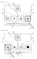
- FIG. 3 shows an image displayed on a screen of the second LCD 12 when the object display order changing program is executed.
- five icons icons 40h, 40i, 40j, 40k, and 401
- a balloon 42 a slide bar 44, and a cursor 46 are displayed on the screen.
- the icon 40 represents an image associated with a program (computer program executable by the CPU core 21). A user is allowed to boot a desired program by using the icon 40.
- 24 icons (icons 40a to 40x) in total are aligned in the order as shown in FIG. 4 , and some of the 24 icons are displayed on a predetermined area (hereinafter, referred to as an icon line display area) of the screen in accordance with the order.
- an area enclosed by dotted lines in FIG. 3 represents the icon line display area.
- a user selects an icon corresponding to a desired program from the icon line displayed on the icon line display area so as to cause the CPU core 21 to execute the desired program.
- the user is allowed to display and select any icon on the screen by scrolling the icon line displayed on the icon line display area.
- the balloon 42 represents an image for providing a user with information (information about the program corresponding to the icon, and the like) relating to the icon (icon 40j in an example shown in FIG. 3 ) displayed at the center of the icon line display area .
- the slide bar 44 provides a user with various functions in combination with the cursor 46.
- 24 squares displayed on the slide bar 44 correspond to 24 icons 40a to 40x, respectively.
- the cursor 46 indicates the icons, among the icons 40a to 40x, currently displayed on the icon line display area.
- a user is allowed to drag the cursor 46 along the slide bar 44 (that is, in the lateral direction) by using the stick 16, so as to move the cursor 46 to any point on the slide bar 44. Further, a user is also allowed to touch any point on the slide bar 44 so as to move the cursor 46 to the point.
- the icons displayed on the icon line display area are changed in accordance with a position of the cursor 46 being changed on the slide bar 44.
- a user is allowed to display a desired icon, among the icons 40a to 40x, on the icon line display area.
- an operation method for displaying a desired icon on the icon line display area used are various operation methods other than the method in which the slide bar 44 and the cursor 46 are used.
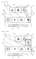
- FIG. 5 shows an exemplary screen displayed when a user touches the icon 40j by using the stick 16.
- the touched icon 40j is highlighted (for example, a contour thereof is highlighted).
- a scroll area 48 including the icon line is defined.
- the icon line can be scrolled.
- the stick 16 is touching a clearance between the icon 40h and the icon 40i shown in FIG .5 , the stick 16 is laterally slid, thereby enabling the icon line to be scrolled.
- an icon being dragged by a user is referred to as a "dragged icon” as necessary.
- the icon 40j is extracted from the icon line, the number of squares of the slide bar 44 is accordingly updated to 23, and display positions at which the icons 40h, 40i, 40k, and 401 are displayed are also updated (see FIG. 9 ).
- a desired icon may be extracted from the icon line.
- a saving area 50 is defined at a position distanced from the icon line display area.
- a user is allowed to insert a dragged icon in the icon line by dropping the dragged icon at any point outside the saving area 50 as well as at a position between two icons, adjacent to each other, included in the icon line.
- the dragged icon is typically inserted between two icons, adjacent to each other, which are included in the icon line and are closest to a point at which the dragged icon is dropped.
- the icon 40j may be inserted between the icon 40k and the icon 401. A case where the dragged icon is dropped in the saving area 50 will be described later.
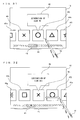
- a user drags the icon 40j to the right edge of the icon line display area as shown in FIG 13 , the icon line starts to be scrolled in the direction (that is, the left direction on the screen) indicated by an arrow in the figure.
- a right edge area 52R is defined near the right edge of the icon line display area
- a left edge area 52L is defined near the left edge of the icon line display area.
- a user is allowed to scroll the icon line leftward by positioning the dragged icon (the icon 40j in an example shown in FIG. 13 ) in the right edge area 52R.
- a user is allowed to scroll the icon line rightward by positioning the dragged icon in the left edge area 52L.
- the scroll-display of the icon line is continued while the dragged icon is positioned in the right edge area 52R or the left edge area 52L, and ends at a time when the dragged icon leaves the areas. Therefore, as shown in FIG. 13 , a user is allowed to insert the dragged icon in the icon line at a desired position by scrolling the icon line so as to display a desired destination (a clearance between any two icons, adjacent to each other, included in the icon line), and thereafter dragging to and dropping onto the desired destination the dragged icon.
- a user need not move the stick 16 away from the screen at all after a user touches a desired icon by using the stick 16 until the user inserts the icon in the icon line at a desired position, so that the display order in which the icons are displayed can be easily changed by performing once the sliding operation (that is, a series of operation from an operation of a user touching the screen by using the stick 16 so as to slide the screen to an operation of the user moving the stick 16 away from the screen).
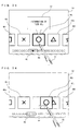
- an icon saved in the saving area 50 is referred to as a "saved icon" as necessary. While the saved icon exists, a mark 54 is displayed on the screen as shown in FIG. 16 .
- the mark 54 indicates a clearance between two icons, adjacent to each other, which are positioned near the center of the icon line displayed on the icon line display area, and when a user taps the stick 16 on the saved icon (that is, the stick 16 touching the saved icon is moved away from the screen without sliding the stick 16 on the screen), the saved icon is inserted in the clearance indicated by the mark 54.
- FIG. 17 shows an exemplary screen on which a user touches the icon 401 by using the stick 16 in the state (that is, a state where the saved icon exists) shown in FIG. 16 .
- the touched icon 401 is highlighted.
- some useful icon operation methods can be used.
- a state that is, a state where neither the dragged icon nor the saved icon exists
- the icon 40j on which the user taps the stick 16 opens that is, a program represented by the icon 40j is executed.
- the state that is, a state where neither the dragged icon nor the saved icon exists
- a user taps the stick 16 on an icon (the icon 40h, 40i, 40k, or 401) other than the icon 40j displayed at the center of the icon line display area, the icon line is scrolled such that the icon on which the user taps the stick 16 moves toward the center of the icon line display area.
- Some of the icon operation methods as described above may be performed by using a hardware switch (the operation switch section 14 shown in FIG. 2 ).
- a hardware switch the operation switch section 14 shown in FIG. 2 .
- the icon 40j displayed at the center of the icon line display area opens.
- an upper button that is, the upper portion of the cross switch 14a
- the icon 40j displayed at the center of the icon line display area is saved in the saving area 50 as shown in FIG. 16 .
- a user presses a left button (that is, the left portion of the cross switch 14a), the icon line is scrolled leftward on the screen by a distance corresponding to one icon. Furthermore, when in the state (that is, a state where the saved icon exists) shown in FIG. 16 a user presses a lower button (that is, the lower portion of the cross switch 14a), the saved icon 40j is inserted in the icon line at a clearance indicated by the mark 54.
- FIG. 21 shows a memory map of the RAM 24.
- the RAM 24 stores the object display order changing program, icon display order information, as shown in FIG. 4 , representing the display order in which the icons are displayed, icon image data corresponding to the respective icons, and various programs associated with the respective icons.
- the process is performed in three main process modes, a start mode, a dragging mode, and a saving mode, as shown in FIG. 22 .
- the start mode is a process mode for a state (for example, states shown in FIG. 3 , FIG. 5 , FIG. 6 , and FIG. 12 ) in which neither the dragged icon nor the saved icon exists.
- the dragging mode is a process mode for a state (for example, states shown in FIG. 8 , FIG. 9 , FIG. 10 , FIG. 13 , FIG. 15 , FIG. 19, and FIG. 20 ) in which the dragged icon exists.
- the saving mode is a process mode for a state (for example, the states shown in FIG. 16 , FIG. 17, and FIG. 18 ) where the dragged icon does not exist, and the saved icon exists). The process shifts among these three modes in accordance with an operation performed by a user.
- FIG. 23 shows contents of operations, performed by a user, corresponding to mode shift patterns, respectively.
- touch operation represents an operation performed by using the touch panel 15
- key operation represents an operation performed by using the operation switch section 14 (such as the cross switch 14a and the A button 14d shown in FIG. 1 ) shown in FIG. 2 .
- a shift from the start mode to the dragging mode is performed by a user dragging vertically one of the icons in the icon line displayed on the screen.
- a shift from the start mode to the saving mode is performed by a user pressing the upper button.
- a shift from the dragging mode to the start mode is performed by a user dropping the dragged icon outside the saving area 50.
- a shift from the dragging mode to the saving mode is performed by a user dropping the dragged icon in the saving area 50.
- a shift from the saving mode to the start mode is performed by a user tapping on the saved icon or pressing the lower button.
- a shift from the saving mode to the dragging mode is performed by a user dragging the saved icon.
- FIG. 24 is a flow chart showing a flow of process performed by the CPU core 21 in the start mode.
- step S10 the CPU core 21 determines whether or not a key input is made based on a signal from the operation switch section 14, and when the key input is made, the process advances to step S11, and otherwise the process advances to step S20.
- step S11 the CPU core 21 determines whether or not the upper button is pressed, and when the upper button is pressed, the process advances to step S12, and otherwise the process advances to step S13.
- step S12 the CPU core 21 withdraws the balloon 42, and saves, in the saving area 50, an icon displayed at the center of the icon line display area.
- step S12 ends, the process shifts to the saving mode.
- step S13 the CPU core 21 determines whether or not one of the right button or the left button is pressed, and when one of the right button or the left button is pressed, the process advances to step S14, and otherwise the process advances to step S16.
- step S14 the CPU core 21 scrolls and displays the icon line. Specifically, the CPU core 21 displays the icon line being scrolled rightward on the screen when the right button is pressed, and displays the icon line being scrolled leftward on the screen when the left button is pressed.
- step S15 the CPU core 21 determines whether or not the key input is being continued (that is, whether or not one of the right button or the left button is being still pressed), and when the key input is being continued, the process returns to step S14, and otherwise the process returns to step S10.
- step S16 the CPU core 21 determines whether or not the A button is pressed, and when the A button is pressed, the execution of the icon display order changing program is ended, and the icon displayed at the center of the icon line display area is opened (that is, the program associated with the icon displayed at the center thereof is started).
- step S20 the CPU core 21 detects a touch position based on a signal from the touch panel 15.
- the touch position is represented as a two-dimensional coordinate (X, Y) for which the X-axis direction represents the lateral direction of the screen, and the Y-axis direction represents the vertical direction of the screen.
- the touch position detected in step S20 is stored in the RAM 24 as a touch-on position (a touch position detected earliest after a state where the stick 16 does not touch the touch panel 15 shifts to a state where the stick 16 touches the touch panel 15).
- step S21 the CPU core 21 determines whether or not the touch position is on an icon, and when the touch position is on an icon, the process advances to step S26, and otherwise the process advances to step S22.
- step S22 the CPU core 21 determines whether or not the touch position is in the scroll area 48, and when the touch position is in the scroll area 48, the process advances to step S23, and otherwise the process returns to step S10.
- step S23 the CPU core 21 detects a touch position based on a signal from the touch panel 15.
- step S24 the CPU core 21 scrolls and displays the icon line based on the touch-on position (that is, the touch position detected and stored in step S20) and the most recent touch position (that is, the touch position detected in step S23). Specifically, the CPU core 21 determines a scrolling direction based on whether an X-coordinate value of the touch-on position is greater than or smaller than an X-coordinate value of the most recent touch position, and determines a scroll width (a moving distance over which the icon line moves on the screen) based on an absolute value of a difference between the X-coordinate value of the touch-on position and the X-coordinate value of the most recent touch position.
- step S25 the CPU core 21 determines whether or not touch-off is performed (that is, whether or not the stick 16 is moved away from the touch panel 15) based on a signal from the touch panel 15, and when the touch-off is performed, the process returns to step S10, and otherwise the process returns to step S23.
- step S26 the CPU core 21 highlights the icon touched by a user.
- step S27 the CPU core 21 detects a touch position based on a signal from the touch panel 15.
- step S28 the CPU core 21 determines whether or not amovingdistance (that is, an absolute value of a difference between the X-coordinate value of the touch-on position and an X-coordinate value of the most recent touch position) over which the touch position moves in the X-axis direction is greater than a predetermined threshold value, and when the moving distance over which the touch position moves in the X-axis direction is greater than the predetermined threshold value (in this case, a user intends to scroll the icon line laterally), the process advances to step S29, and otherwise the process advances to step S34.
- amovingdistance that is, an absolute value of a difference between the X-coordinate value of the touch-on position and an X-coordinate value of the most recent touch position
- step S29 the CPU core 21 detects a touch position based on a signal from the touch panel 15.
- step S30 the CPU core 21 determines whether or not amoving distance (that is, an absolute value of a difference between a Y-coordinate value of the touch-on position and a Y-coordinate value of the most recent touch position) over which the touch position moves in the Y-axis direction is greater than a predetermined threshold value, and when the moving distance over which the touch position moves in the Y-axis direction is greater than the predetermined threshold value (in this case, a user intends to extract a desired icon from the icon line), the process shifts to the dragging mode, and otherwise the process advances to step S31.
- a moving distance that is, an absolute value of a difference between a Y-coordinate value of the touch-on position and a Y-coordinate value of the most recent touch position
- the process shifts to the dragging mode, and otherwise the process advances to step S31.
- the threshold value used in step S30 may be increased in accordance with the moving distance in the X-axis direction being increased.
- a change rate for example, a change amount of the Y-axis coordinate value obtained during a most recent predetermined time period
- a predetermined threshold value may be determined, in step S30, instead of whether or not the moving distance over which the touch positionmoves in the Y-axis direction is greater than a predetermined threshold value.
- a change rate for example, a change amount of the Y-axis coordinate value obtained during a most recent predetermined time period
- step S31 the CPU core 21 scrolls and displays the icon line based on the touch-on position (that is, the touch position detected and stored in step S20) and the most recent touch position (that is, the touch position detected in step S29). Specifically, the CPU core 21 determines a scrolling direction based on whether the X-coordinate value of the touch-on position is greater than or smaller than an X-coordinate value of the most recent touch position, and determines a scroll width based on an absolute value of a difference between the X-coordinate value of the touch-on position and the X-coordinate value of the most recent touch position.
- step S32 the CPU core 21 determines whether or not the touch-off is performed, based on a signal from the touch panel 15, and when the touch-off is performed, the process advances to step S33, and otherwise the process returns to step S29.
- step S33 the CPU core 21 cancels the highlighting performed for the icon in step S26.
- step S34 the CPU core 21 determines whether or not the moving distance over which the touch position moves in the Y-axis direction is greater than a predetermined threshold value, and when the moving distance over which the touch position moves in the Y-axis direction is greater than the predetermined threshold value (in this case, a user intends to extract a desired icon from the icon line), the process shifts to the dragging mode, and otherwise the process advances to step S35.
- a predetermined threshold value in this case, a user intends to extract a desired icon from the icon line
- step S35 the CPU core 21 determines whether or not the touch-off is performed, based on a signal from the touch panel 15, and when the touch-off is performed (in this case, a user taps on a desired icon), the process advances to step S36, and otherwise the process returns to step S27.
- step S36 the CPU core 21 cancels the highlighting performed for the icon in step S26.
- step S37 the CPU core 21 determines whether or not the icon (that is, the icon having been most recently touched before the touch-off) on which a user taps is an icon displayed at the center of the icon line display area, and when the icon is the icon displayed at the center of the icon line display area, the execution of the icon display order changing program is ended, and the icon displayed at the center of the icon line on the screen is opened. Otherwise, the process advances to step S38.
- the icon that is, the icon having been most recently touched before the touch-off
- step S38 the CPU core 21 scrolls and displays the icon line so as to move, toward the center of the screen, the icon on which the user taps, and the process returns to step S10.
- FIG. 25 is a flow chart showing a flow of process performed by the CPU core 21 in the dragging mode.
- step S40 the CPU core 21 determines whether or not the touch-off is performed, based on a signal from the touch panel 15, and when the touch-off is performed, the process advances to step S45, and otherwise the process advances to step S41.
- step S41 the CPU core 21 detects a touch position based on a signal from the touch panel 15.
- step S42 the CPU core 21 moves the dragged icon so as to follow the most recent touch position (that is, the touch position detected in step S41), based on the most recent touch position.
- step S43 the CPU core 21 determines whether or not the touch position is in one of the right edge area 52R or the left edge area 52L, and when the touch position is in one of the right edge area 52R or the left edge area 52L, the process advances to step S44, and otherwise the process returns to step S40.
- step S44 the CPU core 21 scrolls and displays the icon line. Specifically, the CPU core 21 displays the icon line being scrolled leftward on the screen by a predetermined width when the touch position is in the right edge area 52R, and displays the icon line being scrolled rightward on the screen by a predetermined width when the touch position is in the left edge area 52L. The closer the touch position is to the edge of the icon line display area, the greater the scroll width may be (that is, the higher the scrolling rate may be).
- step S44 ends, the process returns to step S40.
- step S45 the CPU core 21 cancels the highlighting performed for the icon in step S26 or in step S66 described later.
- step S46 the CPU core 21 determines whether or not a touch-off position (a touch position having been most recently detected before touch-off is performed) is in the saving area 50, and when the touch-off position is in the saving area 50, the process advances to step S48, and otherwise the process advances to step S47.
- a touch-off position a touch position having been most recently detected before touch-off is performed
- step S47 the CPU core 21 inserts the dragged icon in the icon line. Specifically, the CPU core 21 inserts the dragged icon between two icons, adjacent to each other in the icon line, which are closest to the touch-off position.
- step S47 ends, the process shifts to the start mode.
- step S48 the CPU core 21 saves the dragged icon in the saving area 50. Specifically, the CPU core 21 moves the dragged icon to the center of the saving area 50.
- step S48 ends the process shifts to the saving mode.
- FIG. 26 is a flow chart showing a flow of process performed by the CPU core 21 in the saving mode.
- step S50 the CPU core 21 determines whether or not a key input is made, based on a signal from the operation switch section 14, and when a key input is made, the process advances to step S51, and otherwise the process advances to step S60.
- step S51 the CPU core 21 determines whether or not the lower button is pressed, and when the lower button is pressed, the process advances to step S52, and otherwise the process advances to step S53.
- step S52 the CPU core 21 inserts the saved icon in a clearance centered in the icon line displayed in the icon line display area.
- step S52 ends, the process shifts to the start mode.
- step S53 the CPU core 21 determines whether or not one of the right button or the left button is pressed, and when one of the right button or the left button is pressed, the process advances to step S54, and otherwise the process returns to step S50.
- step S54 the CPU core 21 scrolls and displays the icon line. Specifically, the CPU core 21 displays the icon line being scrolled rightward on the screen when the right button is pressed, and the CPU core 21 displays the icon line being scrolled leftward on the screen when the left button is pressed.
- step S55 the CPU core 21 determines whether or not the key input is being continued (that is, whether or not one of the right button or the left button is being still pressed), and when the key input is being continued, the process returns to step S54, and otherwise the process returns to step S50.
- step S60 the CPU core 21 detects a touch position, based on a signal from the touch panel 15.
- the touch position detected in step S60 is stored in the RAM 24 as the touch-on position.
- step S61 the CPU core 21 determines whether or not the touch position is on an icon, and when the touch position is on an icon, the process advances to step S66, and otherwise the process advances to step S62.
- step S62 the CPU core 21 determines whether or not the touch position is in the scroll area 48, and when the touch position is in the scroll area 48, the process advances to step S63, and otherwise the process returns to step S50.
- step S63 the CPU core 21 detects a touch position, based on a signal from the touch panel 15.
- step S64 the CPU core 21 scrolls and displays the icon line, based on the touch-on position (that is, the touch position detected and stored in step S60) and the most recent touch position (that is, the touch position detected in step S63). Specifically, the CPU core 21 determines a scrolling direction based on whether or not an X-coordinate value of the touch-on position is greater than or smaller than an X-coordinate value of the most recent touch position, and determines a scroll width based on an absolute value of a difference between the X-coordinate value of the touch-on position and the X-coordinate value of the most recent touch position.
- step S65 the CPU core 21 determines whether or not the touch-off is performed, based on a signal from the touch panel 15, and when the touch-off is performed, the process returns to step S50, and otherwise the process returns to step S63.
- step S66 the CPU core 21 highlights the icon touched by a user.
- step S67 the CPU core 21 determines whether or not the touch position is on the saved icon, and when the touch position is on the saved icon, the process advances to step S74, and otherwise (in this case, one of the icons in the icon line display area is touched) the process advances to step S68.
- step S68 the CPU core 21 detects a touch position, based on a signal from the touch panel 15.
- step S69 the CPU core 21 determines whether or not a moving distance over which the touch position moves in the Y-axis direction is greater than a predetermined threshold value, and when the moving distance over which the touch position moves in the Y-axis direction is greater than the predetermined threshold value (in this case, a user intends to extract a desired icon from the icon line so as to interchange between the desired icon and the saved icon), the process advances to step S73, and otherwise the process advances to step S70.
- a predetermined threshold value in this case, a user intends to extract a desired icon from the icon line so as to interchange between the desired icon and the saved icon
- step S70 the CPU core 21 scrolls and displays the icon line, based on the touch-on position(that is, the touch position detected and stored in step S60) and the most recent touch position (that is, the touch position detected in step S68). Specifically, the CPU core 21 determines a scrolling direction based on whether the X-coordinate value of the touch-on position is greater than or smaller than an X-coordinate value of the most recent touch position, and determines a scroll width based on an absolute value of a difference between the X-coordinate value of the touch-on position and the X-coordinate value of the most recent touch position.
- step S71 the CPU core 21 determines whether or not the touch-off is performed, based on a signal from the touch panel 15, and when the touch-off is performed, the process advances to step S72, and otherwise the process returns to step S68.
- step S72 the CPU core 21 removes the highlight of the icon, which is provided in step S66.
- step S73 the CPU core 21 interchanges between the saved icon and the icon being currently touched. Specifically, the CPU core 21 moves the saved icon to a position of the icon being currently touched so as to interchange between the saved icon and the icon being currently touched.
- the process step of step S73 ends, the process shifts to the dragging mode.
- step S74 the CPU core 21 detects a touch position, based on a signal from the touch panel 15.
- step S75 the CPU core 21 moves the saved icon so as to follow the most recent touchposition (that is, the touchposition detected in step S74), based on the most recent touch position.
- step S76 the CPU core 21 determines whether or not the moving distance (a moving distance based on both a moving distance in the X-axis direction and a moving distance in the Y-axis direction, such as, for example, a distance between the touch-on position and the most recent touch position) over which the touch position moves is greater than a predetermined threshold value, and when the moving distance over which the touch position move is greater than the predetermined threshold value (in this case, a user intends to drag the saved icon), the process shifts to the dragging mode, and otherwise the process advances to step S77.
- the moving distance a moving distance based on both a moving distance in the X-axis direction and a moving distance in the Y-axis direction, such as, for example, a distance between the touch-on position and the most recent touch position
- step S77 the CPU core 21 determines whether or not the touch-off is performed, based on a signal from the touch panel 15, and when the touch-off is performed (in this case, a user intends to tap on the saved icon), the process advances to step S78, and otherwise the process returns to step S74.
- step S78 the CPU core 21 removes the highlight of the icon, which is provided in step S66.
- step S79 the CPU core 21 inserts the saved icon in the icon line displayed on the icon line display area at the centered clearance.
- step S79 ends the process shifts to the start mode.
- a user is allowed to easily change the display order in which a plurality of objects are displayed on the icon line display area.
- the present embodiment in a case where an icon included in the icon line displayed on the icon line display area is touched by the stick 16, when the stick 16 touching the icon is laterally slid, it is possible to scroll the entire icon line, and when the stick 16 touching the icon is vertically slid, it is possible to extract and drag the touched icon from the icon line. Therefore, unlike in a conventional art, it is unnecessary to provide a scroll box in an area other than a display area (corresponding to the icon line display area of the present embodiment) of the icon line, thereby making effective use of a limited screen size.
- the wider an area allocated as a display area of the icon line is, the narrower an area for providing a scroll box is, so that the scroll box is narrowed, and it is difficult to designate a position on the scroll box by using a pointing device.
- a wide area can be used for the scroll area 48 so as to include the display area of the icon line, and therefore the display area of the icon line can be sufficiently widen without deteriorating the operability for scrolling operation.
- a touch panel is used
- the present invention is not limited thereto, and any other coordinate input means such as a mouse, a joystick, or a touch pad may be used.
- the present invention when the dragged icon is dropped at any desired point outside the saving area 50, the dragged icon is inserted in the icon line, the present invention is not limited thereto, and when the dragged icon is dropped in a specific area (for example, an area distanced from the icon line by a predetermined distance or less), the dragged icon may be inserted in the icon line.
- the icon line display area as shown in FIG.3 , the scroll area 48 as shown in FIG. 7 , the saving area 50 as shown in FIG. 11 , and the right edge area 52R and the left edge area 52L as shown in FIG. 14 are each simply an example, the position and the size thereof may be changed as necessary.
- each of the right edge area 52R and the left edge area 52L may extend from the top of the screen to the bottom thereof.
- step S43 and step S44 shown in FIG. 25 when the touch position is in the right edge area 52R or the left edge area 52L, the icon line is scrolled and displayed.
- the present invention is not limited thereto.
- the icon line may be scrolled and displayed.
- step S46 shown in FIG. 25 the similar determination may be made.
- step S28, step S30, and step S34 shown in FIG. 24 , and step S69 shown in FIG. 26 may be individually set as an appropriate value.
- the icon line is displayed so as to be aligned laterally in line
- the present invention is not limited thereto, and the icon line may be displayed so as to be aligned vertically in line.
- the number of the icon lines displayed on the icon line display area is one, the present invention is not limited thereto, and the number of the icon lines displayed on the icon line display area may be greater than one.
- the display order in which a plurality of icons are displayed is changed, the present invention is not limited thereto.
- the display order in which any other objects, other than icons, such as images, characters, marks, and 3D obj ects, are displayed can be effectively changed.
- the saving area 50 may simultaneously save a plurality of icons.
- FIG. 27 shows an exemplary screen displayed when the icon 40a, the icon 40f, and the icon 40j are sequentially saved in the saving area 50 in order, respectively.
- the maximum number of the icons which are allowed to be saved in the saving area 50 may be previously set. In this case, when the saving area 50 saves the maximum number of icons (saved icons), a new icon can be saved in the saving area only by returning one of the maximum number of saved icons to the icon line.
- interchange between the icons can be performed as described with reference to FIG. 20 .
- a user touches the icon 401 by using the stick 16 so as to slide the stick 16 touching the icon 401 upward on the screen, the icon 401 moves upward so as to follow the stick 16 as shown in FIG. 28 , and the icon 401 is extracted from the icon line, and further interchange between the icon 401 and the icon 40a which has been earliest saved in the saving area 50 may be performed such that the icon 40a is inserted in the icon line.
- FIG. 27 a user touches the icon 401 by using the stick 16 so as to slide the stick 16 touching the icon 401 upward on the screen
- the icon 401 moves upward so as to follow the stick 16 as shown in FIG. 28
- the icon 401 is extracted from the icon line
- further interchange between the icon 401 and the icon 40a which has been earliest saved in the saving area 50 may be performed such that the icon 40a is inserted in the icon line.
- a user touches the icon 401 by using the stick 16, and slides the stick 16 touching the icon 401 upward on the screen, and thereafter, as shown in FIG. 29 , the icon 401 is dragged to and dropped onto a desired saved icon (the icon 40f in an example shown in FIG. 29 ) among a plurality of the saved icons saved in the saving area 50.
- a desired saved icon the icon 40f in an example shown in FIG. 29
- interchange between the icon 40f and the icon 40l may be performed such that the icon 401 is saved in the saving area 50, and the icon 40f is inserted in the icon line.
Landscapes
- Engineering & Computer Science (AREA)
- Theoretical Computer Science (AREA)
- General Engineering & Computer Science (AREA)
- Human Computer Interaction (AREA)
- Physics & Mathematics (AREA)
- General Physics & Mathematics (AREA)
- Software Systems (AREA)
- User Interface Of Digital Computer (AREA)
- Digital Computer Display Output (AREA)
Applications Claiming Priority (1)
| Application Number | Priority Date | Filing Date | Title |
|---|---|---|---|
| JP2008114434A JP4171770B1 (ja) | 2008-04-24 | 2008-04-24 | オブジェクト表示順変更プログラム及び装置 |
Publications (3)
| Publication Number | Publication Date |
|---|---|
| EP2112594A2 true EP2112594A2 (de) | 2009-10-28 |
| EP2112594A3 EP2112594A3 (de) | 2011-08-31 |
| EP2112594B1 EP2112594B1 (de) | 2017-12-20 |
Family
ID=39985891
Family Applications (1)
| Application Number | Title | Priority Date | Filing Date |
|---|---|---|---|
| EP08011707.0A Active EP2112594B1 (de) | 2008-04-24 | 2008-06-27 | Programm und Vorrichtung zur Änderung der Objektanzeigereihenfolge |
Country Status (3)
| Country | Link |
|---|---|
| US (1) | US9116721B2 (de) |
| EP (1) | EP2112594B1 (de) |
| JP (1) | JP4171770B1 (de) |
Cited By (11)
| Publication number | Priority date | Publication date | Assignee | Title |
|---|---|---|---|---|
| GB2471169A (en) * | 2009-06-11 | 2010-12-22 | Apple Inc | Presenting and rearranging icons representing media items in a playlist in a graphical user interface |
| EP2450780A1 (de) * | 2010-09-24 | 2012-05-09 | Nintendo Co., Ltd. | Informationsverarbeitungsprogramm, Informationsverarbeitungsvorrichtung, Informationsverarbeitungssystem und Informationsverarbeitungsverfahren |
| EP2405334A3 (de) * | 2010-07-06 | 2012-08-29 | Aisin Aw Co., Ltd. | Anzeigevorrichtung, Anzeigeverfahren und Programm |
| CN102750082A (zh) * | 2011-04-22 | 2012-10-24 | 索尼公司 | 信息处理设备、信息处理方法和程序 |
| US8429530B2 (en) | 2009-06-11 | 2013-04-23 | Apple Inc. | User interface for media playback |
| US20130198670A1 (en) * | 2012-01-20 | 2013-08-01 | Charles PELLETIER | Environment controller providing state-based control menus and environment control method |
| WO2013148605A1 (en) * | 2012-03-25 | 2013-10-03 | Masimo Corporation | Physiological monitor touchscreen interface |
| WO2014002050A3 (en) * | 2012-06-29 | 2014-04-17 | Nokia Corporation | Method and apparatus for task chaining |
| WO2014075041A1 (en) * | 2012-11-12 | 2014-05-15 | Microsoft Corporation | Cross slide gesture |
| EP2600231A4 (de) * | 2010-07-30 | 2016-04-27 | Sony Computer Entertainment Inc | Elektronische vorrichtung, verfahren zur anzeige von objekten und suchverfahren |
| US9575652B2 (en) | 2012-03-31 | 2017-02-21 | Microsoft Technology Licensing, Llc | Instantiable gesture objects |
Families Citing this family (121)
| Publication number | Priority date | Publication date | Assignee | Title |
|---|---|---|---|---|
| US8225231B2 (en) | 2005-08-30 | 2012-07-17 | Microsoft Corporation | Aggregation of PC settings |
| US7509588B2 (en) | 2005-12-30 | 2009-03-24 | Apple Inc. | Portable electronic device with interface reconfiguration mode |
| US8296684B2 (en) | 2008-05-23 | 2012-10-23 | Hewlett-Packard Development Company, L.P. | Navigating among activities in a computing device |
| US8683362B2 (en) | 2008-05-23 | 2014-03-25 | Qualcomm Incorporated | Card metaphor for activities in a computing device |
| US10313505B2 (en) | 2006-09-06 | 2019-06-04 | Apple Inc. | Portable multifunction device, method, and graphical user interface for configuring and displaying widgets |
| US8519964B2 (en) | 2007-01-07 | 2013-08-27 | Apple Inc. | Portable multifunction device, method, and graphical user interface supporting user navigations of graphical objects on a touch screen display |
| KR101346732B1 (ko) * | 2007-01-29 | 2013-12-31 | 삼성전자주식회사 | 멀티선택 장치 및 방법 |
| US8619038B2 (en) | 2007-09-04 | 2013-12-31 | Apple Inc. | Editing interface |
| US20110080391A1 (en) * | 2008-06-03 | 2011-04-07 | Christopher Brown | Display device |
| JP5500855B2 (ja) * | 2008-07-11 | 2014-05-21 | キヤノン株式会社 | 情報処理装置及びその制御方法 |
| US8427464B2 (en) * | 2008-07-16 | 2013-04-23 | Sharp Kabushiki Kaisha | Display device |
| CN102099775B (zh) | 2008-07-17 | 2014-09-24 | 日本电气株式会社 | 信息处理装置、记录有程序的存储介质以及目标移动方法 |
| US10572136B2 (en) * | 2008-12-29 | 2020-02-25 | Ngc Networks Us, Llc | Interactive display systems, methods, and computer program products |
| JP4880003B2 (ja) * | 2009-01-20 | 2012-02-22 | シャープ株式会社 | 情報処理装置、制御方法及びプログラム |
| US8762886B2 (en) * | 2009-07-30 | 2014-06-24 | Lenovo (Singapore) Pte. Ltd. | Emulating fundamental forces of physics on a virtual, touchable object |
| US20110029864A1 (en) * | 2009-07-30 | 2011-02-03 | Aaron Michael Stewart | Touch-Optimized Approach for Controlling Computer Function Using Touch Sensitive Tiles |
| US20110029904A1 (en) * | 2009-07-30 | 2011-02-03 | Adam Miles Smith | Behavior and Appearance of Touch-Optimized User Interface Elements for Controlling Computer Function |
| US8656314B2 (en) * | 2009-07-30 | 2014-02-18 | Lenovo (Singapore) Pte. Ltd. | Finger touch gesture for joining and unjoining discrete touch objects |
| US9158409B2 (en) * | 2009-09-29 | 2015-10-13 | Beijing Lenovo Software Ltd | Object determining method, object display method, object switching method and electronic device |
| KR101648747B1 (ko) * | 2009-10-07 | 2016-08-17 | 삼성전자 주식회사 | 복수의 터치 센서를 이용한 ui 제공방법 및 이를 이용한 휴대 단말기 |
| JPWO2011055816A1 (ja) * | 2009-11-09 | 2013-03-28 | 株式会社キャメロット | 情報端末及び入力制御プログラム |
| JP5608360B2 (ja) * | 2009-12-04 | 2014-10-15 | オリンパス株式会社 | 顕微鏡コントローラ及び顕微鏡コントローラを備える顕微鏡システム |
| TWI414976B (zh) * | 2009-12-15 | 2013-11-11 | Pegatron Corp | 使用者介面的控制方法 |
| JP5581757B2 (ja) * | 2010-03-18 | 2014-09-03 | コニカミノルタ株式会社 | 画像処理装置、インターフェイス画面表示方法およびコンピュータプログラム |
| US8881060B2 (en) | 2010-04-07 | 2014-11-04 | Apple Inc. | Device, method, and graphical user interface for managing folders |
| US10788976B2 (en) | 2010-04-07 | 2020-09-29 | Apple Inc. | Device, method, and graphical user interface for managing folders with multiple pages |
| JP5533165B2 (ja) | 2010-04-09 | 2014-06-25 | ソニー株式会社 | 情報処理装置、情報処理方法およびプログラム |
| US20120326981A1 (en) * | 2010-05-12 | 2012-12-27 | Nec Corporation | Information processing terminal, terminal operation method and computer-readable medium |
| JP5556398B2 (ja) * | 2010-06-08 | 2014-07-23 | ソニー株式会社 | 情報処理装置、情報処理方法およびプログラム |
| KR101782639B1 (ko) * | 2010-06-16 | 2017-09-27 | 삼성전자주식회사 | 휴대단말기의 사용 방법 |
| JP5659576B2 (ja) * | 2010-06-22 | 2015-01-28 | コニカミノルタ株式会社 | 画像処理装置、スクロール表示方法およびコンピュータプログラム |
| JP5067448B2 (ja) * | 2010-06-24 | 2012-11-07 | コニカミノルタビジネステクノロジーズ株式会社 | 画像処理装置、インタフェース画面表示方法及びコンピュータプログラム |
| JP5454405B2 (ja) * | 2010-07-21 | 2014-03-26 | ヤマハ株式会社 | 音響調整卓 |
| JP5561031B2 (ja) * | 2010-08-30 | 2014-07-30 | コニカミノルタ株式会社 | 表示処理装置、スクロール表示方法、およびコンピュータプログラム |
| JP5810498B2 (ja) * | 2010-09-22 | 2015-11-11 | コニカミノルタ株式会社 | 表示処理装置およびコンピュータプログラム |
| JP5832077B2 (ja) * | 2010-09-24 | 2015-12-16 | 任天堂株式会社 | 情報処理プログラム、情報処理装置、情報処理システム、及び情報処理方法 |
| JP5434887B2 (ja) * | 2010-11-02 | 2014-03-05 | コニカミノルタ株式会社 | 表示処理装置およびコンピュータプログラム |
| JP5304776B2 (ja) * | 2010-12-16 | 2013-10-02 | コニカミノルタ株式会社 | 画像形成システムおよびプログラム |
| US20120159395A1 (en) | 2010-12-20 | 2012-06-21 | Microsoft Corporation | Application-launching interface for multiple modes |
| US8689123B2 (en) | 2010-12-23 | 2014-04-01 | Microsoft Corporation | Application reporting in an application-selectable user interface |
| US9104307B2 (en) | 2011-05-27 | 2015-08-11 | Microsoft Technology Licensing, Llc | Multi-application environment |
| US9658766B2 (en) | 2011-05-27 | 2017-05-23 | Microsoft Technology Licensing, Llc | Edge gesture |
| US9158445B2 (en) | 2011-05-27 | 2015-10-13 | Microsoft Technology Licensing, Llc | Managing an immersive interface in a multi-application immersive environment |
| KR101380968B1 (ko) * | 2011-06-02 | 2014-04-04 | 주식회사 팬택 | 그래픽 사용자 인터페이스 제공 장치 및 방법 |
| JP2013033330A (ja) * | 2011-08-01 | 2013-02-14 | Sony Corp | 情報処理装置、情報処理方法およびプログラム |
| US8687023B2 (en) * | 2011-08-02 | 2014-04-01 | Microsoft Corporation | Cross-slide gesture to select and rearrange |
| US20130057587A1 (en) * | 2011-09-01 | 2013-03-07 | Microsoft Corporation | Arranging tiles |
| US10353566B2 (en) | 2011-09-09 | 2019-07-16 | Microsoft Technology Licensing, Llc | Semantic zoom animations |
| US8922575B2 (en) | 2011-09-09 | 2014-12-30 | Microsoft Corporation | Tile cache |
| US9557909B2 (en) | 2011-09-09 | 2017-01-31 | Microsoft Technology Licensing, Llc | Semantic zoom linguistic helpers |
| US9146670B2 (en) | 2011-09-10 | 2015-09-29 | Microsoft Technology Licensing, Llc | Progressively indicating new content in an application-selectable user interface |
| US20130067392A1 (en) * | 2011-09-12 | 2013-03-14 | Microsoft Corporation | Multi-Input Rearrange |
| KR101916742B1 (ko) * | 2011-11-10 | 2018-11-09 | 삼성전자 주식회사 | 휴대 단말기의 사용자 인터페이스 제공 방법 및 장치 |
| JP5852857B2 (ja) * | 2011-11-21 | 2016-02-03 | シャープ株式会社 | 表示システムおよび表示プログラム |
| US10776103B2 (en) | 2011-12-19 | 2020-09-15 | Majen Tech, LLC | System, method, and computer program product for coordination among multiple devices |
| JP5834895B2 (ja) * | 2011-12-26 | 2015-12-24 | ブラザー工業株式会社 | 画像処理装置及びプログラム |
| WO2013116919A1 (en) * | 2012-02-07 | 2013-08-15 | Research In Motion Limited | Methods and devices for merging contact records |
| JP5797580B2 (ja) * | 2012-02-16 | 2015-10-21 | シャープ株式会社 | 入力制御装置、電子機器、入力制御方法、プログラムおよび記録媒体 |
| JP2013196414A (ja) * | 2012-03-21 | 2013-09-30 | Nintendo Co Ltd | 情報処理プログラム、情報処理装置、情報処理システムおよび表示制御方法 |
| JP5649229B2 (ja) * | 2012-04-26 | 2015-01-07 | 京セラドキュメントソリューションズ株式会社 | 表示入力装置および画像形成装置 |
| KR101984154B1 (ko) * | 2012-07-16 | 2019-05-30 | 삼성전자 주식회사 | 터치 및 제스처 입력을 이용한 단말의 제어 방법 및 그 단말 |
| KR102061776B1 (ko) * | 2012-09-05 | 2020-01-02 | 후아웨이 테크놀러지 컴퍼니 리미티드 | 객체 위치를 변경하기 위한 방법 및 그 전자 장치 |
| JP6027373B2 (ja) * | 2012-09-11 | 2016-11-16 | 任天堂株式会社 | 情報処理プログラム、表示制御装置、表示制御システム及び表示方法 |
| USD743993S1 (en) * | 2012-11-30 | 2015-11-24 | Samsung Electronics Co., Ltd. | Display screen or portion thereof with graphical user interface |
| JP2014182652A (ja) * | 2013-03-19 | 2014-09-29 | Canon Inc | 情報処理装置およびその制御方法、ならびにプログラム |
| USD745549S1 (en) * | 2013-06-05 | 2015-12-15 | Samsung Electronics Co., Ltd. | Display screen or portion thereof with graphical user interface |
| USD738394S1 (en) | 2013-06-09 | 2015-09-08 | Apple Inc. | Display screen or portion thereof with animated graphical user interface |
| USD749622S1 (en) * | 2013-06-10 | 2016-02-16 | Apple Inc. | Display screen or portion thereof with animated graphical user interface |
| USD741350S1 (en) | 2013-06-10 | 2015-10-20 | Apple Inc. | Display screen or portion thereof with animated graphical user interface |
| JP6178741B2 (ja) * | 2013-09-24 | 2017-08-09 | 京セラドキュメントソリューションズ株式会社 | 電子機器 |
| US9805114B2 (en) * | 2013-09-30 | 2017-10-31 | Microsoft Technology Licensing, Llc | Composable selection model through reusable component |
| JP6393325B2 (ja) | 2013-10-30 | 2018-09-19 | アップル インコーポレイテッドApple Inc. | 関連するユーザインターフェースオブジェクトの表示 |
| USD772278S1 (en) | 2013-12-18 | 2016-11-22 | Apple Inc. | Display screen or portion thereof with animated graphical user interface |
| US11914419B2 (en) | 2014-01-23 | 2024-02-27 | Apple Inc. | Systems and methods for prompting a log-in to an electronic device based on biometric information received from a user |
| CN106233241B (zh) | 2014-01-23 | 2020-03-31 | 苹果公司 | 虚拟计算机键盘 |
| USD769892S1 (en) | 2014-05-30 | 2016-10-25 | Apple Inc. | Display screen or portion thereof with graphical user interface |
| TWI530864B (zh) * | 2014-08-19 | 2016-04-21 | 宏碁股份有限公司 | 可攜式電子裝置以及使用者介面操作方法 |
| JP6459358B2 (ja) * | 2014-09-30 | 2019-01-30 | キヤノンマーケティングジャパン株式会社 | 情報処理装置、制御方法、及びプログラム |
| USD788159S1 (en) | 2014-10-14 | 2017-05-30 | Tencent Technology (Shenzhen) Company Limited | Display screen or portion thereof with graphical user interface |
| USD791801S1 (en) * | 2014-10-14 | 2017-07-11 | Tencent Technology (Shenzhen) Company Limited | Display screen or portion thereof with graphical user interface |
| USD797769S1 (en) * | 2014-10-14 | 2017-09-19 | Tencent Technology (Shenzhen) Company Limited | Display screen or portion thereof with graphical user interface |
| KR102318610B1 (ko) * | 2015-01-30 | 2021-10-28 | 삼성전자주식회사 | 모바일 디바이스 및 모바일 디바이스의 디스플레이 방법 |
| CN107408117B (zh) * | 2015-03-13 | 2021-01-12 | 瑞典爱立信有限公司 | 用于手持操作的设备及其方法 |
| JP2016218841A (ja) * | 2015-05-22 | 2016-12-22 | 京セラドキュメントソリューションズ株式会社 | 表示装置、及び画像形成装置 |
| USD765699S1 (en) | 2015-06-06 | 2016-09-06 | Apple Inc. | Display screen or portion thereof with graphical user interface |
| JP6643776B2 (ja) * | 2015-06-11 | 2020-02-12 | 株式会社バンダイナムコエンターテインメント | 端末装置及びプログラム |
| US10345991B2 (en) * | 2015-06-16 | 2019-07-09 | International Business Machines Corporation | Adjusting appearance of icons in an electronic device |
| USD798331S1 (en) | 2015-08-03 | 2017-09-26 | Google Inc. | Display screen with animated graphical user interface |
| USD888733S1 (en) * | 2015-08-03 | 2020-06-30 | Google Llc | Display screen with animated graphical user interface |
| USD849027S1 (en) | 2015-08-03 | 2019-05-21 | Google Llc | Display screen with animated graphical user interface |
| USD781328S1 (en) * | 2015-08-03 | 2017-03-14 | Google Inc. | Display screen with animated graphical user interface |
| USD848458S1 (en) | 2015-08-03 | 2019-05-14 | Google Llc | Display screen with animated graphical user interface |
| USD798321S1 (en) * | 2015-08-13 | 2017-09-26 | Google Inc. | Display panel portion with transitional graphical user interface |
| JP6532372B2 (ja) * | 2015-10-06 | 2019-06-19 | キヤノン株式会社 | 表示制御装置、その制御方法およびプログラム |
| JP6555189B2 (ja) * | 2016-05-17 | 2019-08-07 | 京セラドキュメントソリューションズ株式会社 | 表示制御装置、及び表示制御方法 |
| JP6555188B2 (ja) * | 2016-05-17 | 2019-08-07 | 京セラドキュメントソリューションズ株式会社 | 表示制御装置、及び表示制御方法 |
| US12175065B2 (en) | 2016-06-10 | 2024-12-24 | Apple Inc. | Context-specific user interfaces for relocating one or more complications in a watch or clock interface |
| DK201670595A1 (en) | 2016-06-11 | 2018-01-22 | Apple Inc | Configuring context-specific user interfaces |
| US11816325B2 (en) | 2016-06-12 | 2023-11-14 | Apple Inc. | Application shortcuts for carplay |
| JP6767799B2 (ja) * | 2016-07-12 | 2020-10-14 | 任天堂株式会社 | 情報処理プログラム、情報処理装置、情報処理装置の制御方法および情報処理システム |
| AU2017100879B4 (en) * | 2016-07-29 | 2017-09-28 | Apple Inc. | Systems, devices, and methods for dynamically providing user interface controls at touch-sensitive secondary display |
| USD846587S1 (en) | 2017-06-04 | 2019-04-23 | Apple Inc. | Display screen or portion thereof with animated graphical user interface |
| US10809882B1 (en) * | 2017-06-30 | 2020-10-20 | Pinterest, Inc. | Insertion of object identifiers into a feed of object identifiers |
| USD861704S1 (en) | 2017-09-11 | 2019-10-01 | Apple Inc. | Electronic device with graphical user interface |
| JP6724259B2 (ja) * | 2017-10-31 | 2020-07-15 | 富士フイルム株式会社 | 操作装置、その作動方法および作動プログラム |
| US11079919B1 (en) | 2018-05-10 | 2021-08-03 | Wells Fargo Bank, N.A. | Personal computing devices with improved graphical user interfaces |
| USD916862S1 (en) | 2018-05-10 | 2021-04-20 | Wells Fargo Bank, N.A. | Display screen or portion thereof with graphical user interface |
| USD879817S1 (en) * | 2018-05-21 | 2020-03-31 | Canva Pty Ltd. | Display screen or portion thereof with a graphical user interface |
| USD879818S1 (en) * | 2018-05-21 | 2020-03-31 | Canva Pty Ltd. | Display screen or portion thereof with an animated graphical user interface |
| USD879132S1 (en) | 2018-06-03 | 2020-03-24 | Apple Inc. | Electronic device with graphical user interface |
| USD877175S1 (en) | 2018-06-04 | 2020-03-03 | Apple Inc. | Electronic device with graphical user interface |
| CN110858154B (zh) * | 2018-08-24 | 2023-09-01 | 北京金山云网络技术有限公司 | 一种轮播图的切换显示方法、装置、电子设备及存储介质 |
| USD883319S1 (en) | 2018-10-29 | 2020-05-05 | Apple Inc. | Electronic device with graphical user interface |
| US11675476B2 (en) | 2019-05-05 | 2023-06-13 | Apple Inc. | User interfaces for widgets |
| USD956060S1 (en) * | 2019-08-16 | 2022-06-28 | Aristocrat Technologies Australia Pty Limited | Display screen or portion thereof with graphical user interface |
| AU2019216700A1 (en) | 2019-08-16 | 2021-03-04 | Aristocrat Technologies Australia Pty Limited | Gaming device with upgradeable symbol awards |
| JP7508931B2 (ja) * | 2020-07-31 | 2024-07-02 | セイコーエプソン株式会社 | 画像表示方法、画像表示装置及び表示制御プログラム |
| USD994693S1 (en) * | 2020-12-15 | 2023-08-08 | Samsung Electronics Co., Ltd. | Display screen or portion thereof with transitional graphical user interface |
| USD993969S1 (en) * | 2020-12-15 | 2023-08-01 | Samsung Electronics Co., Ltd. | Display screen or portion thereof with graphical user interface |
| USD984461S1 (en) | 2021-06-04 | 2023-04-25 | Apple Inc. | Display screen or portion thereof with graphical user interface |
| TWD226263S (zh) * | 2022-10-24 | 2023-07-01 | 達擎股份有限公司 | 電腦程式產品之圖像 |
Citations (3)
| Publication number | Priority date | Publication date | Assignee | Title |
|---|---|---|---|---|
| US5966122A (en) | 1996-03-08 | 1999-10-12 | Nikon Corporation | Electronic camera |
| WO2007067858A2 (en) | 2005-12-08 | 2007-06-14 | Apple Inc. | List scrolling in response to moving contact over list of index symbols |
| US20070186178A1 (en) | 2006-02-06 | 2007-08-09 | Yahoo! Inc. | Method and system for presenting photos on a website |
Family Cites Families (23)
| Publication number | Priority date | Publication date | Assignee | Title |
|---|---|---|---|---|
| JP2677737B2 (ja) | 1992-06-24 | 1997-11-17 | 株式会社東芝 | 半導体装置 |
| JPH0612217A (ja) | 1992-06-26 | 1994-01-21 | Toshiba Corp | パーソナルコンピュータ及びメニュ画面表示方法 |
| US5497455A (en) * | 1992-06-26 | 1996-03-05 | Kabushiki Kaisha Toshiba | Portable computer which has a task selection menu allowing easy selection and execution of arbitrary application software without entering a command |
| JPH0720983A (ja) * | 1993-06-30 | 1995-01-24 | Casio Comput Co Ltd | コマンド出力装置 |
| US5548702A (en) * | 1993-12-23 | 1996-08-20 | International Business Machines Corporation | Scrolling a target window during a drag and drop operation |
| JPH1097407A (ja) | 1996-09-19 | 1998-04-14 | Toshiba Corp | 携帯型情報機器およびアイコンの表示制御方法 |
| JP3370586B2 (ja) | 1997-12-10 | 2003-01-27 | 京セラ株式会社 | デジタルカメラ |
| JP2000267783A (ja) * | 1999-03-18 | 2000-09-29 | Sharp Corp | 表示内容の移動制御装置及び表示内容の移動制御方法 |
| US6590568B1 (en) * | 2000-11-20 | 2003-07-08 | Nokia Corporation | Touch screen drag and drop input technique |
| US7017118B1 (en) * | 2000-12-29 | 2006-03-21 | International Business Machines Corp. | Method and apparatus for reordering data items |
| US6690387B2 (en) * | 2001-12-28 | 2004-02-10 | Koninklijke Philips Electronics N.V. | Touch-screen image scrolling system and method |
| JP2004283325A (ja) * | 2003-03-20 | 2004-10-14 | Konica Minolta Holdings Inc | 医用画像処理装置、医用ネットワークシステム及び医用画像処理装置のためのプログラム |
| JP2005169880A (ja) | 2003-12-12 | 2005-06-30 | Canon Inc | 印刷装置、撮像装置及びダイレクトプリントシステム |
| JP2005227826A (ja) * | 2004-02-10 | 2005-08-25 | Seiko Epson Corp | 画像順序づけ装置、画像順序づけ方法およびコンピュータプログラム |
| US7437005B2 (en) * | 2004-02-17 | 2008-10-14 | Microsoft Corporation | Rapid visual sorting of digital files and data |
| JP2005321915A (ja) * | 2004-05-07 | 2005-11-17 | Sony Corp | 情報処理装置および情報処理方法、並びに、プログラム |
| US8281241B2 (en) * | 2004-06-28 | 2012-10-02 | Nokia Corporation | Electronic device and method for providing extended user interface |
| JP4701027B2 (ja) * | 2004-09-02 | 2011-06-15 | キヤノン株式会社 | 情報処理装置、制御方法及びプログラム |
| US8296684B2 (en) * | 2008-05-23 | 2012-10-23 | Hewlett-Packard Development Company, L.P. | Navigating among activities in a computing device |
| JP4795193B2 (ja) | 2006-10-13 | 2011-10-19 | キヤノン株式会社 | 画像表示装置及びその制御方法及びプログラム |
| US20090119614A1 (en) * | 2007-11-07 | 2009-05-07 | Nokia Corporation | Method, Apparatus and Computer Program Product for Heirarchical Navigation with Respect to Content Items of a Media Collection |
| US20090187842A1 (en) * | 2008-01-22 | 2009-07-23 | 3Dlabs Inc., Ltd. | Drag and Drop User Interface for Portable Electronic Devices with Touch Sensitive Screens |
| KR101477743B1 (ko) * | 2008-06-16 | 2014-12-31 | 삼성전자 주식회사 | 단말 및 그의 기능 수행 방법 |
-
2008
- 2008-04-24 JP JP2008114434A patent/JP4171770B1/ja active Active
- 2008-04-29 US US12/149,266 patent/US9116721B2/en active Active
- 2008-06-27 EP EP08011707.0A patent/EP2112594B1/de active Active
Patent Citations (3)
| Publication number | Priority date | Publication date | Assignee | Title |
|---|---|---|---|---|
| US5966122A (en) | 1996-03-08 | 1999-10-12 | Nikon Corporation | Electronic camera |
| WO2007067858A2 (en) | 2005-12-08 | 2007-06-14 | Apple Inc. | List scrolling in response to moving contact over list of index symbols |
| US20070186178A1 (en) | 2006-02-06 | 2007-08-09 | Yahoo! Inc. | Method and system for presenting photos on a website |
Cited By (25)
| Publication number | Priority date | Publication date | Assignee | Title |
|---|---|---|---|---|
| US8429530B2 (en) | 2009-06-11 | 2013-04-23 | Apple Inc. | User interface for media playback |
| GB2471169B (en) * | 2009-06-11 | 2012-03-21 | Apple Inc | User interface for media playback |
| GB2471169A (en) * | 2009-06-11 | 2010-12-22 | Apple Inc | Presenting and rearranging icons representing media items in a playlist in a graphical user interface |
| US9678623B2 (en) | 2009-06-11 | 2017-06-13 | Apple Inc. | User interface for media playback |
| US8281244B2 (en) | 2009-06-11 | 2012-10-02 | Apple Inc. | User interface for media playback |
| EP2405334A3 (de) * | 2010-07-06 | 2012-08-29 | Aisin Aw Co., Ltd. | Anzeigevorrichtung, Anzeigeverfahren und Programm |
| EP2600231A4 (de) * | 2010-07-30 | 2016-04-27 | Sony Computer Entertainment Inc | Elektronische vorrichtung, verfahren zur anzeige von objekten und suchverfahren |
| US9348612B2 (en) | 2010-09-24 | 2016-05-24 | Nintendo Co., Ltd. | Storage medium having stored therein information processing program, information processing apparatus, information processing system, and information processing method |
| EP2450780A1 (de) * | 2010-09-24 | 2012-05-09 | Nintendo Co., Ltd. | Informationsverarbeitungsprogramm, Informationsverarbeitungsvorrichtung, Informationsverarbeitungssystem und Informationsverarbeitungsverfahren |
| CN102750082A (zh) * | 2011-04-22 | 2012-10-24 | 索尼公司 | 信息处理设备、信息处理方法和程序 |
| US11048404B2 (en) | 2011-04-22 | 2021-06-29 | Sony Corporation | Information processing apparatus, information processing method, and program |
| US10521104B2 (en) | 2011-04-22 | 2019-12-31 | Sony Corporation | Information processing apparatus, information processing method, and program |
| EP2666080A4 (de) * | 2011-04-22 | 2014-11-26 | Sony Corp | Informationsverarbeitungsvorrichtung, informationsverarbeitungsverfahren und programm |
| US20130198670A1 (en) * | 2012-01-20 | 2013-08-01 | Charles PELLETIER | Environment controller providing state-based control menus and environment control method |
| US9195385B2 (en) | 2012-03-25 | 2015-11-24 | Masimo Corporation | Physiological monitor touchscreen interface |
| US10503379B2 (en) | 2012-03-25 | 2019-12-10 | Masimo Corporation | Physiological monitor touchscreen interface |
| WO2013148605A1 (en) * | 2012-03-25 | 2013-10-03 | Masimo Corporation | Physiological monitor touchscreen interface |
| US11132117B2 (en) | 2012-03-25 | 2021-09-28 | Masimo Corporation | Physiological monitor touchscreen interface |
| EP2845086B1 (de) * | 2012-03-25 | 2021-12-22 | Masimo Corporation | Berührungsbildschirmschnittstelle für physiologischen monitor |
| US12541293B2 (en) | 2012-03-25 | 2026-02-03 | Masimo Corporation | Physiological monitor touchscreen interface |
| US9575652B2 (en) | 2012-03-31 | 2017-02-21 | Microsoft Technology Licensing, Llc | Instantiable gesture objects |
| WO2014002050A3 (en) * | 2012-06-29 | 2014-04-17 | Nokia Corporation | Method and apparatus for task chaining |
| US9335913B2 (en) | 2012-11-12 | 2016-05-10 | Microsoft Technology Licensing, Llc | Cross slide gesture |
| WO2014075041A1 (en) * | 2012-11-12 | 2014-05-15 | Microsoft Corporation | Cross slide gesture |
| US10620814B2 (en) | 2012-11-12 | 2020-04-14 | Microsoft Technology Licensing, Llc | Cross slide gesture |
Also Published As
| Publication number | Publication date |
|---|---|
| EP2112594B1 (de) | 2017-12-20 |
| US9116721B2 (en) | 2015-08-25 |
| EP2112594A3 (de) | 2011-08-31 |
| JP4171770B1 (ja) | 2008-10-29 |
| US20090271723A1 (en) | 2009-10-29 |
| JP2009265929A (ja) | 2009-11-12 |
Similar Documents
| Publication | Publication Date | Title |
|---|---|---|
| EP2112594B1 (de) | Programm und Vorrichtung zur Änderung der Objektanzeigereihenfolge | |
| US8276093B2 (en) | Computer-readable storage medium having object display order changing program stored therein and apparatus | |
| JP5384877B2 (ja) | オブジェクト表示順変更プログラム及び装置 | |
| JP4331252B1 (ja) | オブジェクト表示順変更プログラム及び装置 | |
| JP4244068B1 (ja) | オブジェクト表示順変更プログラム及び装置 | |
| JP4134008B2 (ja) | 画像処理装置および画像処理プログラム | |
| US9513765B2 (en) | Three-dimensional sliding object arrangement method and system | |
| US9454302B2 (en) | Information processing apparatus, system and method for controlling display of windows | |
| US9292161B2 (en) | Pointer tool with touch-enabled precise placement | |
| US8098879B2 (en) | Information processing device, image movement instructing method, and information storage medium | |
| US8547357B2 (en) | Portable game machine with touch panel display | |
| JP2006146556A (ja) | 画像表示処理プログラムおよび画像表示処理装置 | |
| EP2557484A1 (de) | Informationsverarbeitungssystem, betriebseingabevorrichtung; informationsverarbeitungsvorrichtung; informationsverarbeitungsverfahren, programm und informationsspeichermedium | |
| US20110283212A1 (en) | User Interface | |
| EP2154603A2 (de) | Anzeigevorrichtung, Anzeigeverfahren und Programm | |
| JP2006318393A (ja) | 情報処理装置および項目選択処理プログラム | |
| JP2011221821A (ja) | 情報処理システム、操作入力装置、情報処理装置、情報処理方法、プログラム及び情報記憶媒体 | |
| JP5143503B2 (ja) | プログラム、情報処理装置、情報処理システムおよび情報処理方法 | |
| WO2014050147A1 (ja) | 表示制御装置、表示制御方法及びプログラム | |
| JP2012168631A (ja) | 電子機器、手書き処理方法、および手書き処理プログラム | |
| JP2006293476A (ja) | 入力座標処理プログラムおよび入力座標処理装置 | |
| US9671948B2 (en) | Image-display control system, image-display control method, and non-transitory computer-readable storage medium storing image-display control program | |
| JP4319242B1 (ja) | オブジェクト表示順変更プログラム及び装置 | |
| JP6058900B2 (ja) | 情報処理システム、制御装置、画像表示方法及び情報処理プログラム |
Legal Events
| Date | Code | Title | Description |
|---|---|---|---|
| PUAI | Public reference made under article 153(3) epc to a published international application that has entered the european phase |
Free format text: ORIGINAL CODE: 0009012 |
|
| AK | Designated contracting states |
Kind code of ref document: A2 Designated state(s): AT BE BG CH CY CZ DE DK EE ES FI FR GB GR HR HU IE IS IT LI LT LU LV MC MT NL NO PL PT RO SE SI SK TR |
|
| AX | Request for extension of the european patent |
Extension state: AL BA MK RS |
|
| PUAL | Search report despatched |
Free format text: ORIGINAL CODE: 0009013 |
|
| AK | Designated contracting states |
Kind code of ref document: A3 Designated state(s): AT BE BG CH CY CZ DE DK EE ES FI FR GB GR HR HU IE IS IT LI LT LU LV MC MT NL NO PL PT RO SE SI SK TR |
|
| AX | Request for extension of the european patent |
Extension state: AL BA MK RS |
|
| RIC1 | Information provided on ipc code assigned before grant |
Ipc: G06F 9/44 20060101AFI20110725BHEP Ipc: G06F 3/048 20060101ALI20110725BHEP |
|
| 17P | Request for examination filed |
Effective date: 20120227 |
|
| RAP1 | Party data changed (applicant data changed or rights of an application transferred) |
Owner name: NINTENDO CO., LTD. |
|
| AKX | Designation fees paid |
Designated state(s): DE FR GB |
|
| 17Q | First examination report despatched |
Effective date: 20160509 |
|
| GRAP | Despatch of communication of intention to grant a patent |
Free format text: ORIGINAL CODE: EPIDOSNIGR1 |
|
| RIC1 | Information provided on ipc code assigned before grant |
Ipc: G06F 3/0482 20130101ALI20170606BHEP Ipc: G06F 9/44 20060101AFI20170606BHEP Ipc: G06F 3/0486 20130101ALI20170606BHEP Ipc: G06F 3/0485 20130101ALI20170606BHEP Ipc: G06F 3/0488 20130101ALI20170606BHEP |
|
| INTG | Intention to grant announced |
Effective date: 20170707 |
|
| GRAS | Grant fee paid |
Free format text: ORIGINAL CODE: EPIDOSNIGR3 |
|
| GRAA | (expected) grant |
Free format text: ORIGINAL CODE: 0009210 |
|
| AK | Designated contracting states |
Kind code of ref document: B1 Designated state(s): DE FR GB |
|
| REG | Reference to a national code |
Ref country code: GB Ref legal event code: FG4D |
|
| REG | Reference to a national code |
Ref country code: DE Ref legal event code: R096 Ref document number: 602008053399 Country of ref document: DE |
|
| REG | Reference to a national code |
Ref country code: FR Ref legal event code: PLFP Year of fee payment: 11 |
|
| REG | Reference to a national code |
Ref country code: DE Ref legal event code: R097 Ref document number: 602008053399 Country of ref document: DE |
|
| PLBE | No opposition filed within time limit |
Free format text: ORIGINAL CODE: 0009261 |
|
| STAA | Information on the status of an ep patent application or granted ep patent |
Free format text: STATUS: NO OPPOSITION FILED WITHIN TIME LIMIT |
|
| 26N | No opposition filed |
Effective date: 20180921 |
|
| P01 | Opt-out of the competence of the unified patent court (upc) registered |
Effective date: 20230428 |
|
| PGFP | Annual fee paid to national office [announced via postgrant information from national office to epo] |
Ref country code: DE Payment date: 20250429 Year of fee payment: 18 |
|
| PGFP | Annual fee paid to national office [announced via postgrant information from national office to epo] |
Ref country code: GB Payment date: 20250508 Year of fee payment: 18 |
|
| PGFP | Annual fee paid to national office [announced via postgrant information from national office to epo] |
Ref country code: FR Payment date: 20250508 Year of fee payment: 18 |