EP2116134A1 - Agencement de séparation d'un animal d'abattage - Google Patents
Agencement de séparation d'un animal d'abattage Download PDFInfo
- Publication number
- EP2116134A1 EP2116134A1 EP09159816A EP09159816A EP2116134A1 EP 2116134 A1 EP2116134 A1 EP 2116134A1 EP 09159816 A EP09159816 A EP 09159816A EP 09159816 A EP09159816 A EP 09159816A EP 2116134 A1 EP2116134 A1 EP 2116134A1
- Authority
- EP
- European Patent Office
- Prior art keywords
- elements
- runner
- arrangement according
- roller
- slaughtered animal
- Prior art date
- Legal status (The legal status is an assumption and is not a legal conclusion. Google has not performed a legal analysis and makes no representation as to the accuracy of the status listed.)
- Granted
Links
Images


Classifications
-
- A—HUMAN NECESSITIES
- A22—BUTCHERING; MEAT TREATMENT; PROCESSING POULTRY OR FISH
- A22B—SLAUGHTERING
- A22B5/00—Accessories for use during or after slaughtering
- A22B5/20—Splitting instruments
- A22B5/203—Meat or bone saws for splitting carcasses
- A22B5/206—Disc or circular saws
-
- A—HUMAN NECESSITIES
- A22—BUTCHERING; MEAT TREATMENT; PROCESSING POULTRY OR FISH
- A22B—SLAUGHTERING
- A22B5/00—Accessories for use during or after slaughtering
- A22B5/20—Splitting instruments
- A22B5/202—Guides or devices for holding the carcass during the splitting operation
Definitions
- the invention relates to an arrangement for splitting a slaughtered animal along its spine with inner and / or outer guide means adjustable along the spinal column, which has two mutually spaced running runner elements which preferably run parallel to one another at least in their areas that can be applied to the slaughtered animal.
- Cleavage arrangements are for example the DE-T-601 00 277 or the EP-B-0 801 900 or DE-T-601 00 042 refer to.
- these are hung on the hind legs, in order to carry out a complete parting of the slaughtered animal after opening the abdominal wall and breastbone and removing the intestines.
- an element such as a circular saw is guided vertically from the hind legs starting to the head, wherein the slaughtered animal is divided along the spine.
- outer or inner guide means are on, which are formed in the prior art as rollers which are rotatable about axes, the one V form each other. Since the guide elements are formed as rollers, is largely in the range of each role only a punctual contact, so that the desired proper guidance is often not given with the result that the cutting device such as circular saw, the movement of the inner guide means follows, performs false cuts.
- a device for splitting pigs is known, which is an adjustable along the spine of a slaughterhouse inner guide device which has a kidney shape.
- a structurally similar guide device is the US-A-4,667,368 refer to.
- the DE-T-696 22 762 provides a guide element of a cleavage device comprising mutually spaced slide rails.
- the DE-A-1 817 274 refers to a slaughtering device for slaughter animals and has a guide element referred to as guide member.
- the present invention is based on the object to ensure an exact guidance of the guide device in the interior of the slaughtered animal or on the outside along the spine, so that an exact alignment of the slaughtered animal takes place and in particular the cutting member precisely splits the slaughtered animal.
- a smooth adaptation to the course of the spine, in particular in the region of the front legs, should take place, in which the spine protrudes in the shape of a hump.
- the guide device comprises the two mutually spaced running runner elements and two together with the runner elements can be applied to the slaughtered roller elements.
- roller elements are arranged in particular in extension of the runner elements and have an effective distance, which should correspond to the runner elements. Their clear distance is preferably between 25 mm and 40 mm, without, however, thereby limiting the teaching of the invention.
- roller elements are arranged when splitting the slaughtered animal in front of the runner elements.
- the roller elements each span a plane in which the downstream runner element extends.
- the invention is not abandoned when the rollers are arranged downstream of the skids - viewed in the direction of the gap.
- roller elements should emanate from support elements, with which the runner elements are connected and which are pivotable about an axis passing through a holder, which extends perpendicular to the gap profile.
- skid and roller elements are pivotable as a unit.
- each roller element is rotatable about an axis which is parallel to that of a rotating cutting member such as cutting disc, by means of which the slaughtered animal is split.
- the axis of the roller element thus also runs parallel to the axis about which the support elements are pivotable.
- a support is associated with the support elements or a carrier receiving them, in order to avoid excessive tilting when approaching the slaughtered animal or the spine area or when removing it.
- Each runner element is a plate-shaped sheet metal element, which may have a wedge-like geometry in side view.
- the runner element is z. B. from a sheet such as stainless steel z. B. cut out by laser and is rounded in its edges at least battle animal side.
- the runner element on the spinal column side has a first outer section, a subsequent central section and a second outer section, wherein in the splitting direction of the slaughtered animal the first outer section is the spinal column-side lower end section and the second outer section is the spinal column-side upper end section of the edge.
- the outer sections and the middle section are preferably designed as follows.
- the first outer portion may comprise a curved portion merging into the middle portion and a tangential extension of this extending end portion.
- the middle section should transition smoothly into both the first outer and the second outer sections, with the middle section in particular tangentially merging into the respective ends of the first and second outer sections.
- the second outer portion should be curved in its area in contact with the slaughtered animal, however, the arc length of the second outer portion may be longer than that of the former outer portion. Regardless, the radius of curvature of the first outer portion should be equal to that of the second portion.
- the middle section extending between the first and second outer sections preferably extends along a straight line which is a section of a tangent extending from the circumference of the radius.
- the first outer and / or the second outer portion preferably has a radius of curvature R a with 30 mm ⁇ R a ⁇ 40 mm, in particular R a ⁇ 35 mm.
- the roller elements should have the same diameter R R , with preferred values of between 40 mm and 50 mm, in particular of approximately 45 mm, for the radius R R.
- the middle rectilinear portion of the runner element may have a length L between 20 mm and 40 mm, preferably in the range of 25 mm.
- the straight course should preferably be selected.
- the roller element additionally ensures that slippage occurs on or in the region of the spinal column with little resistance.
- the respective runner element in its area interacting with the slaughtered animal should have a length of between 80 mm and 100 mm, viewed along a straight line in which the middle section lies. The actual length is thus larger.
- a guide device in the form of a carriage arrangement is used, which comprises two mutually spaced runners and two rollers which abut in the region of the spine at least in sections both linearly and spaced apart therefrom.
- An inner guide device 14 is in principle and in the neck of the Fig. 5 refer to.
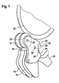
- an open slaughtered animal 10 can be seen in section with a spinal column 12, to which the inner guiding device 14 is aligned, which rests against the spine 12 in the interior of the slaughtered animal 10 in the region of the spinal column 12.
- an outer guide device On the outside in the region of the spinal column 12, an outer guide device, not shown, is arranged, which may correspond to the invention. However, it is also possible to use as an outer guide device such that can be found in the prior art or the documents mentioned above.
- the inner guide device 14, referred to below as a carriage comprises, as mentioned, two mutually spaced runners 16, 18 and rollers 21, 23 (FIG. Fig. 1 . 6, 7 ).
- the clear distance a of the skids 16, 18 or rollers 21, 23 should be in the range between 25 mm and 40 mm, so that a support in the region of the longitudinal side edges of the spine 12 is possible, thus the inwardly directed projection 20 of the spine 12th between the runners 16,18 and rollers 21, 23 extends, whereby the desired guidance is ensured.
- the carriage 14 is associated with a cutting member such as circular saw blade 22, as is apparent from the Fig. 1 and 6 results. This may extend in sections in the upper area between the runners, like the Fig. 6 purely in principle clarified. Thus, when splitting the rollers 21, 23 run in front of the runners 16, 18th
- any design is understood below, with which an at least line-shaped - if necessary, interrupted line-shaped - concerns in the spinal column area of the slaughtered animal takes place.
- the runners can consist of a plate-shaped base element with an attached round iron or a disc element with rounded edges. Other constructive possibilities are also given. In that regard, the explanation of the embodiments is not to be understood as limiting the scope of protection.
- the carriage 14 has two plate-shaped elements 24, 26, the outer edges of the spinal column are rounded or have essays, as will be described below.
- the plate-shaped elements 24, 26 are in turn of plate-shaped support members 28, 30, which are connected to a holder 32, which are adjusted by a handling device, not shown together with the circular saw blade 22 and vertically along the spine 12 for splitting this procedure.
- the carriage 14 is pivotable about the holder 32 about an axis 34.
- the axis 34 extends from the holder 32 and passes through the support elements 28, 30.
- a pin 36 is provided, which is positioned fixed to the holder 32 and the pivotal movement of the carriage 14 about the axis 34 limits.
- the support elements 28, 30 on the back a recess 38 with stops 40, 42, which limit the pivoting movement.
- Fig. 1 illustrates, of the support members 28, 30 each have a roller member 21, 23 which is rotatable about an axis 25 which is parallel to the axis 34 about which the support members 28, 30 and thus the plate-shaped runner elements 24, 26 and the roller elements 21, 23 are pivotable together to the holder 32.
- the area of the plate-shaped elements 24, 26 which can be applied to the slaughter animal 10 in the region of the spine 12 is referred to below as a skid, irrespective of whether this is a rounded edge of the preferably stainless steel element 24 , 26 or an essay in the form of z.
- a curved bar iron or another design or construction is provided which allows the guiding function of the carriage 14 along the spine 20 in or on the slaughtered animal 10.
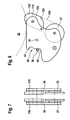
- the runner element 44 has a plate-shaped as a carrier body 50 designated element, which has a trapezoid geometry in side view together with Schlmanier practitioner running skid 52. In this case, the runner 52 extends along the short base.
- the skid 52 is basically composed of three sections, namely a first outer section 54, a middle section 56 and a further outer section 58.
- the first outer section 54 is oriented downwards in use, ie the second outer section 58 facing the saw blade 22.
- the first outer portion 54 follows an arc with an outer radius R a of z. B. 45 mm.
- the arcuate profile merges on the outside into a tangentially continuing section 56 of the carrier body 50.
- this region 58 can also be formed by the runner 52.
- the second outer portion 58 should preferably have a same radius of curvature R a as the first outer portion 54, wherein the arc can extend over an angle of 90 °.
- the curved course of the first outer portion 54 can be made smaller, z. B. 60 ° to 70 °.
- the lengths of the outer portions 54, 58 as viewed along the longer base 62 of the carrier body 50 should be the same. As preferred values are z. B. 40 mm to 60 mm.
- the middle section 56 running between the outer sections 54, 58, whose longitudinal extent along the length base 62 can be in the range between 130 mm and 170 mm, has in the exemplary embodiment of FIG Fig. 2 a straight course and is continuous in the outer sections 54, 58 over.
- the middle section 56 thus represents a tangential extension of the inner ends of the outer sections 54, 58.
- the runner element 46 has a similar shape as the runner element 44 with the restriction that, in addition to roughly geometrically identically formed outer sections 54, 58, the middle section 64 of the runner extending therebetween exhibits a curved concave course.
- the radius of curvature R i1 of the outside of the portion 64 may be in the range between 450 mm and 550 mm.
- the runner element 48 according to Fig. 4 differs in the outer portions 54, 56 of the runner elements 44, 46 of the FIGS. 2 and 3 basically not, so that the same reference numerals are used.
- the middle portion 66 of the skid is deviated to be composed of an inner portion 68 and adjacent rectilinear end portions 70, 72.
- the inner portion 68 may along the base leg 62 of the support body 50 of the runner member 48 has a length of z. B. 140 mm to 160 mm.
- the extent of the inner portion 68 should be in the range between 90 mm and 110 mm.
- the symmetrically to the inner portion 68 extending end portions 70, 72 thus have lengths of 20 mm to 25 mm, with the same longitudinal extent of the support body 50 according to the embodiments of FIGS. 2 and 3 ,
- the radius of curvature of the inner portion 68 should correspond to that of the outer portions 54, 58, ie the outer effective radius of curvature R i2 corresponds to R A.
- roller elements 21, 23 are provided which are rotatable about the axis 25 which is parallel to the axis of the separating member 22. Furthermore, the roller elements 21, 23 are arranged in front of the runner elements 116, 118 with respect to the splitting direction of the slaughter animal 10, consequently preceding them.
- the clear effective width of the roller elements 21, 23 should be that of the runner elements 116, 118 in the area in which they rest against the slaughtered animal 10.
- the combination of the guide rollers 21, 23 with the sliding guide via the runners 116, 118 results in an optimal alignment of the spinal column area of the slaughtered animal 10 with the separating element 22.
- the runner elements 116, 118 have a wedge-like geometry in side view, wherein the first outer section 120 following a circular arc section and the second likewise an arcuate portion following outer portion 122 preferably have a same radius of curvature, which should be in the range between 30 mm and 40 mm. Between the outer portions 120, 122 extends a central portion 124 which merges continuously into the outer portions 120, 122 and extends in a straight line. In this case, the runner elements 116, 118 are aligned with respect to the central portion 124 such that it extends in extension of a tangent 126 which extends from the periphery of the respective roller element 21, 23. The length of the middle section 124 should be in the range of 20 mm to 40 mm.
- the length of the outer portions 120, 122, which follow a circular arc and the central portion 124 viewed in projection on a straight line in which the central portion 124 is located preferably amounts to between 80 mm and 100 mm, without thereby limiting the teaching of the invention becomes.
- the runner elements 116, 118 and the upstream roller elements 21, 23 each go from a plate-shaped support member, which is the Fig. 1 corresponds, so that the same reference numerals are used.
- the support members 28, 30 form a unit which is pivotable about the axis 34, as in connection with the Fig. 1 has been explained.
- Kufenabgewandt the support members 28, 30 each have a recess 38 which is limited by stops 40, 42. In the recess 38 engages an outgoing from the holder 32 counter stop as pin 36, so that the pivotal movement of the support members 28, 30 and thus the runner elements 116, 118 and the roller elements 121, 123 is limited.
Landscapes
- Life Sciences & Earth Sciences (AREA)
- Engineering & Computer Science (AREA)
- Food Science & Technology (AREA)
- Processing Of Meat And Fish (AREA)
- Catching Or Destruction (AREA)
Applications Claiming Priority (2)
| Application Number | Priority Date | Filing Date | Title |
|---|---|---|---|
| DE202008000054 | 2008-05-09 | ||
| DE202008008813U DE202008008813U1 (de) | 2008-05-09 | 2008-08-14 | Anordnung zum Spalten eines Schlachttieres |
Publications (2)
| Publication Number | Publication Date |
|---|---|
| EP2116134A1 true EP2116134A1 (fr) | 2009-11-11 |
| EP2116134B1 EP2116134B1 (fr) | 2018-07-04 |
Family
ID=39869252
Family Applications (1)
| Application Number | Title | Priority Date | Filing Date |
|---|---|---|---|
| EP09159816.9A Not-in-force EP2116134B1 (fr) | 2008-05-09 | 2009-05-08 | Agencement de fendage d'un animal d'abattage |
Country Status (4)
| Country | Link |
|---|---|
| EP (1) | EP2116134B1 (fr) |
| DE (1) | DE202008008813U1 (fr) |
| DK (1) | DK2116134T3 (fr) |
| ES (1) | ES2689728T3 (fr) |
Citations (11)
| Publication number | Priority date | Publication date | Assignee | Title |
|---|---|---|---|---|
| US637490A (en) | 1899-01-17 | 1899-11-21 | Wallace G Tower | Beef-splitting machine. |
| DE1817274A1 (de) | 1968-01-04 | 1969-07-31 | Kontrollhudar Andelslakteriern | Spaltvorrichtung fuer Schlachtvieh |
| FR2535944A1 (fr) | 1982-11-15 | 1984-05-18 | Schlumberger Cie N | Machine automatique a fendre les animaux de boucherie, notamment les porcs |
| FR2573625A1 (fr) * | 1984-11-29 | 1986-05-30 | Schlumberger Cie N | Dispositif de guidage interieur de la colonne vertebrale pour la fente des animaux de boucherie |
| FR2576183A1 (fr) | 1985-01-24 | 1986-07-25 | Schlumberger Cie N | Dispositif de guidage de la colonne vertebrale pour la fente automatique d'animaux de boucherie |
| US4667368A (en) | 1984-11-29 | 1987-05-26 | N. Schlumberger & Cie | Backbone inner guiding device for splitting butchery animals |
| EP0801900A1 (fr) * | 1996-04-18 | 1997-10-22 | DURAND INTERNATIONAL (société anonyme) | Procédé et dispositif de guidage dorsal pour la fente d'une carcasse d'animal de boucherie |
| WO2003028469A1 (fr) | 2001-10-03 | 2003-04-10 | Sfk-Danfotech A/S | Moyen de commande d'appareil destine a decouper des animaux abbatus selon leur plan de symetrie |
| DE69622762T2 (de) | 1995-05-05 | 2003-04-24 | Sfk-Danfotech A/S, Aalborg | Vorrichtung zum zerteilen der wirbelsäule eines schlachttierkörpers in zwei hälften entlang der symmetrieachse |
| DE60100042T2 (de) | 2000-02-18 | 2003-07-17 | Durand International, Chomerac | Vorrichtung zum Spalten mit einem beweglichen Stand |
| DE60100277T2 (de) | 2000-02-18 | 2004-04-01 | Durand International | Vorrichtung zum Spalten von Schlachttierkörpern, Anlage zum Spalten von Schlachttierkörpern mit solcher Vorrichtung und Verfahren zum Spalten von Schlachttierkörpern |
-
2008
- 2008-08-14 DE DE202008008813U patent/DE202008008813U1/de not_active Expired - Lifetime
-
2009
- 2009-05-08 DK DK09159816.9T patent/DK2116134T3/en active
- 2009-05-08 ES ES09159816.9T patent/ES2689728T3/es active Active
- 2009-05-08 EP EP09159816.9A patent/EP2116134B1/fr not_active Not-in-force
Patent Citations (12)
| Publication number | Priority date | Publication date | Assignee | Title |
|---|---|---|---|---|
| US637490A (en) | 1899-01-17 | 1899-11-21 | Wallace G Tower | Beef-splitting machine. |
| DE1817274A1 (de) | 1968-01-04 | 1969-07-31 | Kontrollhudar Andelslakteriern | Spaltvorrichtung fuer Schlachtvieh |
| FR2535944A1 (fr) | 1982-11-15 | 1984-05-18 | Schlumberger Cie N | Machine automatique a fendre les animaux de boucherie, notamment les porcs |
| FR2573625A1 (fr) * | 1984-11-29 | 1986-05-30 | Schlumberger Cie N | Dispositif de guidage interieur de la colonne vertebrale pour la fente des animaux de boucherie |
| US4667368A (en) | 1984-11-29 | 1987-05-26 | N. Schlumberger & Cie | Backbone inner guiding device for splitting butchery animals |
| FR2576183A1 (fr) | 1985-01-24 | 1986-07-25 | Schlumberger Cie N | Dispositif de guidage de la colonne vertebrale pour la fente automatique d'animaux de boucherie |
| DE69622762T2 (de) | 1995-05-05 | 2003-04-24 | Sfk-Danfotech A/S, Aalborg | Vorrichtung zum zerteilen der wirbelsäule eines schlachttierkörpers in zwei hälften entlang der symmetrieachse |
| EP0801900A1 (fr) * | 1996-04-18 | 1997-10-22 | DURAND INTERNATIONAL (société anonyme) | Procédé et dispositif de guidage dorsal pour la fente d'une carcasse d'animal de boucherie |
| EP0801900B1 (fr) | 1996-04-18 | 2002-07-17 | DURAND INTERNATIONAL (société anonyme) | Procédé et dispositif de guidage dorsal pour la fente d'une carcasse d'animal de boucherie |
| DE60100042T2 (de) | 2000-02-18 | 2003-07-17 | Durand International, Chomerac | Vorrichtung zum Spalten mit einem beweglichen Stand |
| DE60100277T2 (de) | 2000-02-18 | 2004-04-01 | Durand International | Vorrichtung zum Spalten von Schlachttierkörpern, Anlage zum Spalten von Schlachttierkörpern mit solcher Vorrichtung und Verfahren zum Spalten von Schlachttierkörpern |
| WO2003028469A1 (fr) | 2001-10-03 | 2003-04-10 | Sfk-Danfotech A/S | Moyen de commande d'appareil destine a decouper des animaux abbatus selon leur plan de symetrie |
Also Published As
| Publication number | Publication date |
|---|---|
| EP2116134B1 (fr) | 2018-07-04 |
| ES2689728T3 (es) | 2018-11-15 |
| DK2116134T3 (en) | 2018-10-22 |
| DE202008008813U1 (de) | 2008-10-16 |
Similar Documents
| Publication | Publication Date | Title |
|---|---|---|
| DE69902314T2 (de) | Zange mit ergonomischen Griffen | |
| DE3332022C2 (fr) | ||
| DE2600766C2 (fr) | ||
| DE60301908T2 (de) | Externes Fixationssystem zur Versorgung von Knochenbrüchen | |
| EP0720817B1 (fr) | Dispositif pour le découpage des ailes de volailles | |
| EP0429035B1 (fr) | Couteau à mitre en matériau sintré | |
| DE4304781C1 (de) | Verfahren zum Abtrennen der Flügel von Geflügelkörpern | |
| DE69000414T2 (de) | Einstellbare innere fuehrungseinrichtung fuer eine vorrichtung zum zerschneiden des gerippes von schlachttieren und verfahren fuer dieses zerschneiden. | |
| DE3433685A1 (de) | Vorrichtung zum entgraten von werkstuecken | |
| DE69917718T2 (de) | Verfahren und Vorrichtung zum Längsschneiden von Karkassenhälften | |
| DE60220670T2 (de) | Schlachttierkörperausrichtungssystem für vorrichtung zum zerteilen von schlachttierkörpern | |
| EP2116134B1 (fr) | Agencement de fendage d'un animal d'abattage | |
| CH674327A5 (fr) | ||
| DE102007017562B3 (de) | Klinge, Klingenhalter mit der Klinge und Verfahren zum Abziehen einer Verbindungsnaht mittels des Klingenhalters | |
| DE3332369C2 (de) | Feilenführung für eine Sägekette | |
| DE1552612C3 (de) | Schneidemaschine für Stabmateria] | |
| EP1245352B1 (fr) | Rabot refendeur à main destiné aux courroies | |
| DE3340842C2 (de) | Sägemaschine | |
| DE3413250A1 (de) | Klemmvorrichtung fuer ein schneidmesser eines mikrotomes | |
| DE60100277T2 (de) | Vorrichtung zum Spalten von Schlachttierkörpern, Anlage zum Spalten von Schlachttierkörpern mit solcher Vorrichtung und Verfahren zum Spalten von Schlachttierkörpern | |
| DE3319261A1 (de) | Spaltsaege zum spalten von geschlachteten tieren | |
| EP1979543B1 (fr) | Dispositif et procede pour reprofiler le rail d'une voie | |
| DE10202861C1 (de) | Messer für Kotelettschneider und Vorrichtung zum Ausschälen eines Kotelettstranges | |
| DE3540507A1 (de) | Stichsaege, insbesondere zum zerteilen von fleisch | |
| EP3406400B1 (fr) | Procédé et affûteuse destinée à l'affûtage des couteaux |
Legal Events
| Date | Code | Title | Description |
|---|---|---|---|
| PUAI | Public reference made under article 153(3) epc to a published international application that has entered the european phase |
Free format text: ORIGINAL CODE: 0009012 |
|
| AK | Designated contracting states |
Kind code of ref document: A1 Designated state(s): AT BE BG CH CY CZ DE DK EE ES FI FR GB GR HR HU IE IS IT LI LT LU LV MC MK MT NL NO PL PT RO SE SI SK TR |
|
| 17P | Request for examination filed |
Effective date: 20091030 |
|
| 17Q | First examination report despatched |
Effective date: 20130524 |
|
| GRAP | Despatch of communication of intention to grant a patent |
Free format text: ORIGINAL CODE: EPIDOSNIGR1 |
|
| STAA | Information on the status of an ep patent application or granted ep patent |
Free format text: STATUS: GRANT OF PATENT IS INTENDED |
|
| INTG | Intention to grant announced |
Effective date: 20171018 |
|
| GRAS | Grant fee paid |
Free format text: ORIGINAL CODE: EPIDOSNIGR3 |
|
| GRAJ | Information related to disapproval of communication of intention to grant by the applicant or resumption of examination proceedings by the epo deleted |
Free format text: ORIGINAL CODE: EPIDOSDIGR1 |
|
| GRAL | Information related to payment of fee for publishing/printing deleted |
Free format text: ORIGINAL CODE: EPIDOSDIGR3 |
|
| STAA | Information on the status of an ep patent application or granted ep patent |
Free format text: STATUS: EXAMINATION IS IN PROGRESS |
|
| GRAP | Despatch of communication of intention to grant a patent |
Free format text: ORIGINAL CODE: EPIDOSNIGR1 |
|
| STAA | Information on the status of an ep patent application or granted ep patent |
Free format text: STATUS: GRANT OF PATENT IS INTENDED |
|
| INTC | Intention to grant announced (deleted) | ||
| INTG | Intention to grant announced |
Effective date: 20180323 |
|
| GRAA | (expected) grant |
Free format text: ORIGINAL CODE: 0009210 |
|
| STAA | Information on the status of an ep patent application or granted ep patent |
Free format text: STATUS: THE PATENT HAS BEEN GRANTED |
|
| AK | Designated contracting states |
Kind code of ref document: B1 Designated state(s): AT BE BG CH CY CZ DE DK EE ES FI FR GB GR HR HU IE IS IT LI LT LU LV MC MK MT NL NO PL PT RO SE SI SK TR |
|
| REG | Reference to a national code |
Ref country code: GB Ref legal event code: FG4D Free format text: NOT ENGLISH |
|
| REG | Reference to a national code |
Ref country code: CH Ref legal event code: EP |
|
| REG | Reference to a national code |
Ref country code: AT Ref legal event code: REF Ref document number: 1013534 Country of ref document: AT Kind code of ref document: T Effective date: 20180715 |
|
| REG | Reference to a national code |
Ref country code: IE Ref legal event code: FG4D Free format text: LANGUAGE OF EP DOCUMENT: GERMAN |
|
| REG | Reference to a national code |
Ref country code: DE Ref legal event code: R096 Ref document number: 502009015062 Country of ref document: DE |
|
| REG | Reference to a national code |
Ref country code: NL Ref legal event code: FP |
|
| REG | Reference to a national code |
Ref country code: DK Ref legal event code: T3 Effective date: 20181015 |
|
| REG | Reference to a national code |
Ref country code: ES Ref legal event code: FG2A Ref document number: 2689728 Country of ref document: ES Kind code of ref document: T3 Effective date: 20181115 |
|
| REG | Reference to a national code |
Ref country code: LT Ref legal event code: MG4D |
|
| PG25 | Lapsed in a contracting state [announced via postgrant information from national office to epo] |
Ref country code: BG Free format text: LAPSE BECAUSE OF FAILURE TO SUBMIT A TRANSLATION OF THE DESCRIPTION OR TO PAY THE FEE WITHIN THE PRESCRIBED TIME-LIMIT Effective date: 20181004 Ref country code: SE Free format text: LAPSE BECAUSE OF FAILURE TO SUBMIT A TRANSLATION OF THE DESCRIPTION OR TO PAY THE FEE WITHIN THE PRESCRIBED TIME-LIMIT Effective date: 20180704 Ref country code: PL Free format text: LAPSE BECAUSE OF FAILURE TO SUBMIT A TRANSLATION OF THE DESCRIPTION OR TO PAY THE FEE WITHIN THE PRESCRIBED TIME-LIMIT Effective date: 20180704 Ref country code: LT Free format text: LAPSE BECAUSE OF FAILURE TO SUBMIT A TRANSLATION OF THE DESCRIPTION OR TO PAY THE FEE WITHIN THE PRESCRIBED TIME-LIMIT Effective date: 20180704 Ref country code: FI Free format text: LAPSE BECAUSE OF FAILURE TO SUBMIT A TRANSLATION OF THE DESCRIPTION OR TO PAY THE FEE WITHIN THE PRESCRIBED TIME-LIMIT Effective date: 20180704 Ref country code: NO Free format text: LAPSE BECAUSE OF FAILURE TO SUBMIT A TRANSLATION OF THE DESCRIPTION OR TO PAY THE FEE WITHIN THE PRESCRIBED TIME-LIMIT Effective date: 20181004 Ref country code: GR Free format text: LAPSE BECAUSE OF FAILURE TO SUBMIT A TRANSLATION OF THE DESCRIPTION OR TO PAY THE FEE WITHIN THE PRESCRIBED TIME-LIMIT Effective date: 20181005 Ref country code: CZ Free format text: LAPSE BECAUSE OF FAILURE TO SUBMIT A TRANSLATION OF THE DESCRIPTION OR TO PAY THE FEE WITHIN THE PRESCRIBED TIME-LIMIT Effective date: 20180704 |
|
| PG25 | Lapsed in a contracting state [announced via postgrant information from national office to epo] |
Ref country code: HR Free format text: LAPSE BECAUSE OF FAILURE TO SUBMIT A TRANSLATION OF THE DESCRIPTION OR TO PAY THE FEE WITHIN THE PRESCRIBED TIME-LIMIT Effective date: 20180704 Ref country code: LV Free format text: LAPSE BECAUSE OF FAILURE TO SUBMIT A TRANSLATION OF THE DESCRIPTION OR TO PAY THE FEE WITHIN THE PRESCRIBED TIME-LIMIT Effective date: 20180704 |
|
| REG | Reference to a national code |
Ref country code: DE Ref legal event code: R097 Ref document number: 502009015062 Country of ref document: DE |
|
| PG25 | Lapsed in a contracting state [announced via postgrant information from national office to epo] |
Ref country code: IT Free format text: LAPSE BECAUSE OF FAILURE TO SUBMIT A TRANSLATION OF THE DESCRIPTION OR TO PAY THE FEE WITHIN THE PRESCRIBED TIME-LIMIT Effective date: 20180704 Ref country code: EE Free format text: LAPSE BECAUSE OF FAILURE TO SUBMIT A TRANSLATION OF THE DESCRIPTION OR TO PAY THE FEE WITHIN THE PRESCRIBED TIME-LIMIT Effective date: 20180704 Ref country code: RO Free format text: LAPSE BECAUSE OF FAILURE TO SUBMIT A TRANSLATION OF THE DESCRIPTION OR TO PAY THE FEE WITHIN THE PRESCRIBED TIME-LIMIT Effective date: 20180704 |
|
| PLBE | No opposition filed within time limit |
Free format text: ORIGINAL CODE: 0009261 |
|
| STAA | Information on the status of an ep patent application or granted ep patent |
Free format text: STATUS: NO OPPOSITION FILED WITHIN TIME LIMIT |
|
| PG25 | Lapsed in a contracting state [announced via postgrant information from national office to epo] |
Ref country code: SK Free format text: LAPSE BECAUSE OF FAILURE TO SUBMIT A TRANSLATION OF THE DESCRIPTION OR TO PAY THE FEE WITHIN THE PRESCRIBED TIME-LIMIT Effective date: 20180704 |
|
| 26N | No opposition filed |
Effective date: 20190405 |
|
| PG25 | Lapsed in a contracting state [announced via postgrant information from national office to epo] |
Ref country code: SI Free format text: LAPSE BECAUSE OF FAILURE TO SUBMIT A TRANSLATION OF THE DESCRIPTION OR TO PAY THE FEE WITHIN THE PRESCRIBED TIME-LIMIT Effective date: 20180704 |
|
| PGFP | Annual fee paid to national office [announced via postgrant information from national office to epo] |
Ref country code: FR Payment date: 20190523 Year of fee payment: 11 |
|
| REG | Reference to a national code |
Ref country code: CH Ref legal event code: PL |
|
| GBPC | Gb: european patent ceased through non-payment of renewal fee |
Effective date: 20190508 |
|
| PG25 | Lapsed in a contracting state [announced via postgrant information from national office to epo] |
Ref country code: LI Free format text: LAPSE BECAUSE OF NON-PAYMENT OF DUE FEES Effective date: 20190531 Ref country code: CH Free format text: LAPSE BECAUSE OF NON-PAYMENT OF DUE FEES Effective date: 20190531 Ref country code: MC Free format text: LAPSE BECAUSE OF FAILURE TO SUBMIT A TRANSLATION OF THE DESCRIPTION OR TO PAY THE FEE WITHIN THE PRESCRIBED TIME-LIMIT Effective date: 20180704 |
|
| REG | Reference to a national code |
Ref country code: BE Ref legal event code: MM Effective date: 20190531 |
|
| PG25 | Lapsed in a contracting state [announced via postgrant information from national office to epo] |
Ref country code: LU Free format text: LAPSE BECAUSE OF NON-PAYMENT OF DUE FEES Effective date: 20190508 |
|
| PG25 | Lapsed in a contracting state [announced via postgrant information from national office to epo] |
Ref country code: TR Free format text: LAPSE BECAUSE OF FAILURE TO SUBMIT A TRANSLATION OF THE DESCRIPTION OR TO PAY THE FEE WITHIN THE PRESCRIBED TIME-LIMIT Effective date: 20180704 |
|
| PG25 | Lapsed in a contracting state [announced via postgrant information from national office to epo] |
Ref country code: IE Free format text: LAPSE BECAUSE OF NON-PAYMENT OF DUE FEES Effective date: 20190508 Ref country code: GB Free format text: LAPSE BECAUSE OF NON-PAYMENT OF DUE FEES Effective date: 20190508 |
|
| PG25 | Lapsed in a contracting state [announced via postgrant information from national office to epo] |
Ref country code: BE Free format text: LAPSE BECAUSE OF NON-PAYMENT OF DUE FEES Effective date: 20190531 |
|
| PG25 | Lapsed in a contracting state [announced via postgrant information from national office to epo] |
Ref country code: PT Free format text: LAPSE BECAUSE OF FAILURE TO SUBMIT A TRANSLATION OF THE DESCRIPTION OR TO PAY THE FEE WITHIN THE PRESCRIBED TIME-LIMIT Effective date: 20181105 |
|
| REG | Reference to a national code |
Ref country code: AT Ref legal event code: MM01 Ref document number: 1013534 Country of ref document: AT Kind code of ref document: T Effective date: 20190508 |
|
| PG25 | Lapsed in a contracting state [announced via postgrant information from national office to epo] |
Ref country code: AT Free format text: LAPSE BECAUSE OF NON-PAYMENT OF DUE FEES Effective date: 20190508 |
|
| PG25 | Lapsed in a contracting state [announced via postgrant information from national office to epo] |
Ref country code: FR Free format text: LAPSE BECAUSE OF NON-PAYMENT OF DUE FEES Effective date: 20200531 |
|
| PG25 | Lapsed in a contracting state [announced via postgrant information from national office to epo] |
Ref country code: CY Free format text: LAPSE BECAUSE OF FAILURE TO SUBMIT A TRANSLATION OF THE DESCRIPTION OR TO PAY THE FEE WITHIN THE PRESCRIBED TIME-LIMIT Effective date: 20180704 |
|
| PG25 | Lapsed in a contracting state [announced via postgrant information from national office to epo] |
Ref country code: MT Free format text: LAPSE BECAUSE OF FAILURE TO SUBMIT A TRANSLATION OF THE DESCRIPTION OR TO PAY THE FEE WITHIN THE PRESCRIBED TIME-LIMIT Effective date: 20180704 Ref country code: HU Free format text: LAPSE BECAUSE OF FAILURE TO SUBMIT A TRANSLATION OF THE DESCRIPTION OR TO PAY THE FEE WITHIN THE PRESCRIBED TIME-LIMIT; INVALID AB INITIO Effective date: 20090508 |
|
| PGFP | Annual fee paid to national office [announced via postgrant information from national office to epo] |
Ref country code: NL Payment date: 20210519 Year of fee payment: 13 Ref country code: DE Payment date: 20210504 Year of fee payment: 13 |
|
| PGFP | Annual fee paid to national office [announced via postgrant information from national office to epo] |
Ref country code: DK Payment date: 20210521 Year of fee payment: 13 |
|
| PGFP | Annual fee paid to national office [announced via postgrant information from national office to epo] |
Ref country code: IS Payment date: 20210511 Year of fee payment: 13 |
|
| PGFP | Annual fee paid to national office [announced via postgrant information from national office to epo] |
Ref country code: ES Payment date: 20210721 Year of fee payment: 13 |
|
| PG25 | Lapsed in a contracting state [announced via postgrant information from national office to epo] |
Ref country code: MK Free format text: LAPSE BECAUSE OF FAILURE TO SUBMIT A TRANSLATION OF THE DESCRIPTION OR TO PAY THE FEE WITHIN THE PRESCRIBED TIME-LIMIT Effective date: 20180704 |
|
| REG | Reference to a national code |
Ref country code: DE Ref legal event code: R119 Ref document number: 502009015062 Country of ref document: DE |
|
| REG | Reference to a national code |
Ref country code: DK Ref legal event code: EBP Effective date: 20220531 |
|
| REG | Reference to a national code |
Ref country code: NL Ref legal event code: MM Effective date: 20220601 |
|
| PG25 | Lapsed in a contracting state [announced via postgrant information from national office to epo] |
Ref country code: DK Free format text: LAPSE BECAUSE OF NON-PAYMENT OF DUE FEES Effective date: 20220531 |
|
| PG25 | Lapsed in a contracting state [announced via postgrant information from national office to epo] |
Ref country code: DE Free format text: LAPSE BECAUSE OF NON-PAYMENT OF DUE FEES Effective date: 20221201 |
|
| REG | Reference to a national code |
Ref country code: ES Ref legal event code: FD2A Effective date: 20230628 |
|
| PG25 | Lapsed in a contracting state [announced via postgrant information from national office to epo] |
Ref country code: NL Free format text: LAPSE BECAUSE OF NON-PAYMENT OF DUE FEES Effective date: 20220601 |
|
| PG25 | Lapsed in a contracting state [announced via postgrant information from national office to epo] |
Ref country code: ES Free format text: LAPSE BECAUSE OF NON-PAYMENT OF DUE FEES Effective date: 20220509 |
|
| PG25 | Lapsed in a contracting state [announced via postgrant information from national office to epo] |
Ref country code: IS Free format text: LAPSE BECAUSE OF NON-PAYMENT OF DUE FEES Effective date: 20221205 |