EP2116756A1 - Lighting device - Google Patents
Lighting device Download PDFInfo
- Publication number
- EP2116756A1 EP2116756A1 EP09159743A EP09159743A EP2116756A1 EP 2116756 A1 EP2116756 A1 EP 2116756A1 EP 09159743 A EP09159743 A EP 09159743A EP 09159743 A EP09159743 A EP 09159743A EP 2116756 A1 EP2116756 A1 EP 2116756A1
- Authority
- EP
- European Patent Office
- Prior art keywords
- lighting device
- mounting
- light sources
- reflector
- arms
- Prior art date
- Legal status (The legal status is an assumption and is not a legal conclusion. Google has not performed a legal analysis and makes no representation as to the accuracy of the status listed.)
- Granted
Links
- 239000000463 material Substances 0.000 claims description 12
- 239000004411 aluminium Substances 0.000 claims description 9
- 229910052782 aluminium Inorganic materials 0.000 claims description 9
- XAGFODPZIPBFFR-UHFFFAOYSA-N aluminium Chemical compound [Al] XAGFODPZIPBFFR-UHFFFAOYSA-N 0.000 claims description 9
- 238000004512 die casting Methods 0.000 claims description 4
- 239000004033 plastic Substances 0.000 claims description 4
- 239000012809 cooling fluid Substances 0.000 claims description 3
- 239000002344 surface layer Substances 0.000 claims 1
- 238000005265 energy consumption Methods 0.000 abstract description 7
- 238000005286 illumination Methods 0.000 abstract description 4
- 230000003287 optical effect Effects 0.000 description 11
- 230000004907 flux Effects 0.000 description 8
- XUIMIQQOPSSXEZ-UHFFFAOYSA-N Silicon Chemical compound [Si] XUIMIQQOPSSXEZ-UHFFFAOYSA-N 0.000 description 3
- 238000000034 method Methods 0.000 description 3
- 239000004417 polycarbonate Substances 0.000 description 3
- 229920000515 polycarbonate Polymers 0.000 description 3
- 230000008569 process Effects 0.000 description 3
- 230000009467 reduction Effects 0.000 description 3
- 229910052710 silicon Inorganic materials 0.000 description 3
- 239000010703 silicon Substances 0.000 description 3
- 238000001771 vacuum deposition Methods 0.000 description 3
- DGAQECJNVWCQMB-PUAWFVPOSA-M Ilexoside XXIX Chemical compound C[C@@H]1CC[C@@]2(CC[C@@]3(C(=CC[C@H]4[C@]3(CC[C@@H]5[C@@]4(CC[C@@H](C5(C)C)OS(=O)(=O)[O-])C)C)[C@@H]2[C@]1(C)O)C)C(=O)O[C@H]6[C@@H]([C@H]([C@@H]([C@H](O6)CO)O)O)O.[Na+] DGAQECJNVWCQMB-PUAWFVPOSA-M 0.000 description 2
- 230000015556 catabolic process Effects 0.000 description 2
- 238000006731 degradation reaction Methods 0.000 description 2
- 239000005431 greenhouse gas Substances 0.000 description 2
- QSHDDOUJBYECFT-UHFFFAOYSA-N mercury Chemical compound [Hg] QSHDDOUJBYECFT-UHFFFAOYSA-N 0.000 description 2
- 229910052753 mercury Inorganic materials 0.000 description 2
- 229910001511 metal iodide Inorganic materials 0.000 description 2
- 229910052708 sodium Inorganic materials 0.000 description 2
- 239000011734 sodium Substances 0.000 description 2
- 238000012360 testing method Methods 0.000 description 2
- 230000009471 action Effects 0.000 description 1
- 230000003466 anti-cipated effect Effects 0.000 description 1
- 238000006243 chemical reaction Methods 0.000 description 1
- 238000013461 design Methods 0.000 description 1
- 238000011161 development Methods 0.000 description 1
- 239000006185 dispersion Substances 0.000 description 1
- 238000005516 engineering process Methods 0.000 description 1
- 230000005923 long-lasting effect Effects 0.000 description 1
- 238000004519 manufacturing process Methods 0.000 description 1
- 238000012986 modification Methods 0.000 description 1
- 230000004048 modification Effects 0.000 description 1
- 238000005215 recombination Methods 0.000 description 1
- 230000006798 recombination Effects 0.000 description 1
- 239000004065 semiconductor Substances 0.000 description 1
- 239000002470 thermal conductor Substances 0.000 description 1
Images



Classifications
-
- F—MECHANICAL ENGINEERING; LIGHTING; HEATING; WEAPONS; BLASTING
- F21—LIGHTING
- F21V—FUNCTIONAL FEATURES OR DETAILS OF LIGHTING DEVICES OR SYSTEMS THEREOF; STRUCTURAL COMBINATIONS OF LIGHTING DEVICES WITH OTHER ARTICLES, NOT OTHERWISE PROVIDED FOR
- F21V7/00—Reflectors for light sources
- F21V7/0058—Reflectors for light sources adapted to cooperate with light sources of shapes different from point-like or linear, e.g. circular light sources
-
- F—MECHANICAL ENGINEERING; LIGHTING; HEATING; WEAPONS; BLASTING
- F21—LIGHTING
- F21K—NON-ELECTRIC LIGHT SOURCES USING LUMINESCENCE; LIGHT SOURCES USING ELECTROCHEMILUMINESCENCE; LIGHT SOURCES USING CHARGES OF COMBUSTIBLE MATERIAL; LIGHT SOURCES USING SEMICONDUCTOR DEVICES AS LIGHT-GENERATING ELEMENTS; LIGHT SOURCES NOT OTHERWISE PROVIDED FOR
- F21K9/00—Light sources using semiconductor devices as light-generating elements, e.g. using light-emitting diodes [LED] or lasers
- F21K9/60—Optical arrangements integrated in the light source, e.g. for improving the colour rendering index or the light extraction
- F21K9/68—Details of reflectors forming part of the light source
-
- F—MECHANICAL ENGINEERING; LIGHTING; HEATING; WEAPONS; BLASTING
- F21—LIGHTING
- F21V—FUNCTIONAL FEATURES OR DETAILS OF LIGHTING DEVICES OR SYSTEMS THEREOF; STRUCTURAL COMBINATIONS OF LIGHTING DEVICES WITH OTHER ARTICLES, NOT OTHERWISE PROVIDED FOR
- F21V29/00—Protecting lighting devices from thermal damage; Cooling or heating arrangements specially adapted for lighting devices or systems
- F21V29/50—Cooling arrangements
- F21V29/56—Cooling arrangements using liquid coolants
-
- F—MECHANICAL ENGINEERING; LIGHTING; HEATING; WEAPONS; BLASTING
- F21—LIGHTING
- F21W—INDEXING SCHEME ASSOCIATED WITH SUBCLASSES F21K, F21L, F21S and F21V, RELATING TO USES OR APPLICATIONS OF LIGHTING DEVICES OR SYSTEMS
- F21W2111/00—Use or application of lighting devices or systems for signalling, marking or indicating, not provided for in codes F21W2102/00 – F21W2107/00
- F21W2111/06—Use or application of lighting devices or systems for signalling, marking or indicating, not provided for in codes F21W2102/00 – F21W2107/00 for aircraft runways or the like
-
- F—MECHANICAL ENGINEERING; LIGHTING; HEATING; WEAPONS; BLASTING
- F21—LIGHTING
- F21W—INDEXING SCHEME ASSOCIATED WITH SUBCLASSES F21K, F21L, F21S and F21V, RELATING TO USES OR APPLICATIONS OF LIGHTING DEVICES OR SYSTEMS
- F21W2131/00—Use or application of lighting devices or systems not provided for in codes F21W2102/00-F21W2121/00
- F21W2131/10—Outdoor lighting
- F21W2131/103—Outdoor lighting of streets or roads
-
- F—MECHANICAL ENGINEERING; LIGHTING; HEATING; WEAPONS; BLASTING
- F21—LIGHTING
- F21Y—INDEXING SCHEME ASSOCIATED WITH SUBCLASSES F21K, F21L, F21S and F21V, RELATING TO THE FORM OR THE KIND OF THE LIGHT SOURCES OR OF THE COLOUR OF THE LIGHT EMITTED
- F21Y2103/00—Elongate light sources, e.g. fluorescent tubes
- F21Y2103/30—Elongate light sources, e.g. fluorescent tubes curved
- F21Y2103/33—Elongate light sources, e.g. fluorescent tubes curved annular
-
- F—MECHANICAL ENGINEERING; LIGHTING; HEATING; WEAPONS; BLASTING
- F21—LIGHTING
- F21Y—INDEXING SCHEME ASSOCIATED WITH SUBCLASSES F21K, F21L, F21S and F21V, RELATING TO THE FORM OR THE KIND OF THE LIGHT SOURCES OR OF THE COLOUR OF THE LIGHT EMITTED
- F21Y2107/00—Light sources with three-dimensionally disposed light-generating elements
- F21Y2107/30—Light sources with three-dimensionally disposed light-generating elements on the outer surface of cylindrical surfaces, e.g. rod-shaped supports having a circular or a polygonal cross section
-
- F—MECHANICAL ENGINEERING; LIGHTING; HEATING; WEAPONS; BLASTING
- F21—LIGHTING
- F21Y—INDEXING SCHEME ASSOCIATED WITH SUBCLASSES F21K, F21L, F21S and F21V, RELATING TO THE FORM OR THE KIND OF THE LIGHT SOURCES OR OF THE COLOUR OF THE LIGHT EMITTED
- F21Y2115/00—Light-generating elements of semiconductor light sources
- F21Y2115/10—Light-emitting diodes [LED]
Definitions
- the present invention refers to a lighting device, particularly suitable for application to public lighting or industrial lighting.
- the present invention refers to a lighting device that employs point light sources, such as Light Emitting Diodes or LEDs.
- the present invention relates to a lighting device that employs LEDs as light sources and is provided with an improved LEDs mounting for optimizing the removal of the heat generated by said LEDs.
- the field of public lighting has clear advantages: firstly, thanks to the unitary management of the service, which can be attributed to a sole central decision-making authority, it is easy to deal with the field of public lighting in order to establish the course of action to follow; secondly, the field of public lighting can be considered as an easily programmable system, since it is a system that consumes electric energy through apparatuses which are limited in their number and kind, which are intended for one kind of function only and whose location, number, power and operation period are known.
- mercury vapour lamps including metal iodides or sodium vapour lamps are usually employed.
- light fixtures using point sources namely LEDs
- light fixtures of this kind are disclosed, among others, in JP2005-327577 , CN101059213 , CN200946775Y .
- LEDs are incorporated into conventional optical systems, so that the potential of these point light sources are not fully exploited and no optimised optical solution in terms of efficiency and energy saving is provided.
- WO 2005/055328 discloses a LEDs lighting device comprising a plurality of short wavelength LEDs carried by a central mounting which is a thermal conductor and a reflector arranged around said LEDs and comprising a concave reflecting surface provided with a conversion unit for emitting light having a wavelength converted with respect to the short wavelength emitted by the LEDs.
- US 2006/0181873 discloses a lighting device comprising a plurality of LEDs radially arranged on a central mounting and a reflector arranged around said central mounting; the reflector is subdivided in portions having a substantially paraboloid shape, provided in the same number as the LEDs, so that a reflecting surface appositely dedicated is provided for each LED.
- EP 1,826,474 discloses a lighting device comprising an annular mounting, on the inner surface of which a plurality of equally spaced LEDs are mounted; each LED is associated to a respective, dedicated concave reflecting surface.
- An object of the present invention is to overcome the drawbacks of prior art by providing a lighting device employing point light sources - namely LEDs - which is unexpensive, efficient and long-lasting.
- an object of the present invention is to provide a lighting device allowing an effective removal of the generated heat, so as to allow to employ a number of light sources high enough to assure a good lighting with a device having a limited overall size.
- the light flux emitted by each single point light source can be collected, reflected and directed in an optimum way.
- the point light sources made of a material with high thermal conductivity and comprising a pair of separated arms, spaced from each other, it is possible to mount a sufficiently high number of said light sources in a conveniently limited space.
- the lighting device according to the invention can be advantageously employed as fixed lighting device in applications to public lighting or industrial lighting.
- LEDs are preferably employed as point light sources.
- the use of LEDs guarantees high light efficiency, long average life, good colour yield, reduced size, adjustable light flux, immediate lighting without transients, improved vision in case of foggy weather.
- FIG. 1 a first example of a lighting device 101 with point light sources and an optical system appositely dedicated thereto is shown.
- Said lighting device 101 comprises a hollow housing 103, containing:
- a vertical axis L can be identified in the housing 103, which is cylindrical in the illustrated example but which could as well has a different shape, determined by both operational and aesthetic reasons.
- the housing 103 - and, as a consequence, the lighting device 101 - will be advantageously oriented so that the vertical axis L forms an angle close to 90° with the surface to be lighted.
- the light sources 105 are arranged along the external perimeter of the mounting 107, preferably equally spaced from one another. Said light sources 105 are arranged on the mounting 107 along a circumference lying on a plane that is substantially perpendicular to the longitudinal axis L and they are oriented so that the main emitting direction of each of said light sources is substantially perpendicular to the vertical axis L and, as a consequence, substantially parallel to the surface to be lighted.
- the light beam emitted by the light sources 105 is not directed towards the surface to be lighted; on the contrary, this light beam is directed towards the reflector 109 having the function of collecting, reflecting and directing the light flux emitted by the light sources 105 towards the surface to be lighted.
- the reflector 109 has an inner surface 109a comprising a plurality of concave longitudinal channels 111, open towards the light sources 105, preferably provided in the same number as the light sources 105, each channel facing a corresponding source 105.
- each channel 111 is dedicated to the corresponding light source 105, so as to reflect and direct the light flux thereof in an optimum way, as it will be disclosed in detail hereinafter.
- the surface of the longitudinal channels 111 is deformed by means of corrugations or undulations so as to obtain a rough surface. More particularly, in the example of Figures 1 - 3 , said surface is provided with transversal corrugations 113.
- the configuration of the reflector 109 so obtained results in a lower light intensity with respect to a reflector with a smooth surface, but it allows to illuminate a larger area, so that the light coming from the light sources 105 can be correctly directed onto the surface to be lighted.
- the inner surface 109a of the reflector 109 is uniformly subdivided into channels 111. Nevertheless, the shape and size of these channels 111 can vary depending on the number of the expected light sources, as well as on technical or aesthetic needs - if any - concerning the overall size of the lighting device 101. Therefore, on the surface 109a the channels 111 can be in some cases alternated with flat, smooth intermediate portions 115.
- the reflector 109 is preferably made of a plastic material obtained by pressure die casting, such as polycarbonate, and the inner surface 109a is metallized by a process of aluminium vacuum deposition.
- a thin silicon-based protection layer is provided for protecting the metallized surface 109a from weather.
- LEDs 105 are employed as light sources, said LEDs being arranged along the external perimeter of the mounting 107, aligned and equally spaced from one another.
- LEDs 105 comprise a small bulb 105a carried by a semiconductor chip 105b, wherein an anode and a cathode are obtained: by letting an electric current flow through the chip 105b, photons can be produced from the recombination of electron-hole pairs, leave the chip and be emitted as light.
- the mounting 107 has the shape of an hexagon-based prism, with a LED 105 mounted on each lateral face, in a proper seat 108.
- the mounting 107 Since the performances of the LEDs deteriorate with the increasing of temperature, it is desirable that the mounting 107, besides supporting the LEDs, also carries out the function of heat dissipator, so as to evacuate the heat generated by the LEDS during operation.
- the mounting 107 is made of a material having a high thermal conductivity, typically anodized aluminium.
- LEDs emit a light beam in a cone C centred around a main emitting direction D and having an angle of about 120°.
- each LED 105 is oriented so that its main emitting direction D is substantially perpendicular to the vertical axis L of the lighting device 101; said LED 105 is oriented towards the surface of the reflector 109 and, more particularly, towards the longitudinal channel 111 of said reflector 109 facing said LED 105.
- the dimensions of the longitudinal channel 111 are set so as to intercept the most part of the light cone C emitted by the LED 105, reflect it and direct it in a beam F oriented along a direction that is substantially parallel to the vertical axis L of the lighting device 101.
- the beam F is intercepted by the lens 117, giving as final result the refracted light beam F'.
- FIG. 5 - 7 a second example of a lighting device 201 with point light sources and an optical system appositely dedicated thereto is illustrated.
- said lighting device 201 comprises a hollow housing 203, arranged for being mounted on supporting brackets 202 and containing:
- the lens 217 has an annular shape.
- the light sources 205 are arranged along a circumference on the external perimeter of mounting 207, preferably equally spaced from one another and arranged so as to lie in a plane substantially perpendicular to the vertical axis L of the lighting device 201; said light sources 205 are oriented so that the main emitting direction of each light source is perpendicular to the vertical axis L and, as a consequence, substantially parallel to the surface to be lighted.
- the light beam of the light sources 205 is therefore directed towards the reflector 209.
- the reflector 209 has an inner surface 209a comprising concave longitudinal channels 211, open towards the light sources 205, preferably provided in the same number as the light sources 205, each channel facing a corresponding source 205.
- the surface of the longitudinal channels 211 is provided with a plurality of deformations, namely transversal corrugations 213, in order to optimise the reflector 209 performances.
- the light sources 205 are shown in detail, as well as the mounting 207 wherein said light sources are arranged, in proper seats 208.
- the mounting 207 has a substantially cylindrical shape and - also in this embodiment - besides supporting the LEDs, it also carries out the function of heat dissipator, so as to evacuate the heat generated by the LEDs in operation.
- the optical functioning of the lighting device 201 is substantially similar to the one described above with reference to Figure 4 .
- the structure of the above-described lighting devices does not allow to optimize the removal of the heat generated by the light sources and, contextually, to minimize the overall size of the lighting device for the same performances in terms of illumination.
- FIG. 8 a lighting device 301 according to a first embodiment of the invention is shown.
- Said lighting device 301 comprises a hollow housing 303 with circular plan, containing:
- the mounting 307 carrying the LEDs 305a,305b has in its whole an annular shape and it comprises a base 307d from which a pair of arms 307a,307b departs, separated and spaced from each other, preferably parallel to each other, connected to the base by means of transversal arms 307c, so that a free gap 308 is defined between said arms 307a,307b, said gap having an annular shape in the illustrated embodiment.
- Said mounting 307 is made of a material having a high thermal conductivity, for instance anodized aluminium.
- the mounting 307 thanks to its material and to its specific geometrical structure, providing for two arms 307a,307b separated by a free gap, allows to remove the heat of the light sources mounted thereon in an optimum way.
- the base 307d of the mounting 307 it is then directly fixed (for instance by means of a paste having a high thermal conductivity) to the housing 303, which in turn is made of a material having a high thermal conductivity, for instance aluminium.
- the heat generated by the LEDs is removed at first from the LEDs to the mounting and then, through said mounting, to the housing 303 and to the outside environment.
- LEDs 305a along the perimeter of the external surface of the external arm 307a of the mounting 307 and a plurality of LEDs 305b along the perimeter of the internal surface of the internal arm 307b of said mounting 307.
- Said LEDs will preferably be aligned and equally spaced from one another. More particularly, in the illustrated example, it is possible to provide twenty-four LEDs on the external arm 307a of the mounting 307 and twelve LEDs on the internal arm 307b of the mounting 307, for a total of thirty-six LEDs.
- the specific geometrical structure of the mounting 307 it will be always possible to maintain the temperature of the LEDs 305a,305b below a pre-set threshold - for instance 80°C - beyond which a degradation of said LED performances could occur.
- the gap 308 defined between the arms 307a,307b of the mounting 307 is empty.
- experimental tests prove that the removal of the heat from the LEDs 305a,305b through the mounting 307 towards the external housing 303 and the outside environment is sufficient for maintaining the temperature of said LEDs below a pre-set threshold, of about 80°C.
- the LEDs 305a,305b are arranged on the arms 307a,307b of the mounting 307 so that the main emitting direction of each of said LEDs is substantially perpendicular to the vertical axis of the device 301 (i.e. to an axis perpendicular to the plane of the base of the housing 303 and to the plane of the lens) and, as a consequence, substantially parallel to the surface to be lighted and directed towards the reflector 309.
- Said reflector 309 extends on both sides (internal and external) of the mounting 307 and has an inner surface comprising concave longitudinal channels 311a,311b, open towards the LEDs 305a,305b, preferably provided in the same number as the LEDs 305a,305b, each channel facing a corresponding LED 305a,305b.
- each channel 311a,311b is dedicated to the corresponding LED 305a,305b, so as to reflect and direct the light flux thereof in an optimum way, as disclosed above.
- the surface of the longitudinal channels 311a,311b is deformed by means of transversal corrugations 313a,313b so as to obtain a rough surface.
- the inner surface of the reflector is uniformly subdivided into the channels; nevertheless, the shape and size of these channels can vary depending on the specific needs of the application and said channels can be in some cases alternated with flat, smooth intermediate portions.
- the portion of the reflector 309 on the internal side of the mounting 307 is completely subdivided into the channels 311b, converging in a central cusp; on the contrary, in the portion of the reflector 309 on the external side of the mounting 307, smooth portions 315a alternated with the channels 311a are present.
- the reflector 309 is preferably made of a plastic material obtained by pressure die casting, such as polycarbonate, and the inner surface thereof is metallized, for instance by a process of aluminium vacuum deposition, and preferably provided with a thin silicon-based protection layer.
- FIG. 11 a lighting device 401 according to a second embodiment of the invention is shown.
- Said lighting device 401 comprises a hollow housing 403 with rectangular plan, containing:
- the mounting 407 carrying the LEDs 405a,405b has in its whole a rectilinear shape and it comprises a base 407d from which a pair of arms 407a,407b departs, separated and spaced from each other, preferably parallel to each other, connected to the base by means of transversal arms 407c, so that a free gap 408 is defined between said arms 407a,407b, said gap having a rectangular shape in the illustrated embodiment.
- the base 407d of the mounting 407 is in turn "U"-shaped, so that a further gap 410 is advantageously defined below the gap 408.
- Said base 407d is then directly fixed (for instance by means of a paste having a high thermal conductivity) to the housing 403, which in turn is made of a material having a high thermal conductivity, for instance aluminium.
- the heat generated by the LEDs is removed at first from the LEDs to the mounting and then, through said mounting, to the housing 403 and to the outside environment.
- the mounting 407 allows to remove in an optimum way the heat generated by the light sources mounted thereon and it allows to mount a plurality of LEDs 405a,405b along the external surface of each arm 407a,407b of the mounting 407, while maintaining their temperature below a pre-set threshold. Said LEDs will preferably be aligned and equally spaced from one another.
- the circuit of a cooling fluid can be provided inside said gap 308 and/or said gap 410, so as to further optimize the heat removal.
- the LEDs 405a,405b are arranged on the arms 407a,407b of the mounting 407 so that the main emitting direction of each of said LEDs is substantially perpendicular to the vertical axis of the device 401 (i.e. to an axis perpendicular to the plane of the base of the housing 403 and to the plane of the lens) and, as a consequence, substantially parallel to the surface to be lighted and directed towards the reflector 409.
- Said reflector 409 extends on both sides (right and left) of the mounting 407 and has an inner surface comprising concave longitudinal channels 411a,411b, alternated with smooth and plain intermediate portions 415a,415b, open towards the LEDs 405a,405b, preferably provided in the same number as the LEDs 405a,405b, each channel facing a corresponding LED 405a,405b.
- each channel 411a,411b is dedicated to the corresponding LED 405a,405b, so as to reflect and direct the light flux thereof in an optimum way, as disclosed above.
- the surface of the longitudinal channels 411a,411b is deformed by means of transversal corrugations 413a,413b so as to obtain a rough surface.
- the reflector 409 is preferably made of a plastic material obtained by pressure die casting, such as polycarbonate, and the inner surface thereof is metallized, for instance by a process of aluminium vacuum deposition, and preferably provided with a thin silicon-based protection layer.
Landscapes
- Engineering & Computer Science (AREA)
- General Engineering & Computer Science (AREA)
- Physics & Mathematics (AREA)
- Microelectronics & Electronic Packaging (AREA)
- Optics & Photonics (AREA)
- Arrangement Of Elements, Cooling, Sealing, Or The Like Of Lighting Devices (AREA)
- Non-Portable Lighting Devices Or Systems Thereof (AREA)
Abstract
Description
- The present invention refers to a lighting device, particularly suitable for application to public lighting or industrial lighting.
- In particular, the present invention refers to a lighting device that employs point light sources, such as Light Emitting Diodes or LEDs.
- More precisely, the present invention relates to a lighting device that employs LEDs as light sources and is provided with an improved LEDs mounting for optimizing the removal of the heat generated by said LEDs.
- The Kyoto Protocol, that came into force on 16th February 2005, compels the industrialised Countries, which are the main responsible for greenhouse gases emissions, to adopt as from 2008 policies and strategies suitable for obtaining a greater efficiency in energy consumption.
- Public lighting provides for a marginal, but still not negligible contribution to energy consumption and greenhouse gases emissions.
- Therefore, the need of intervening on the field of public lighting for providing a substantive contribution to the achievement of the goals set forth by the Kyoto Protocol is fully justified.
- By the way, from this point of view the field of public lighting has clear advantages: firstly, thanks to the unitary management of the service, which can be attributed to a sole central decision-making authority, it is easy to deal with the field of public lighting in order to establish the course of action to follow; secondly, the field of public lighting can be considered as an easily programmable system, since it is a system that consumes electric energy through apparatuses which are limited in their number and kind, which are intended for one kind of function only and whose location, number, power and operation period are known.
- Nevertheless, until now no intervention has been carried out for trying to reduce the electric consumption of street-lamps and other fixed lighting devices, employed either in public lighting or in industrial lighting.
- In the light fixtures currently used for public and industrial lighting, mercury vapour lamps including metal iodides or sodium vapour lamps are usually employed.
- In these light fixtures, a high percentage of the light flux is dispersed along unwanted directions, with a consequent efficiency reduction and consumption increase. Concerning public lighting, for instance, a large part of the luminous flux is directed upwards, instead of downwards, i.e. towards the road surface.
- Recently, thanks to the development of new technologies, light sources have been considered that are more compact and suitable for directing the light emission where required, so as to reduce the light dispersion and, consequently, the light pollution and the energy consumption.
- More particularly, light fixtures using point sources, namely LEDs, as light sources have been proposed. For instance, light fixtures of this kind are disclosed, among others, in
JP2005-327577 CN101059213 ,CN200946775Y . - Nevertheless, in the light fixtures employing LEDs described in the above-mentioned documents, LEDs are incorporated into conventional optical systems, so that the potential of these point light sources are not fully exploited and no optimised optical solution in terms of efficiency and energy saving is provided.
- Some attempts have been carried out for trying to manufacture lighting devices employing LEDs and provided with an optical system expressly designed for exploiting the nature of these point light sources.
-
WO 2005/055328 discloses a LEDs lighting device comprising a plurality of short wavelength LEDs carried by a central mounting which is a thermal conductor and a reflector arranged around said LEDs and comprising a concave reflecting surface provided with a conversion unit for emitting light having a wavelength converted with respect to the short wavelength emitted by the LEDs. -
US 2006/0181873 discloses a lighting device comprising a plurality of LEDs radially arranged on a central mounting and a reflector arranged around said central mounting; the reflector is subdivided in portions having a substantially paraboloid shape, provided in the same number as the LEDs, so that a reflecting surface appositely dedicated is provided for each LED. -
EP 1,826,474 discloses a lighting device comprising an annular mounting, on the inner surface of which a plurality of equally spaced LEDs are mounted; each LED is associated to a respective, dedicated concave reflecting surface. - However, also the above-described devices are affected by drawbacks.
- In fact, even if the removal of the heat generated by the LEDs represents one of the critical points in the design of LED lighting devices, the above-described devices do not provide for specific solutions for solving this problem.
- As a consequence, they are not suitable for applications to high power LEDs, which have to be employed for obtaining lighting devices with satisfactory performances, especially in the field of public lighting or industrial lighting.
- An object of the present invention is to overcome the drawbacks of prior art by providing a lighting device employing point light sources - namely LEDs - which is unexpensive, efficient and long-lasting.
- More particularly, an object of the present invention is to provide a lighting device allowing an effective removal of the generated heat, so as to allow to employ a number of light sources high enough to assure a good lighting with a device having a limited overall size.
- These and other objects are achieved by the lighting device as claimed in the appended claims.
- Thanks to the arrangement of the point light sources and to the configuration of the optical elements associated thereto, it is possible to obtain, for the same performances, an energy consumption that is largely lower than the one of conventional lighting devices.
- More particularly, thanks to the use of an appropriately shaped reflector, the light flux emitted by each single point light source can be collected, reflected and directed in an optimum way.
- According to the invention, thanks to the provision of a mounting for the point light sources made of a material with high thermal conductivity and comprising a pair of separated arms, spaced from each other, it is possible to mount a sufficiently high number of said light sources in a conveniently limited space.
- Thus, the lighting device according to the invention can be advantageously employed as fixed lighting device in applications to public lighting or industrial lighting.
- According to the invention, LEDs are preferably employed as point light sources. The use of LEDs guarantees high light efficiency, long average life, good colour yield, reduced size, adjustable light flux, immediate lighting without transients, improved vision in case of foggy weather.
- Further advantages and features of the invention will become more evident from the following detailed description of some preferred embodiments of the invention, given by way of non limiting example, with reference to the attached drawings, wherein:
-
Figure 1 is an exploded perspective view of a first example of a lighting device employing point light sources; -
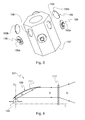
Figure 2 is a magnified view of a detail ofFigure 1 , showing the reflector; -
Figure 3 is a magnified view of a detail ofFigure 1 , showing the mounting of the light sources; -
Figure 4 is a simplified scheme showing the functioning of the lighting device ofFigure 1 ; -
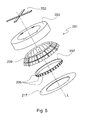
Figure 5 is an exploded perspective view of a first example of a lighting device employing point light sources; -
Figure 6 is a magnified view of a detail ofFigure 5 , showing the reflector; -
Figure 7 is a magnified view of a detail ofFigure 5 , showing the mounting of the light sources; -
Figure 8 is a plan view of a lighting device according to a first embodiment of the invention; -
Figure 9 is a perspective view of the mounting of the light sources of the lighting device ofFigure 8 ; -
Figure 10 is a cross section taken along a vertical plane of the mounting ofFigure 9 ; -
Figure 11 is a plan view of a lighting device according to a second embodiment of the invention; -
Figure 12 is a perspective view of the mounting of the light sources of the lighting device ofFigure 11 -
Figure 13 is a cross section taken along a vertical plane of the mounting ofFigure 12 . - With reference to
Figure 1 , a first example of alighting device 101 with point light sources and an optical system appositely dedicated thereto is shown. - Said
lighting device 101 comprises ahollow housing 103, containing: - a plurality of
point light sources 105 arranged on acentral mounting 107; in the illustrated example, said light sources are Light Emitting Diodes (LEDs) and there are six of them; - a
reflector 109, arranged around said mounting 107; - a refractor, namely a
lens 117. - In general, a vertical axis L can be identified in the
housing 103, which is cylindrical in the illustrated example but which could as well has a different shape, determined by both operational and aesthetic reasons. The housing 103 - and, as a consequence, the lighting device 101 - will be advantageously oriented so that the vertical axis L forms an angle close to 90° with the surface to be lighted. - According to the invention, the
light sources 105 are arranged along the external perimeter of themounting 107, preferably equally spaced from one another. Saidlight sources 105 are arranged on themounting 107 along a circumference lying on a plane that is substantially perpendicular to the longitudinal axis L and they are oriented so that the main emitting direction of each of said light sources is substantially perpendicular to the vertical axis L and, as a consequence, substantially parallel to the surface to be lighted. - As a result, the light beam emitted by the
light sources 105 is not directed towards the surface to be lighted; on the contrary, this light beam is directed towards thereflector 109 having the function of collecting, reflecting and directing the light flux emitted by thelight sources 105 towards the surface to be lighted. - As shown in
Figure 2 , thereflector 109 has aninner surface 109a comprising a plurality of concavelongitudinal channels 111, open towards thelight sources 105, preferably provided in the same number as thelight sources 105, each channel facing acorresponding source 105. - Thus, each
channel 111 is dedicated to thecorresponding light source 105, so as to reflect and direct the light flux thereof in an optimum way, as it will be disclosed in detail hereinafter. - Moreover, in order to optimise the performances of the
reflector 109, the surface of thelongitudinal channels 111 is deformed by means of corrugations or undulations so as to obtain a rough surface. More particularly, in the example ofFigures 1 - 3 , said surface is provided withtransversal corrugations 113. - The configuration of the
reflector 109 so obtained results in a lower light intensity with respect to a reflector with a smooth surface, but it allows to illuminate a larger area, so that the light coming from thelight sources 105 can be correctly directed onto the surface to be lighted. - As a general rule, the
inner surface 109a of thereflector 109 is uniformly subdivided intochannels 111. Nevertheless, the shape and size of thesechannels 111 can vary depending on the number of the expected light sources, as well as on technical or aesthetic needs - if any - concerning the overall size of thelighting device 101. Therefore, on thesurface 109a thechannels 111 can be in some cases alternated with flat, smoothintermediate portions 115. - It is evident that, since said
intermediate portions 115 do not provide a relevant contribution to the reflection of the light emitted by thelight sources 105, the optimisation of the geometry of thereflector 109 implies the minimization of the surface of saidintermediate portions 115. - The
reflector 109 is preferably made of a plastic material obtained by pressure die casting, such as polycarbonate, and theinner surface 109a is metallized by a process of aluminium vacuum deposition. Preferably, a thin silicon-based protection layer is provided for protecting the metallizedsurface 109a from weather. - Referring now to
Figure 3 , thelight sources 105 and the mounting 107 carrying said light sources are shown in detail. - As anticipated above, in the example illustrated in
Figure 1 - 3 LEDs 105 are employed as light sources, said LEDs being arranged along the external perimeter of the mounting 107, aligned and equally spaced from one another. - As well known,
LEDs 105 comprise asmall bulb 105a carried by asemiconductor chip 105b, wherein an anode and a cathode are obtained: by letting an electric current flow through thechip 105b, photons can be produced from the recombination of electron-hole pairs, leave the chip and be emitted as light. - In the example illustrated in
Figures 1 - 3 , there are six of said light sources; correspondingly, the mounting 107 has the shape of an hexagon-based prism, with aLED 105 mounted on each lateral face, in aproper seat 108. - Since the performances of the LEDs deteriorate with the increasing of temperature, it is desirable that the mounting 107, besides supporting the LEDs, also carries out the function of heat dissipator, so as to evacuate the heat generated by the LEDS during operation. To this purpose, the mounting 107 is made of a material having a high thermal conductivity, typically anodized aluminium.
- With reference to
Figure 4 , the optical functioning of thelighting device 101 is schematically shown. - As well known, LEDs emit a light beam in a cone C centred around a main emitting direction D and having an angle of about 120°.
- As disclosed above, each
LED 105 is oriented so that its main emitting direction D is substantially perpendicular to the vertical axis L of thelighting device 101; saidLED 105 is oriented towards the surface of thereflector 109 and, more particularly, towards thelongitudinal channel 111 of saidreflector 109 facing saidLED 105. - Advantageously, the dimensions of the
longitudinal channel 111 are set so as to intercept the most part of the light cone C emitted by theLED 105, reflect it and direct it in a beam F oriented along a direction that is substantially parallel to the vertical axis L of thelighting device 101. - At the outlet of said
lighting device 101, the beam F is intercepted by thelens 117, giving as final result the refracted light beam F'. - Referring now to
Figures 5 - 7 , a second example of alighting device 201 with point light sources and an optical system appositely dedicated thereto is illustrated. - As shown in
Figure 5 , saidlighting device 201 comprises ahollow housing 203, arranged for being mounted on supportingbrackets 202 and containing: - a plurality of point
light sources 205 arranged on a central mounting 207; in the illustrated example, said light sources are Light Emitting Diodes (LEDs) 205 and there are thirty of them; - a
reflector 209 arranged around said mounting 207; - a refractor, namely a
lens 217. - In the illustrated example, the
lens 217 has an annular shape. - Also in the example of
Figure 5 , thelight sources 205 are arranged along a circumference on the external perimeter of mounting 207, preferably equally spaced from one another and arranged so as to lie in a plane substantially perpendicular to the vertical axis L of thelighting device 201; saidlight sources 205 are oriented so that the main emitting direction of each light source is perpendicular to the vertical axis L and, as a consequence, substantially parallel to the surface to be lighted. - The light beam of the
light sources 205 is therefore directed towards thereflector 209. - As shown in
Figure 6 , thereflector 209 has aninner surface 209a comprising concavelongitudinal channels 211, open towards thelight sources 205, preferably provided in the same number as thelight sources 205, each channel facing acorresponding source 205. - Also in this case the surface of the
longitudinal channels 211 is provided with a plurality of deformations, namelytransversal corrugations 213, in order to optimise thereflector 209 performances. - Referring now to
Figure 7 , thelight sources 205 are shown in detail, as well as the mounting 207 wherein said light sources are arranged, inproper seats 208. - Due to the large number of light sources, in this second example the mounting 207 has a substantially cylindrical shape and - also in this embodiment - besides supporting the LEDs, it also carries out the function of heat dissipator, so as to evacuate the heat generated by the LEDs in operation.
- The optical functioning of the
lighting device 201 is substantially similar to the one described above with reference toFigure 4 . - Experimental tests carried out on lighting devices of the kind illustrated in
Figures 1 - 3 and inFigures 5 - 7 have proved that, for the same performances in terms of illumination, such lighting devices with point light sources and an optical system appositely dedicated thereto allow to obtain a reduction of the energy consumption with respect to conventional devices (sodium vapour lamps, high pressure mercury vapour lamps including metal iodides) over 70%. - Even though allowing a considerable reduction in energy consumption, the structure of the above-described lighting devices does not allow to optimize the removal of the heat generated by the light sources and, contextually, to minimize the overall size of the lighting device for the same performances in terms of illumination.
- In
Figure 8 , alighting device 301 according to a first embodiment of the invention is shown. - Said
lighting device 301 comprises ahollow housing 303 with circular plan, containing: - a plurality of point
light sources - a
reflector 309; - a refractor, namely a lens.
- As better shown in
Figures 9 and 10 , according to the invention the mounting 307 carrying theLEDs base 307d from which a pair ofarms transversal arms 307c, so that afree gap 308 is defined between saidarms - Said mounting 307 is made of a material having a high thermal conductivity, for instance anodized aluminium.
- It will be evident to the person skilled in the art that the mounting 307, thanks to its material and to its specific geometrical structure, providing for two
arms - The
base 307d of the mounting 307 it is then directly fixed (for instance by means of a paste having a high thermal conductivity) to thehousing 303, which in turn is made of a material having a high thermal conductivity, for instance aluminium. Thus, the heat generated by the LEDs is removed at first from the LEDs to the mounting and then, through said mounting, to thehousing 303 and to the outside environment. - Thanks to this effective removal of the heat, it will be possible to mount both a plurality of
LEDs 305a along the perimeter of the external surface of theexternal arm 307a of the mounting 307 and a plurality ofLEDs 305b along the perimeter of the internal surface of theinternal arm 307b of said mounting 307. Said LEDs will preferably be aligned and equally spaced from one another. More particularly, in the illustrated example, it is possible to provide twenty-four LEDs on theexternal arm 307a of the mounting 307 and twelve LEDs on theinternal arm 307b of the mounting 307, for a total of thirty-six LEDs. - Thanks to the specific geometrical structure of the mounting 307 it will be always possible to maintain the temperature of the
LEDs - Now, on the one hand it will be clear to the person skilled in the art that with a simple, conventional annular support it would be impossible to mount LEDs on both opposed walls of the mounting without causing a temperature increase and a consequent degradation of the performances of the LEDs themselves.
- On the other hand, it will also be clear that the possibility of providing LEDs on both the arms of the mounting 307 allows to obtain - for the same number of the employed LEDs - a lighting device having very limited size.
- In the illustrated embodiment, the
gap 308 defined between thearms LEDs external housing 303 and the outside environment is sufficient for maintaining the temperature of said LEDs below a pre-set threshold, of about 80°C. - However, in case of specific needs or of specific conditions of application (for instance in case of applications in environments at high temperature), in an alternative embodiment it is also possible to provide the circuit of a cooling fluid inside said
gap 308, so as to further optimize the removal of the heat generated by theLEDs - Referring again to
Figure 8 , as in the above-illustrated examples, theLEDs arms housing 303 and to the plane of the lens) and, as a consequence, substantially parallel to the surface to be lighted and directed towards thereflector 309. -
Said reflector 309 extends on both sides (internal and external) of the mounting 307 and has an inner surface comprising concavelongitudinal channels LEDs LEDs LED channel LED - Also in the embodiment illustrated in
Figure 8 , the surface of thelongitudinal channels - As a general rule, the inner surface of the reflector is uniformly subdivided into the channels; nevertheless, the shape and size of these channels can vary depending on the specific needs of the application and said channels can be in some cases alternated with flat, smooth intermediate portions.
- For instance, in the illustrated embodiment, the portion of the
reflector 309 on the internal side of the mounting 307 is completely subdivided into thechannels 311b, converging in a central cusp; on the contrary, in the portion of thereflector 309 on the external side of the mounting 307,smooth portions 315a alternated with thechannels 311a are present. - As in the above-illustrated examples, the
reflector 309 is preferably made of a plastic material obtained by pressure die casting, such as polycarbonate, and the inner surface thereof is metallized, for instance by a process of aluminium vacuum deposition, and preferably provided with a thin silicon-based protection layer. - From the above disclosure, it is clear that the optical functioning of the
lighting device 301 is substantially similar to the one described above with reference toFigure 4 . - Referring now to
Figure 11 , alighting device 401 according to a second embodiment of the invention is shown. - Said
lighting device 401 comprises ahollow housing 403 with rectangular plan, containing: - a plurality of point
light sources - a
reflector 409; - a refractor, namely a lens.
- As better shown in
Figures 12 and 13 , according to the invention the mounting 407 carrying theLEDs base 407d from which a pair ofarms transversal arms 407c, so that afree gap 408 is defined between saidarms - In this embodiment, the
base 407d of the mounting 407 is in turn "U"-shaped, so that afurther gap 410 is advantageously defined below thegap 408. - Said
base 407d is then directly fixed (for instance by means of a paste having a high thermal conductivity) to thehousing 403, which in turn is made of a material having a high thermal conductivity, for instance aluminium. Thus, the heat generated by the LEDs is removed at first from the LEDs to the mounting and then, through said mounting, to thehousing 403 and to the outside environment. - Also in this case, the mounting 407 allows to remove in an optimum way the heat generated by the light sources mounted thereon and it allows to mount a plurality of
LEDs arm - As a result, a high number of light sources - nine LEDs on each arm of the mounting 407, for a total of eighteen LEDs - can be mounted in a lighting device of limited size, while assuring an effective removal of the heat generated by the light sources themselves.
- Also in the case of a rectilinear geometrical structure as shown in
Figures 12 and 13 , the circuit of a cooling fluid can be provided inside saidgap 308 and/or saidgap 410, so as to further optimize the heat removal. - Referring again to
Figure 11 , also in this embodiment, theLEDs arms housing 403 and to the plane of the lens) and, as a consequence, substantially parallel to the surface to be lighted and directed towards thereflector 409. -
Said reflector 409 extends on both sides (right and left) of the mounting 407 and has an inner surface comprising concavelongitudinal channels intermediate portions LEDs LEDs LED channel LED longitudinal channels - The
reflector 409 is preferably made of a plastic material obtained by pressure die casting, such as polycarbonate, and the inner surface thereof is metallized, for instance by a process of aluminium vacuum deposition, and preferably provided with a thin silicon-based protection layer. - Concerning the optical functioning of the
lighting device 401, it will substantially follow the behaviour described above with reference toFigure 4 . - From the above description, it will be clear to the person skilled in the art that the intended objects are achieved by the invention, which allows to obtain a lighting device of limited size comprising a high number of point light sources without causing a temperature increase, so as to obtain satisfactory performances in terms of illumination and reliability.
- It will be also that the illustrated embodiments are given by way of a non-limiting example and many variants and modifications can be made, still remaining within the extent of the present invention, as defined by the appended claims.
Claims (15)
- Lighting device (301;401), comprising a hollow housing (303;403) containing:- a plurality of point light sources (305a,305b;405a,405b) arranged on a mounting (307;407) made of a material having a high thermal conductivity;- a reflector (309;409);- a refractor or a lens;said point light sources (305a,305b;405a,405b) being arranged in a plane that is substantially perpendicular to the vertical axis of said housing (303;403) and being oriented so that the main emitting direction of each light source is substantially perpendicular to said vertical axis and directed towards said reflector (309;409), the inner surface of said reflector (309;409) comprising a plurality of concave longitudinal channels (311a,311b;411a,411b) open towards said light sources (305a,305b;405a,405b) characterised in that said mounting (307;407) comprises a pair of arms (307a,307b;407a,407b) separated and spaced from each other, so that a gap (308,408) is defined between said arms, said point light sources (305a,305b;405a,405b) being arranged on both said arms (307a,307b;407a,407b).
- Lighting device (301;401) according to claim 1, wherein said point light sources (305a,305b;405a,405b) are arranged on each of said arms (307a,307b;407a,407b) on the wall opposed to the wall facing said gap (308;408).
- Lighting device (301;401) according to claim 2, wherein said point light sources (305a,305b;405a,405b) are aligned and preferably equally spaced from one another along said walls of said arms of said mounting (307;407).
- Lighting device (301;401) according to claim 1, wherein said mounting comprises a base (307d;407d) directly fixed to said housing (303;403), said arms (307a,307b;407a,407b) being connected to said base by means of transversal arms (307c;407c) and wherein said housing is made of a high thermal conductivity.
- Lighting device (301;401) according to claim 4, wherein said base (407d) of said mounting is "U"-shaped.
- Lighting device (301;401) according to any of the claims 1 to 5, wherein the circuit of a cooling fluid is arranged inside said gap (308;408) of said mounting (307;407).
- Lighting device (301;401) according to any of the claims 1 to 6, wherein said arms (307a,307b;407a,407b) of said mounting (307;407) are parallel to each other.
- Lighting device (301;401) according to any of the claims 1 to 7, wherein said mounting (307) has a substantially annular shape.
- Lighting device (301;401) according to any of the claims 1 to 7, wherein said mounting (407) has a substantially rectilinear shape.
- Lighting device (301;401) according to any of the claims 1 to 9, wherein said mounting (307;407) is made of anodized aluminium.
- Lighting device (301;401) according to claim 1, wherein said reflector (309;409) extends on both sides of said mounting (307;407) and wherein said concave longitudinal channels (311a,311b;411a,411b) are provided in the same number as said light sources, each of said channels facing a corresponding light source (305a,305b;405a,405b).
- Lighting device (301;401) according to claim 1, wherein the surface of said concave longitudinal channels (311a,311b;411a,411b) is deformed by means of corrugations or undulations so as to obtain a rough surface.
- Lighting device (301;401) according to claim 12, wherein said concave longitudinal channels (311a,311b;411a,411b) are provided with transversal corrugations (313a,313b;413a,413b).
- Lighting device (301;401) according to claim 1 or 8 or 9, wherein said reflector (309;409) is made of plastic material obtained by pressure die casting and wherein the inner surface of said reflector comprises a metallized surface layer.
- Lighting device (301;401) according to any of the preceding claims, wherein said point light sources are light emitting diodes (305a,305b;405a,405b).
Priority Applications (1)
| Application Number | Priority Date | Filing Date | Title |
|---|---|---|---|
| EP09159743A EP2116756B1 (en) | 2008-05-09 | 2009-05-08 | Lighting device |
Applications Claiming Priority (2)
| Application Number | Priority Date | Filing Date | Title |
|---|---|---|---|
| EP08425318 | 2008-05-09 | ||
| EP09159743A EP2116756B1 (en) | 2008-05-09 | 2009-05-08 | Lighting device |
Publications (2)
| Publication Number | Publication Date |
|---|---|
| EP2116756A1 true EP2116756A1 (en) | 2009-11-11 |
| EP2116756B1 EP2116756B1 (en) | 2011-12-28 |
Family
ID=39743867
Family Applications (1)
| Application Number | Title | Priority Date | Filing Date |
|---|---|---|---|
| EP09159743A Not-in-force EP2116756B1 (en) | 2008-05-09 | 2009-05-08 | Lighting device |
Country Status (2)
| Country | Link |
|---|---|
| EP (1) | EP2116756B1 (en) |
| AT (1) | ATE539296T1 (en) |
Cited By (3)
| Publication number | Priority date | Publication date | Assignee | Title |
|---|---|---|---|---|
| EP2442021A1 (en) * | 2010-09-08 | 2012-04-18 | Ceramate Technical Co., Ltd | LED disc lamp |
| EP3098505A1 (en) * | 2015-05-28 | 2016-11-30 | Zodiac Aero Electric | Aircraft lighting device and central integration of its additional function |
| EP3244128A1 (en) * | 2016-05-11 | 2017-11-15 | Zumtobel Lighting GmbH | Luminaire |
Citations (11)
| Publication number | Priority date | Publication date | Assignee | Title |
|---|---|---|---|---|
| WO2001086198A1 (en) * | 2000-05-08 | 2001-11-15 | Farlight Llc | Luminaire having optical transformer providing precalculated angular intensity distribution |
| US20040125610A1 (en) * | 2002-06-27 | 2004-07-01 | North American Lighting, Inc. | Apparatus and method for providing a modular vehicle light device |
| EP1471304A2 (en) * | 2003-04-25 | 2004-10-27 | Stanley Electric Co., Ltd. | Vehicle lamp |
| WO2005055328A1 (en) | 2003-12-05 | 2005-06-16 | Mitsubishi Denki Kabushiki Kaisha | Light emitting device and illumination instrument using the same |
| JP2005327577A (en) | 2004-05-13 | 2005-11-24 | Momo Alliance Co Ltd | Light emitting device and street light, signal light and indicator light using the light emitting device |
| US20060181873A1 (en) | 2005-02-17 | 2006-08-17 | Underwater Kinetics, Inc. | Lighting system and method and reflector for use in same |
| EP1698823A2 (en) * | 2005-03-03 | 2006-09-06 | Dialight Corporation | Beacon light with reflector and light emitting diodes |
| US20070090737A1 (en) * | 2005-10-20 | 2007-04-26 | Foxconn Technology Co., Ltd. | Light-emitting diode assembly and method of fabrication |
| EP1826474A1 (en) | 2006-02-22 | 2007-08-29 | Optics Lite S.r.L. | Optical projector with radial LED light source |
| CN200946775Y (en) | 2006-08-18 | 2007-09-12 | 支忠 | Large power LED road lighting lamp |
| CN101059213A (en) | 2007-05-23 | 2007-10-24 | 宁波燎原工业股份有限公司 | LED road lamp head |
-
2009
- 2009-05-08 AT AT09159743T patent/ATE539296T1/en active
- 2009-05-08 EP EP09159743A patent/EP2116756B1/en not_active Not-in-force
Patent Citations (11)
| Publication number | Priority date | Publication date | Assignee | Title |
|---|---|---|---|---|
| WO2001086198A1 (en) * | 2000-05-08 | 2001-11-15 | Farlight Llc | Luminaire having optical transformer providing precalculated angular intensity distribution |
| US20040125610A1 (en) * | 2002-06-27 | 2004-07-01 | North American Lighting, Inc. | Apparatus and method for providing a modular vehicle light device |
| EP1471304A2 (en) * | 2003-04-25 | 2004-10-27 | Stanley Electric Co., Ltd. | Vehicle lamp |
| WO2005055328A1 (en) | 2003-12-05 | 2005-06-16 | Mitsubishi Denki Kabushiki Kaisha | Light emitting device and illumination instrument using the same |
| JP2005327577A (en) | 2004-05-13 | 2005-11-24 | Momo Alliance Co Ltd | Light emitting device and street light, signal light and indicator light using the light emitting device |
| US20060181873A1 (en) | 2005-02-17 | 2006-08-17 | Underwater Kinetics, Inc. | Lighting system and method and reflector for use in same |
| EP1698823A2 (en) * | 2005-03-03 | 2006-09-06 | Dialight Corporation | Beacon light with reflector and light emitting diodes |
| US20070090737A1 (en) * | 2005-10-20 | 2007-04-26 | Foxconn Technology Co., Ltd. | Light-emitting diode assembly and method of fabrication |
| EP1826474A1 (en) | 2006-02-22 | 2007-08-29 | Optics Lite S.r.L. | Optical projector with radial LED light source |
| CN200946775Y (en) | 2006-08-18 | 2007-09-12 | 支忠 | Large power LED road lighting lamp |
| CN101059213A (en) | 2007-05-23 | 2007-10-24 | 宁波燎原工业股份有限公司 | LED road lamp head |
Cited By (9)
| Publication number | Priority date | Publication date | Assignee | Title |
|---|---|---|---|---|
| EP2442021A1 (en) * | 2010-09-08 | 2012-04-18 | Ceramate Technical Co., Ltd | LED disc lamp |
| EP3098505A1 (en) * | 2015-05-28 | 2016-11-30 | Zodiac Aero Electric | Aircraft lighting device and central integration of its additional function |
| US20160347474A1 (en) * | 2015-05-28 | 2016-12-01 | Zodiac Aero Electric | Lighting device for aircraft allowing the integration of additional functions at its center |
| FR3036687A1 (en) * | 2015-05-28 | 2016-12-02 | Zodiac Aero Electric | LIGHTING DEVICE FOR AN AIRCRAFT FOR THE INTEGRATION OF ADDITIONAL FUNCTIONS IN ITS CENTER |
| CN106195919A (en) * | 2015-05-28 | 2016-12-07 | Zodiac航空电器 | Allow the airborne vehicle luminaire of the integrated additional function of the heart wherein |
| US10246199B2 (en) | 2015-05-28 | 2019-04-02 | Zodiac Aero Electric | Lighting device for aircraft allowing the integration of additional functions at its center |
| RU2721431C2 (en) * | 2015-05-28 | 2020-05-19 | Зодиак Аэро Электрик | Aircraft lighting device configured to embed additional functions in its center |
| EP3244128A1 (en) * | 2016-05-11 | 2017-11-15 | Zumtobel Lighting GmbH | Luminaire |
| AT16635U1 (en) * | 2016-05-11 | 2020-03-15 | Zumtobel Lighting Gmbh | lamp |
Also Published As
| Publication number | Publication date |
|---|---|
| ATE539296T1 (en) | 2012-01-15 |
| EP2116756B1 (en) | 2011-12-28 |
Similar Documents
| Publication | Publication Date | Title |
|---|---|---|
| JP5331571B2 (en) | LED reflection lamp | |
| US8721114B2 (en) | LED lamp apparatus and method of making an LED lamp apparatus | |
| CA2716832C (en) | Heat removal system and method for light emitting diode lighting apparatus | |
| KR101227525B1 (en) | Lighting apparatus | |
| KR101377965B1 (en) | Lighting apparatus | |
| EP4105549A1 (en) | Ceiling lamp | |
| KR101201490B1 (en) | Eco-friendly louver type LED luminaire with DSSCDye-sensitized solar cell | |
| US8696156B2 (en) | LED light bulb with light scattering optics structure | |
| US10788177B2 (en) | Lighting fixture with reflector and template PCB | |
| CN102192463A (en) | Illumination device | |
| JP2011100714A (en) | Led lighting unit | |
| US10132487B2 (en) | Luminaire heat sink | |
| CN104676315A (en) | Internal reflection lamp | |
| EP2116756B1 (en) | Lighting device | |
| KR101132217B1 (en) | Light-emitting diode illumination device of asymmetry reflective | |
| WO2010094041A2 (en) | Systems for retrofitting an existing light fixture with an led luminaire | |
| KR101240908B1 (en) | LED illuminator | |
| KR20110023231A (en) | Stick LED Lighting Fixtures | |
| US9857043B2 (en) | LED H4 retrofit lamp unit | |
| TW201113467A (en) | Reduced size LED luminaire | |
| WO2010045763A1 (en) | Light collimating device | |
| CN105351856A (en) | LED (light-emitting diode) locomotive headlamp | |
| CA2509302C (en) | Industrial up light reflector | |
| JP2000260202A (en) | Aviation obstacle lights | |
| KR20120133056A (en) | Optical semiconductor based lighting apparatus |
Legal Events
| Date | Code | Title | Description |
|---|---|---|---|
| PUAI | Public reference made under article 153(3) epc to a published international application that has entered the european phase |
Free format text: ORIGINAL CODE: 0009012 |
|
| AK | Designated contracting states |
Kind code of ref document: A1 Designated state(s): AT BE BG CH CY CZ DE DK EE ES FI FR GB GR HR HU IE IS IT LI LT LU LV MC MK MT NL NO PL PT RO SE SI SK TR |
|
| 17P | Request for examination filed |
Effective date: 20100511 |
|
| 17Q | First examination report despatched |
Effective date: 20100621 |
|
| RAP1 | Party data changed (applicant data changed or rights of an application transferred) |
Owner name: PWP ILLUMINA S.R.L. |
|
| REG | Reference to a national code |
Ref country code: DE Ref legal event code: R079 Ref document number: 602009004321 Country of ref document: DE Free format text: PREVIOUS MAIN CLASS: F21K0007000000 Ipc: F21K0099000000 |
|
| RIC1 | Information provided on ipc code assigned before grant |
Ipc: F21K 99/00 20100101AFI20110516BHEP |
|
| GRAP | Despatch of communication of intention to grant a patent |
Free format text: ORIGINAL CODE: EPIDOSNIGR1 |
|
| GRAS | Grant fee paid |
Free format text: ORIGINAL CODE: EPIDOSNIGR3 |
|
| GRAA | (expected) grant |
Free format text: ORIGINAL CODE: 0009210 |
|
| AK | Designated contracting states |
Kind code of ref document: B1 Designated state(s): AT BE BG CH CY CZ DE DK EE ES FI FR GB GR HR HU IE IS IT LI LT LU LV MC MK MT NL NO PL PT RO SE SI SK TR |
|
| REG | Reference to a national code |
Ref country code: GB Ref legal event code: FG4D |
|
| REG | Reference to a national code |
Ref country code: CH Ref legal event code: EP |
|
| REG | Reference to a national code |
Ref country code: AT Ref legal event code: REF Ref document number: 539296 Country of ref document: AT Kind code of ref document: T Effective date: 20120115 |
|
| REG | Reference to a national code |
Ref country code: IE Ref legal event code: FG4D |
|
| REG | Reference to a national code |
Ref country code: DE Ref legal event code: R096 Ref document number: 602009004321 Country of ref document: DE Effective date: 20120301 |
|
| REG | Reference to a national code |
Ref country code: NL Ref legal event code: VDEP Effective date: 20111228 |
|
| PG25 | Lapsed in a contracting state [announced via postgrant information from national office to epo] |
Ref country code: LT Free format text: LAPSE BECAUSE OF FAILURE TO SUBMIT A TRANSLATION OF THE DESCRIPTION OR TO PAY THE FEE WITHIN THE PRESCRIBED TIME-LIMIT Effective date: 20111228 Ref country code: NO Free format text: LAPSE BECAUSE OF FAILURE TO SUBMIT A TRANSLATION OF THE DESCRIPTION OR TO PAY THE FEE WITHIN THE PRESCRIBED TIME-LIMIT Effective date: 20120328 |
|
| LTIE | Lt: invalidation of european patent or patent extension |
Effective date: 20111228 |
|
| PG25 | Lapsed in a contracting state [announced via postgrant information from national office to epo] |
Ref country code: GR Free format text: LAPSE BECAUSE OF FAILURE TO SUBMIT A TRANSLATION OF THE DESCRIPTION OR TO PAY THE FEE WITHIN THE PRESCRIBED TIME-LIMIT Effective date: 20120329 Ref country code: LV Free format text: LAPSE BECAUSE OF FAILURE TO SUBMIT A TRANSLATION OF THE DESCRIPTION OR TO PAY THE FEE WITHIN THE PRESCRIBED TIME-LIMIT Effective date: 20111228 Ref country code: SI Free format text: LAPSE BECAUSE OF FAILURE TO SUBMIT A TRANSLATION OF THE DESCRIPTION OR TO PAY THE FEE WITHIN THE PRESCRIBED TIME-LIMIT Effective date: 20111228 Ref country code: SE Free format text: LAPSE BECAUSE OF FAILURE TO SUBMIT A TRANSLATION OF THE DESCRIPTION OR TO PAY THE FEE WITHIN THE PRESCRIBED TIME-LIMIT Effective date: 20111228 Ref country code: HR Free format text: LAPSE BECAUSE OF FAILURE TO SUBMIT A TRANSLATION OF THE DESCRIPTION OR TO PAY THE FEE WITHIN THE PRESCRIBED TIME-LIMIT Effective date: 20111228 |
|
| PG25 | Lapsed in a contracting state [announced via postgrant information from national office to epo] |
Ref country code: CY Free format text: LAPSE BECAUSE OF FAILURE TO SUBMIT A TRANSLATION OF THE DESCRIPTION OR TO PAY THE FEE WITHIN THE PRESCRIBED TIME-LIMIT Effective date: 20111228 Ref country code: BE Free format text: LAPSE BECAUSE OF FAILURE TO SUBMIT A TRANSLATION OF THE DESCRIPTION OR TO PAY THE FEE WITHIN THE PRESCRIBED TIME-LIMIT Effective date: 20111228 |
|
| PG25 | Lapsed in a contracting state [announced via postgrant information from national office to epo] |
Ref country code: CZ Free format text: LAPSE BECAUSE OF FAILURE TO SUBMIT A TRANSLATION OF THE DESCRIPTION OR TO PAY THE FEE WITHIN THE PRESCRIBED TIME-LIMIT Effective date: 20111228 Ref country code: BG Free format text: LAPSE BECAUSE OF FAILURE TO SUBMIT A TRANSLATION OF THE DESCRIPTION OR TO PAY THE FEE WITHIN THE PRESCRIBED TIME-LIMIT Effective date: 20120328 Ref country code: SK Free format text: LAPSE BECAUSE OF FAILURE TO SUBMIT A TRANSLATION OF THE DESCRIPTION OR TO PAY THE FEE WITHIN THE PRESCRIBED TIME-LIMIT Effective date: 20111228 Ref country code: IS Free format text: LAPSE BECAUSE OF FAILURE TO SUBMIT A TRANSLATION OF THE DESCRIPTION OR TO PAY THE FEE WITHIN THE PRESCRIBED TIME-LIMIT Effective date: 20120428 Ref country code: EE Free format text: LAPSE BECAUSE OF FAILURE TO SUBMIT A TRANSLATION OF THE DESCRIPTION OR TO PAY THE FEE WITHIN THE PRESCRIBED TIME-LIMIT Effective date: 20111228 Ref country code: NL Free format text: LAPSE BECAUSE OF FAILURE TO SUBMIT A TRANSLATION OF THE DESCRIPTION OR TO PAY THE FEE WITHIN THE PRESCRIBED TIME-LIMIT Effective date: 20111228 |
|
| PG25 | Lapsed in a contracting state [announced via postgrant information from national office to epo] |
Ref country code: RO Free format text: LAPSE BECAUSE OF FAILURE TO SUBMIT A TRANSLATION OF THE DESCRIPTION OR TO PAY THE FEE WITHIN THE PRESCRIBED TIME-LIMIT Effective date: 20111228 Ref country code: PT Free format text: LAPSE BECAUSE OF FAILURE TO SUBMIT A TRANSLATION OF THE DESCRIPTION OR TO PAY THE FEE WITHIN THE PRESCRIBED TIME-LIMIT Effective date: 20120430 Ref country code: PL Free format text: LAPSE BECAUSE OF FAILURE TO SUBMIT A TRANSLATION OF THE DESCRIPTION OR TO PAY THE FEE WITHIN THE PRESCRIBED TIME-LIMIT Effective date: 20111228 |
|
| REG | Reference to a national code |
Ref country code: AT Ref legal event code: MK05 Ref document number: 539296 Country of ref document: AT Kind code of ref document: T Effective date: 20111228 |
|
| PG25 | Lapsed in a contracting state [announced via postgrant information from national office to epo] |
Ref country code: DK Free format text: LAPSE BECAUSE OF FAILURE TO SUBMIT A TRANSLATION OF THE DESCRIPTION OR TO PAY THE FEE WITHIN THE PRESCRIBED TIME-LIMIT Effective date: 20111228 |
|
| PLBE | No opposition filed within time limit |
Free format text: ORIGINAL CODE: 0009261 |
|
| STAA | Information on the status of an ep patent application or granted ep patent |
Free format text: STATUS: NO OPPOSITION FILED WITHIN TIME LIMIT |
|
| 26N | No opposition filed |
Effective date: 20121001 |
|
| PG25 | Lapsed in a contracting state [announced via postgrant information from national office to epo] |
Ref country code: MC Free format text: LAPSE BECAUSE OF NON-PAYMENT OF DUE FEES Effective date: 20120531 |
|
| REG | Reference to a national code |
Ref country code: DE Ref legal event code: R097 Ref document number: 602009004321 Country of ref document: DE Effective date: 20121001 |
|
| PG25 | Lapsed in a contracting state [announced via postgrant information from national office to epo] |
Ref country code: AT Free format text: LAPSE BECAUSE OF FAILURE TO SUBMIT A TRANSLATION OF THE DESCRIPTION OR TO PAY THE FEE WITHIN THE PRESCRIBED TIME-LIMIT Effective date: 20111228 |
|
| REG | Reference to a national code |
Ref country code: IE Ref legal event code: MM4A |
|
| PG25 | Lapsed in a contracting state [announced via postgrant information from national office to epo] |
Ref country code: MK Free format text: LAPSE BECAUSE OF FAILURE TO SUBMIT A TRANSLATION OF THE DESCRIPTION OR TO PAY THE FEE WITHIN THE PRESCRIBED TIME-LIMIT Effective date: 20111228 |
|
| PG25 | Lapsed in a contracting state [announced via postgrant information from national office to epo] |
Ref country code: IE Free format text: LAPSE BECAUSE OF NON-PAYMENT OF DUE FEES Effective date: 20120508 Ref country code: ES Free format text: LAPSE BECAUSE OF FAILURE TO SUBMIT A TRANSLATION OF THE DESCRIPTION OR TO PAY THE FEE WITHIN THE PRESCRIBED TIME-LIMIT Effective date: 20120408 |
|
| PG25 | Lapsed in a contracting state [announced via postgrant information from national office to epo] |
Ref country code: FI Free format text: LAPSE BECAUSE OF FAILURE TO SUBMIT A TRANSLATION OF THE DESCRIPTION OR TO PAY THE FEE WITHIN THE PRESCRIBED TIME-LIMIT Effective date: 20111228 |
|
| PG25 | Lapsed in a contracting state [announced via postgrant information from national office to epo] |
Ref country code: MT Free format text: LAPSE BECAUSE OF FAILURE TO SUBMIT A TRANSLATION OF THE DESCRIPTION OR TO PAY THE FEE WITHIN THE PRESCRIBED TIME-LIMIT Effective date: 20111228 |
|
| PGFP | Annual fee paid to national office [announced via postgrant information from national office to epo] |
Ref country code: DE Payment date: 20130603 Year of fee payment: 5 Ref country code: GB Payment date: 20130531 Year of fee payment: 5 |
|
| PGFP | Annual fee paid to national office [announced via postgrant information from national office to epo] |
Ref country code: IT Payment date: 20130530 Year of fee payment: 5 Ref country code: FR Payment date: 20130621 Year of fee payment: 5 |
|
| REG | Reference to a national code |
Ref country code: CH Ref legal event code: PL |
|
| PG25 | Lapsed in a contracting state [announced via postgrant information from national office to epo] |
Ref country code: LI Free format text: LAPSE BECAUSE OF NON-PAYMENT OF DUE FEES Effective date: 20130531 Ref country code: CH Free format text: LAPSE BECAUSE OF NON-PAYMENT OF DUE FEES Effective date: 20130531 |
|
| PG25 | Lapsed in a contracting state [announced via postgrant information from national office to epo] |
Ref country code: TR Free format text: LAPSE BECAUSE OF FAILURE TO SUBMIT A TRANSLATION OF THE DESCRIPTION OR TO PAY THE FEE WITHIN THE PRESCRIBED TIME-LIMIT Effective date: 20111228 |
|
| PG25 | Lapsed in a contracting state [announced via postgrant information from national office to epo] |
Ref country code: LU Free format text: LAPSE BECAUSE OF NON-PAYMENT OF DUE FEES Effective date: 20120508 |
|
| PG25 | Lapsed in a contracting state [announced via postgrant information from national office to epo] |
Ref country code: HU Free format text: LAPSE BECAUSE OF FAILURE TO SUBMIT A TRANSLATION OF THE DESCRIPTION OR TO PAY THE FEE WITHIN THE PRESCRIBED TIME-LIMIT Effective date: 20090508 |
|
| REG | Reference to a national code |
Ref country code: DE Ref legal event code: R119 Ref document number: 602009004321 Country of ref document: DE |
|
| GBPC | Gb: european patent ceased through non-payment of renewal fee |
Effective date: 20140508 |
|
| REG | Reference to a national code |
Ref country code: DE Ref legal event code: R119 Ref document number: 602009004321 Country of ref document: DE Effective date: 20141202 |
|
| REG | Reference to a national code |
Ref country code: FR Ref legal event code: ST Effective date: 20150130 |
|
| PG25 | Lapsed in a contracting state [announced via postgrant information from national office to epo] |
Ref country code: DE Free format text: LAPSE BECAUSE OF NON-PAYMENT OF DUE FEES Effective date: 20141202 Ref country code: IT Free format text: LAPSE BECAUSE OF NON-PAYMENT OF DUE FEES Effective date: 20140508 |
|
| PG25 | Lapsed in a contracting state [announced via postgrant information from national office to epo] |
Ref country code: GB Free format text: LAPSE BECAUSE OF NON-PAYMENT OF DUE FEES Effective date: 20140508 Ref country code: FR Free format text: LAPSE BECAUSE OF NON-PAYMENT OF DUE FEES Effective date: 20140602 |