EP2118455B1 - Dispositif combiné de verrouillage et de limitation d'angle de rotation d'un variateur d'arbre à cames - Google Patents
Dispositif combiné de verrouillage et de limitation d'angle de rotation d'un variateur d'arbre à cames Download PDFInfo
- Publication number
- EP2118455B1 EP2118455B1 EP07857921A EP07857921A EP2118455B1 EP 2118455 B1 EP2118455 B1 EP 2118455B1 EP 07857921 A EP07857921 A EP 07857921A EP 07857921 A EP07857921 A EP 07857921A EP 2118455 B1 EP2118455 B1 EP 2118455B1
- Authority
- EP
- European Patent Office
- Prior art keywords
- angle limiting
- rotational angle
- bar
- rotational
- slot
- Prior art date
- Legal status (The legal status is an assumption and is not a legal conclusion. Google has not performed a legal analysis and makes no representation as to the accuracy of the status listed.)
- Not-in-force
Links
Images


Classifications
-
- F—MECHANICAL ENGINEERING; LIGHTING; HEATING; WEAPONS; BLASTING
- F01—MACHINES OR ENGINES IN GENERAL; ENGINE PLANTS IN GENERAL; STEAM ENGINES
- F01L—CYCLICALLY OPERATING VALVES FOR MACHINES OR ENGINES
- F01L1/00—Valve-gear or valve arrangements, e.g. lift-valve gear
- F01L1/34—Valve-gear or valve arrangements, e.g. lift-valve gear characterised by the provision of means for changing the timing of the valves without changing the duration of opening and without affecting the magnitude of the valve lift
- F01L1/344—Valve-gear or valve arrangements, e.g. lift-valve gear characterised by the provision of means for changing the timing of the valves without changing the duration of opening and without affecting the magnitude of the valve lift changing the angular relationship between crankshaft and camshaft, e.g. using helicoidal gear
- F01L1/3442—Valve-gear or valve arrangements, e.g. lift-valve gear characterised by the provision of means for changing the timing of the valves without changing the duration of opening and without affecting the magnitude of the valve lift changing the angular relationship between crankshaft and camshaft, e.g. using helicoidal gear using hydraulic chambers with variable volume to transmit the rotating force
- F01L2001/3445—Details relating to the hydraulic means for changing the angular relationship
- F01L2001/34453—Locking means between driving and driven members
- F01L2001/34459—Locking in multiple positions
-
- F—MECHANICAL ENGINEERING; LIGHTING; HEATING; WEAPONS; BLASTING
- F01—MACHINES OR ENGINES IN GENERAL; ENGINE PLANTS IN GENERAL; STEAM ENGINES
- F01L—CYCLICALLY OPERATING VALVES FOR MACHINES OR ENGINES
- F01L1/00—Valve-gear or valve arrangements, e.g. lift-valve gear
- F01L1/34—Valve-gear or valve arrangements, e.g. lift-valve gear characterised by the provision of means for changing the timing of the valves without changing the duration of opening and without affecting the magnitude of the valve lift
- F01L1/344—Valve-gear or valve arrangements, e.g. lift-valve gear characterised by the provision of means for changing the timing of the valves without changing the duration of opening and without affecting the magnitude of the valve lift changing the angular relationship between crankshaft and camshaft, e.g. using helicoidal gear
- F01L1/3442—Valve-gear or valve arrangements, e.g. lift-valve gear characterised by the provision of means for changing the timing of the valves without changing the duration of opening and without affecting the magnitude of the valve lift changing the angular relationship between crankshaft and camshaft, e.g. using helicoidal gear using hydraulic chambers with variable volume to transmit the rotating force
- F01L2001/3445—Details relating to the hydraulic means for changing the angular relationship
- F01L2001/34453—Locking means between driving and driven members
- F01L2001/34469—Lock movement parallel to camshaft axis
-
- F—MECHANICAL ENGINEERING; LIGHTING; HEATING; WEAPONS; BLASTING
- F01—MACHINES OR ENGINES IN GENERAL; ENGINE PLANTS IN GENERAL; STEAM ENGINES
- F01L—CYCLICALLY OPERATING VALVES FOR MACHINES OR ENGINES
- F01L1/00—Valve-gear or valve arrangements, e.g. lift-valve gear
- F01L1/34—Valve-gear or valve arrangements, e.g. lift-valve gear characterised by the provision of means for changing the timing of the valves without changing the duration of opening and without affecting the magnitude of the valve lift
- F01L1/344—Valve-gear or valve arrangements, e.g. lift-valve gear characterised by the provision of means for changing the timing of the valves without changing the duration of opening and without affecting the magnitude of the valve lift changing the angular relationship between crankshaft and camshaft, e.g. using helicoidal gear
- F01L1/3442—Valve-gear or valve arrangements, e.g. lift-valve gear characterised by the provision of means for changing the timing of the valves without changing the duration of opening and without affecting the magnitude of the valve lift changing the angular relationship between crankshaft and camshaft, e.g. using helicoidal gear using hydraulic chambers with variable volume to transmit the rotating force
- F01L2001/3445—Details relating to the hydraulic means for changing the angular relationship
- F01L2001/34483—Phaser return springs
Definitions
- the invention is in the technical field of internal combustion engines and relates to a combined locking and Drehwinkelbegrenzungs adopted a camshaft adjuster for an internal combustion engine.
- gas exchange valves are actuated by the cams of a camshaft rotated by the crankshaft.
- the cams roll on cam followers, such as drag levers, rocker arms or bucket tappets, which counteract the spring force of a valve spring holding the gas exchange valve in a closed position.
- cam followers such as drag levers, rocker arms or bucket tappets, which counteract the spring force of a valve spring holding the gas exchange valve in a closed position.
- the timing of the gas exchange valves can be specifically defined.
- the control times of the gas exchange valves are influenced as a function of the current operating state, such as speed or load.
- this can positively influence the exhaust gas behavior and reduce fuel consumption.
- the efficiency of the internal combustion engine the maximum torque and the maximum power can be increased.
- the opening and closing times of the gas exchange valves within a working cycle of the internal combustion engine by the relative rotational position (phase) between Cam and crankshaft specified. An adjustment of the timing of the gas exchange valves within the working cycle can thus be achieved by a relative change in the rotational position between the camshaft and crankshaft.
- camshaft adjuster For changing and fixing the relative rotational position between the cam and crankshaft, hereinafter referred to as "camshaft adjuster". Via camshaft adjuster, torque can be transmitted from the crankshaft to the camshaft. In addition, can be held by camshaft adjuster during operation of the internal combustion engine, the relative rotational position between the cam and crankshaft and adjusted within a certain angular range, so as to change the timing of the gas exchange valves.
- camshaft adjuster can be held by camshaft adjuster during operation of the internal combustion engine, the relative rotational position between the cam and crankshaft and adjusted within a certain angular range, so as to change the timing of the gas exchange valves.
- a camshaft adjuster usually comprises a driving part rotatably connected via a drive wheel to the crankshaft and a camshaft-fixed driven part, and an actuator connected between driving and driven part which transmits the torque from the drive part to the driven part and fixes and adjusts the relative rotational position between the and stripping section allows.
- the actuator can be operated electrically, hydraulically or pneumatically.
- Nockenweckenwellenversteller are typically designed as Axialkolbenversteller or Rotationskolbenversteller, which are explained in more detail below.
- the drive part is toothed via a helical toothing with a piston, which in turn is toothed via a helical toothing with the output part.
- a pressure chamber is formed, which is divided by the piston into two pressure chambers. If one of the two pressure chambers is acted upon by pressure medium, while the other is connected to a pressure medium outlet, the piston is in axial Direction shifted so that a change in the relative rotational position between the input and output part is caused by the helical gears.
- the drive part formed, for example, in the form of an outer rotor, and the driven part designed, for example, in the form of an inner rotor, are arranged concentrically to each other so as to be adjustable in rotation.
- the outer rotor may be composed of a plurality of rotatably interconnected components, such as housing with drive wheel and on the inner rotor (hereinafter referred to as rotor) rotatably mounted stator.
- a rotary piston adjuster pressure chambers are formed in the radial gap between the stator and the rotor, for example by a plurality of circumferentially spaced cavities are formed in the stator, which extend radially outwardly from the rotor and are pressure-tight in the axial direction by side walls.
- each of these pressure chambers extends radially outwardly connected to the rotor sealing element, hereinafter referred to as wings, whereby each pressure chamber is divided into two substantially pressure-tight pressure chambers. Through the wing, a flow of pressure medium from one pressure chamber into the other pressure chamber is at least largely prevented.
- pressure medium lines open to supply and / or discharge of pressure medium to and from the pressure chambers.
- the wings can be pivoted within the pressure chambers, so that via the rotatably connected to the camshaft rotor rotation of the camshaft and consequently a change in the relative rotational position between Camshaft and crankshaft is effected.
- the rotational position can be maintained by a corresponding equal pressurization of the two pressure chambers of a respective pressure chamber.
- a control of the hydraulic camshaft adjuster is effected by a control unit which controls the inflow and outflow of pressure medium to and from the individual pressure chambers on the basis of detected characteristics of the internal combustion engine, such as speed and load.
- the pressure medium flows are regulated for example by a control valve.
- a locking device for non-rotatable locking of the stator and rotor in a so-called base position is provided in which stator and rotor a desired rotational position, in particular an optimal rotational position for the start or idle of an internal combustion engine, take.
- a conventional locking device for locking rotor and stator in base position comprises, for example, a piston received in a recess of the rotor, which is urged by a spring in the axial direction of the inner rotor and can engage for locking in the base position in a gate formed by the gate, whereby a positive mechanical connection between rotor and stator is created.
- the base position is usually one of the maximum relative rotational positions (final rotational positions) from rotor to stator, referred to as the "early" or "late” position of the rotor.
- the retarded position corresponds to an end rotational position of the rotor in a twisting direction, which is directed counter to the (on the drive by the crankshaft) rotor rotational direction, while the early position of a final rotational position of the rotor in a twisting direction, which is the same direction to the rotor rotational direction, equivalent.
- the maximum possible rotation angle range is predetermined by the early or late stop of the wings within the pressure chambers or by a separate rotation angle limiting device, as is the case with camshaft adjusters made of sheet metal parts.
- a disadvantage of conventional camshaft adjusters is the fact that their assembly is therefore already relatively time consuming and costly, since the adjustment of the locking device of the desired base position corresponding rotary position of the rotor is to be considered, which in turn already with tolerances, for example by a rotational angle limiting device, afflicted is, so that the locking device can be adjusted in industrial mass production only with a relatively large locking clearance. As a result, this leads to a poorly defined rotational position of the rotor in base position and consequently to poorly set timing of the gas exchange valves.
- the object of the present invention is to provide a locking device of a camshaft adjuster for an internal combustion engine, by which the above-mentioned disadvantage of a relatively large locking play can be avoided.
- the locking device should be produced in a simple and cost-effective manner.
- a combined locking and rotational angle limiting device for non-rotatable locking and limiting the relative rotational adjustability of a crankshaft fixed or can be brought into drive connection with a crankshaft drive part and a rotatably adjustable thereto, camshaft fixed or can be brought into a drive connection with a camshaft output part of a camshaft adjuster for an internal combustion engine.
- the camshaft adjuster serves as a device for transmitting a torque between the input and output part as well as for adjusting and fixing the relative rotational position (phase position) between the crankshaft and the camshaft.
- Drive and driven part may be formed, for example in the form of an outer rotor with a drive wheel formed thereon, which is in drive connection with the crankshaft, and an inner rotor concentrically arranged to the outer rotor.
- the combined locking and rotational angle limiting device comprises a locking element accommodated in the driving or driven part, hereinafter referred to as "bolt”, which is displaceable by a displacement mechanism.
- bolt a locking element accommodated in the driving or driven part
- a bolt gate is formed in the corresponding other part, by which the bolt is positively received in the circumferential direction, so as to connect input and output member rotation with each other.
- the combined locking and rotational angle limiting device comprises a correspondingly different part shaped Drehwinkelbegrenzungskulisse, through which the same bar in the circumferential direction is receivable with distance from the boundary wall.
- substantially radial boundary wall sections of the boundary wall of the rotation angle limiting link serve as stops for recorded in the Drehwinkelbegrenzungskulisse latch at a relative rotational adjustment of drive and driven part in the two directions of rotation for adjusting a maximum rotational adjustability of drive and driven part.
- the bolt gate, the rotation angle limiting link and the bolt are arranged so that the bolt by the displacement mechanism in a locking position, in which he engages in the bolt gate and is guided by the bolt gate, and in an unlocking position, in he is released from the bar gate, only engages the Drehwinkelbegrenzungskulisse and can be guided by the Drehwinkelbegrenzungskulisse, is displaced.
- the locking linkage is arranged within an (imaginary) extension in the direction of displacement of the bolt of the (limiting wall of) the rotational angle limiting link.
- the inventive combined locking and rotational angle limiting device thus locking of drive and driven part can be achieved with a compared to conventional locking devices very low locking clearance, since only an adjustment of the same bolt within the bolt gate and the rotational angle limiting link is required.
- it is not necessary to take into account any tolerances concerning the separate rotation angle limiting device.
- the bolt slide and the rotational angle limiting slide are particularly advantageously arranged offset axially relative to each other so that the bolt slide is located within an axial extension of the rotational angle limiting slide.
- substantially radial boundary wall portion of the locking link in the circumferential direction closer to a particular axial extension of a trailing in the direction of rotation of the driven part substantially radial Boundary wall portion of the rotational angle limiting link is arranged as to a leading in the direction of rotation of the driven part radial boundary wall portion of the rotational angle limiting link.
- a trailing in the direction of rotation of the driven part substantially radial boundary wall portion of the locking slide in particular arranged axially aligned with a trailing in the direction of rotation of the driven part, substantially radial boundary wall portion of the rotation angle limiting link. This corresponds to a lock in the early position of the driven part.
- substantially radial Begrenzungswandab a leading in the direction of rotation of the driven part, substantially radial Begrenzungswandabrough the locking link in the circumferential direction closer to a particular axial extension of a leading in the direction of rotation of the driven part, substantially radial Begrenzungswandabterrorisms the rotational angle limiting link is arranged as a trailing in the direction of rotation of the driven part radial boundary wall portion of the Drehwinkelbegrenzungskulisse.
- a leading in the direction of rotation of the driven part substantially radial boundary wall portion of the locking link in particular axially aligned with a leading in the direction of rotation of the driven part, substantially radial boundary wall portion of the rotational angle limiting link arranged. This corresponds to a locking in late position of the driven part.
- the locking slide substantially centrally between particular axial extensions of a trailing in the direction of rotation of the driven part, substantially radial Begrenzungswandabitess and a leading in the direction of rotation of the driven part, substantially radial Begrenzungswandabterrorisms the rotational angle limiting link is arranged. This corresponds to a lock in the middle position of the driven part.
- the locking linkage and the rotational angle limiting link are in the form of a particularly axially stepped link, hereinafter referred to as "step link”.
- the bolt is guided by the Drehwinkelbegrenzungskulisse with the interposition of a slider, so that instead of the bolt, the slider against the plant the circumferentially spaced apart, substantially radial boundary wall sections of the boundary wall of the rotational angle limiting link passes.
- the bolt is slidably received for this purpose in the slider, so that it can be moved to its locking position and in its unlocked position.
- the slider engages in the Drehwinkelbegrenzungskulisse and is so received in the rotational angle limiting link or in a formed on the rotational angle limiting track recording, that, guided by the bolt, it can reach the abutment against the essentially radial boundary wall sections of the boundary wall of the rotational angle limiting cam which serve as stops.
- a maximum rotational adjustability (relative final rotational positions) of the input and output part can be set in a rotational adjustment of the input and output part in the two directions of rotation.
- a slider has the particular advantage that a clamping of the bolt in early or late position due to a friction torque, which results from a frictional engagement between the bolt and the substantially radial boundary wall portion of the rotational angle limiting link, can be avoided and the bolt thus easy and safe can be brought into its locking position by moving within the substantially radial boundary wall portion of the Drehwinkelbegrenzungskulisse fitting slider.
- the locking slide and the rotation angle limiting link are formed in the drive part, wherein these can be formed, in particular, in a sealing element arranged between a housing component and the driven part, such as a sealing plate.
- the bolt gate and the Drehwinkelbegrenzungskulisse may be formed, for example in the form of a radial recess of a central bore of the sealing element, which serves to mount a central screw for fixing the output member and camshaft.
- the invention further extends to a camshaft adjuster provided with a combined locking and rotational angle limiting device as described above.
- the invention extends to an internal combustion engine which is equipped with such a camshaft adjuster, and to a motor vehicle with such a phaser.
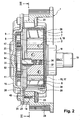
- the vane-type camshaft adjuster includes, as the drive part, an outer rotor 1 drivingly connected to a crankshaft via a drive wheel 24 and an inner rotor 2 concentrically disposed within the outer rotor 1, hereinafter referred to as a rotor, which is non-rotatably connected to a camshaft 19.
- the outer rotor 1 is in turn made up of a plurality of rotatably interconnected components.
- the outer rotor 1 comprises a stator 3, for example designed as a sheet-metal part, whose inner lateral surface 4 is provided with a plurality of radial recesses 5, each of which is delimited by radial side walls 6, 7.
- the inner circumferential surface 4 of the stator 3 is thus circumferentially extending, inner peripheral walls 27 and circumferentially extending, outer peripheral walls 28, and the inner and outer peripheral walls each interconnecting radial side walls 6, 7, subdivided.
- the stator 3 is rotatably mounted on the rotor 2 via its inner peripheral walls 27, which abut an outer circumferential surface 8 of the rotor 2.
- the stator 3 may for example be made of sheet steel by means of a chipless forming process, such as a deep drawing process.
- each pressure chamber 10 protrudes, starting from the rotor 2, radially outwardly a wing 11, whereby the pressure chambers 10 are each divided into two oppositely acting pressure chambers 12, 13, one of which precedes in the direction of rotation of the rotor 2 and the other nachumble accordingly.
- the vanes 11 are each received in axial grooves 29, which are formed in the outer circumferential surface 8 of the rotor 2.
- a wing 11 radially outwardly loading spring element is arranged, thereby causing the wings 11 of the outer peripheral wall 28 of the stator 3 sealingly abut. equally It would be possible to form the wings 11 in the form of projections integrally with the rotor 2.
- the outer rotor 1 further comprises a stator 3 and the rotor 2 pressure-tight encapsulating housing, which is composed of a cup-shaped first housing part 15 and a disk-shaped second housing part 16 connected thereto.
- the two housing parts 15, 16 may for example be made of sheet steel by means of a chipless forming process, such as a deep-drawing process.
- the first housing part 15 is provided on a side facing the camshaft 19 with a bottom surface 17, in which a through collar 18 is formed for receiving the camshaft 19.
- the stator 3 is accommodated centered within the first housing part 15.
- the inner circumferential surface 30 of the first housing part 15 is provided with radial projections 20 which engage in respective recesses between the side walls 6, 7 of the inner circumferential surface 4 of the stator 3, whereby a circumferentially positive connection between the stator 3 and the first housing part 15 is made.
- a radial first flange 21 is formed with axial bores 22.
- second housing part 16 Coaxially disposed to the first housing part 15, second housing part 16 forms a second flange 31 which is complementary to the first flange 21 of the first housing part 15 is formed. Further, the second flange 31 is provided with axial bores, which are arranged axially in alignment with the axial bores 22 of the first flange 21.
- the two housing parts 15, 16 are interconnected by connecting means, here screws 23 which engage through the aligned axial bores.
- the drive wheel 24 is rotatably connected via the screws 23, which additionally engage through holes 14 which are formed on a radially inwardly extending collar 48 of the drive wheel 24, with the two housing parts 15, 16.
- a central bore 26 is formed in the second housing part 16, which makes it possible to fasten the rotor 2 to the camshaft 19 by means of a central screw.
- the bore 26 is closed by means of a cover 25 to the outside.
- the above-mentioned axial sealing surfaces for forming the circumferentially distributed pressure chambers 10 are formed by a arranged on the opposite side of the camshaft 19 sealing plate 9 and on the facing side of the camshaft 19 through the bottom surface 17 of the first housing part 15, which the pressure chambers or Close the pressure chambers axially in a pressure-tight manner.
- the sealing plate 9 is rotatably connected to the first housing part 15.
- a radial outer circumferential surface 38 of the sealing plate 9 is provided with indentations 39 into which engage the projections 20 formed by the inner lateral surface 30 of the first housing part 15.
- the sealing plate 9 also serves to compensate for any tolerances between the two housing parts 15, 16. Alternatively, the sealing of the pressure chambers or pressure chambers could be done to the outside through the second housing part 16.
- pressure chambers 12, 13 open pressure medium lines through which pressure medium can be supplied to the pressure chambers or derived from these.
- a pressure gradient can be established between the pair of pressure chambers of each pressure chamber, which causes a pivoting of the wings 11 and thus a change in the relative rotational position of the rotor 2 to the stator 3.
- the relative rotational position between the rotor 2 and stator 3 is maintained.
- a locking device for locking rotor 2 and stator 3 is provided in a desired rotational position.
- This comprises a piston 33 received in a recess 32 of the rotor 2, which is urged by a spring element 34 in the direction of the sealing plate 9.
- the piston 33 can engage in a recess formed by the sealing plate 9 or gate, whereby a positive connection between the rotor 2 and the stator 3 rotatably connected to the sealing plate 9 is made.
- a rotation angle limiting means for setting relative Endmoslagen of rotor 2 to stator 3 is provided in the two directions of rotation.
- the sealing plate 9 is provided with an axially stepped stile 37 for the piston 33.
- the step link 37 is formed as a radial recess of the radial boundary wall 53 of a central bore 36 of the sealing plate 9.
- the central bore 36 allows attachment of the rotor 2 by means of a central screw on the camshaft 19th
- the step link 37 is composed of two mutually offset in the axial direction scenes: a greater axial distance from the camshaft 19 arranged first link 35 ("bolt gate”), which serves the positive reception of the piston 33, and one with a smaller axial distance from the camshaft 19 arranged second link 40 ("rotational angle limiting link”), which serves to set the maximum relative Endfillagen rotor 2 to stator 3 in the two directions of rotation of the rotor 2.
- the bolt gate 35 and the Drehwinkelbegrenzungskulisse 40 are separated in the axial direction by the step 41 from each other. While the bolt gate 35 is formed in the form of an opening of the sealing plate 9, the Drehwinkelbegrenzungskulisse 40 merely as axial depression of the camshaft 19 facing sealing surface 42 of the sealing plate 9 is formed.
- the radial boundary wall sections 43, 44 of the locking link 35 are located within an (imaginary) axial extension of the radial boundary wall sections 45, 46 of the rotational angle limiting link 40.
- the bolt gate 35 extends in the circumferential direction in such a way that its radial boundary wall sections 43, 44 bear against the outer surface of the piston 33 engaging in the bolt gate 35 in the circumferential direction, so that the piston accommodated in the recess 32 of the rotor 2 and engaging in the bolt gate 35 at the same time 33 is a positive connection in the circumferential direction between the rotor 2 and the stator 3 is made.
- the two radial boundary wall sections 43, 44 of the bolt gate 35 are connected to each other by a circular segment-shaped, substantially in the circumferential direction extending boundary wall portion 49.
- the cylindrical piston 33 is slidably received in the cavity 54 of a piston sleeve 51.
- the engaging in the rotational angle limiting link 40 piston sleeve 51 is in turn slidably received in the circumferential direction in a not-shown recess between the sealing plate 9 and rotor 2.
- the piston 33 engages in the locking position through the piston sleeve 51 therethrough.
- unlocking position the piston 33 engages in the piston sleeve 51.
- the piston sleeve 51 is moved with the engaging in unlocking position in it piston 33 at a change in the relative rotational position of the rotor 2 to stator 3 in the circumferential direction.
- the Drehwinkelbegrenzungskulisse 40 extends in the circumferential direction, that their radial Begrenzungswandabroughe 45, 46 of the outer surface of the same time in the recess 32 of the rotor 2 and (only) in the Drehwinkelbegrenzungskulisse engaging piston 33 are not present in the circumferential direction, but rather Form stops for the piston 33 and the intermediate piston sleeve 51 for defining respective maximum Endmoslagen from rotor 2 to stator 3.
- the outer circumferential surface 52 of the piston sleeve 51 comes to rest against the radial boundary wall sections 45, 46 of the Drehwinkelbegrenzungskulisse 40.
- the provision of the piston sleeve 51 has the advantage that when locking in Enfrontlage no frictional torque between the outer circumferential surface of the piston 33 and the radial boundary wall sections 45, 46 of the Drehwinkelbegrenzungskulisse 40 may occur, so that the piston 33 without risk of jamming / wedging safely into the bar scenery 35 can be moved.
- the piston 33 can be displaced by a displacement mechanism between a locking position, in which it engages the locking link 35, and an unlocking position, in which it (only) engages in the rotational angle limiting link 40 with the interposition of the piston sleeve 51.
- the piston 33 is urged by the spring element 34 in the bolt backdrop 35. Only in a selectable relative rotational position (base position) of the rotor 2 to the stator 3, the piston 33 can engage in the bolt gate 35.
- the bolt gate 35 communicates with at least one pressure medium line for supplying or discharging pressure medium to or from the bolt gate 35, so that an axial end face of the piston 33 can be acted upon hydraulically and the piston 33 against the spring force of the spring element 34 from the bolt gate 35 can be pressed.
- the displacement mechanism is in this case designed so that the piston 33 can only be pushed so far in the direction of its recess 32 in the rotor 2 due to hydraulic loading, that it always engages in the unlocking position in the rotational angle limiting link 40 and the engaging in the Drehwinkelbegrenzungskulisse 40 locking sleeve 51 in order to realize in cooperation with the entrained piston sleeve 51, a rotation angle limitation between the rotor 2 and stator 3.
- Fig. 4 are the leading in the rotor rotational direction, radial boundary wall sections 43, 45 of the locking link 35 and the rotational angle limiting link 40 are arranged approximately axially aligned with each other. This causes a locking of the rotor 2 in the early position, in which the wings 41 are arranged in the locking position closer to the leading edge in the rotor rotational direction side walls 6 than to the corresponding trailing side walls 7 of the pressure chambers 10.
- a spring element 47 is arranged, which is connected both to the outer rotor 1 and to the inner rotor 2. The forces exerted by the spring element 47 on the rotor 2 are directed so that the rotor 2 and stator 3 are rotated in insufficient pressure medium filling the pressure chambers in such a relative rotational position (base position), in which the piston 33 can engage in the bolt backdrop 35.
- Fig. 5 illustrates a sealing plate 9 of another embodiment of the locking device according to the invention with locking in the center position.
- the radial boundary wall sections 43, 44 of the bolt gate 35 are arranged approximately centrally in the circumferential direction between an (imaginary) axial extension of the radial boundary wall sections 45, 46 of the rotational angle limiting track 40.
- the sealing plate 9 is made of a hardenable steel, so that it can be subjected to a hardening process after shaping to ensure that the forces transmitted via the piston 33 can be reliably absorbed.
- the bar scenery 35 in 4 and 5 is formed in the form of an opening, it would equally possible that it is formed only in the form of an axial depression of the sealing surface 42 of the sealing plate 9.
- step pattern 37 in 4 and 5 formed in the sealing plate 9 it would be equally possible to form the step link in the second housing part 16 or another component of the outer rotor 1
Landscapes
- Engineering & Computer Science (AREA)
- Mechanical Engineering (AREA)
- General Engineering & Computer Science (AREA)
- Valve Device For Special Equipments (AREA)
- Valve-Gear Or Valve Arrangements (AREA)
Claims (16)
- Dispositif combiné de verrouillage et de limitation d'angle de rotation pour le verrouillage et le réglage d'une variabilité de rotation maximale d'une partie d'entraînement (1) solidaire du vilebrequin et d'une partie de sortie (2) solidaire de l'arbre à cames, réglable en rotation par rapport à celui-ci, d'un variateur d'arbre à cames pour un moteur à combustion interne, avec un verrou (33) logé dans la partie d'entraînement ou de sortie et déplaçable au moyen d'un mécanisme de déplacement, avec une coulisse de verrouillage (35) formée de manière correspondante dans l'autre partie, par laquelle le verrou (33) peut être contenu en complémentarité de forme en direction périphérique, et avec une coulisse de limitation d'angle de rotation (40) formée de manière correspondante dans l'autre partie, par laquelle le verrou (33) peut être contenu à distance en direction périphérique, dans lequel des parties de paroi de limitation essentiellement radiales (45, 46) espacées en direction périphérique servent de butées pour le verrou en vue du réglage de la variabilité de rotation maximale de la partie d'entraînement et de sortie, dans lequel la coulisse de verrouillage, la coulisse de limitation d'angle de rotation et le verrou sont disposés de telle manière que le verrou puisse être déplacé par le mécanisme de déplacement dans une position de verrouillage, dans laquelle il peut être guidé par la coulisse de verrouillage, et dans une position de déverrouillage, dans laquelle il peut être guidé par la coulisse de limitation d'angle de rotation, caractérisé en ce que la coulisse de verrouillage (35) est disposée à l'intérieur d'un prolongement en particulier axial dans la direction de déplacement du verrou de la coulisse de limitation d'angle de rotation (40).
- Dispositif combiné de verrouillage et de limitation d'angle de rotation selon la revendication 1, caractérisé en ce que la coulisse de verrouillage (35) et la coulisse de limitation d'angle de rotation (40) sont disposées avec un décalage en direction axiale.
- Dispositif combiné de verrouillage et de limitation d'angle de rotation selon l'une quelconque des revendications 1 ou 2, caractérisé en ce que la coulisse de verrouillage (35) et la coulisse de limitation d'angle de rotation (40) sont réalisées sous la forme d'une coulisse étagée (37).
- Dispositif combiné de verrouillage et de limitation d'angle de rotation selon l'une quelconque des revendications 2 ou 3, caractérisé en ce qu'une partie de paroi de limitation essentiellement radiale (44) de la coulisse de verrouillage (35), qui suit dans le sens de rotation de la partie de sortie (2), est disposée en direction périphérique plus près d'un prolongement axial d'une partie de paroi de limitation essentiellement radiale (46) de la coulisse de limitation d'angle de rotation (40), qui suit dans le sens de rotation de la partie de sortie (2), que d'un prolongement axial d'une partie de paroi de limitation essentiellement radiale (45) de la coulisse de limitation d'angle de rotation (40), qui précède dans le sens de rotation de la partie de sortie (2).
- Dispositif combiné de verrouillage et de limitation d'angle de rotation selon la revendication 4, caractérisé en ce qu'une partie de paroi de limitation essentiellement radiale (44) de la coulisse de verrouillage (35), qui suit dans le sens de rotation de la partie de sortie (2), est disposée en alignement axial avec une partie de paroi de limitation essentiellement radiale (46) de la coulisse de limitation d'angle de rotation (40), qui suit dans le sens de rotation de la partie de sortie (2).
- Dispositif combiné de verrouillage et de limitation d'angle de rotation selon l'une quelconque des revendications 2 ou 3, caractérisé en ce qu'une partie de paroi de limitation essentiellement radiale (43) de la coulisse de verrouillage (35), qui précède dans le sens de rotation de la partie de sortie (2), est disposée en direction périphérique plus près d'un prolongement axial d'une partie de paroi de limitation essentiellement radiale (45) de la coulisse de limitation d'angle de rotation (40), qui précède dans le sens de rotation de la partie de sortie (2), que d'un prolongement axial d'une partie de paroi de limitation essentiellement radiale (46) de la coulisse de limitation d'angle de rotation (40), qui suit dans le sens de rotation de la partie de sortie.
- Dispositif combiné de verrouillage et de limitation d'angle de rotation selon la revendication 6, caractérisé en ce qu'une partie de paroi de limitation essentiellement radiale (43) de la coulisse de verrouillage (35), qui précède dans le sens de rotation de la partie de sortie (2), est disposée en alignement axial avec une partie de paroi de limitation essentiellement radiale (45) de la coulisse de limitation d'angle de rotation (40), qui précède dans le sens de rotation de la partie de sortie (2).
- Dispositif combiné de verrouillage et de limitation d'angle de rotation selon l'une quelconque des revendications 2 ou 3, caractérisé en ce que la coulisse de verrouillage (35) est disposée sensiblement au milieu entre les prolongements axiaux d'une partie de paroi de limitation essentiellement radiale (46), qui suit dans le sens de rotation de la partie de sortie (2), et d'une partie de paroi de limitation essentiellement radiale (45) de la coulisse de limitation d'angle de rotation (40), qui précède dans le sens de rotation de la partie de sortie (2).
- Dispositif combiné de verrouillage et de limitation d'angle de rotation selon l'une quelconque des revendications 1 à 8, caractérisé en ce que la coulisse de verrouillage et la coulisse de limitation d'angle de rotation (35, 40) sont formées dans la partie d'entraînement (1).
- Dispositif combiné de verrouillage et de limitation d'angle de rotation selon la revendication 9, caractérisé en ce que la coulisse de verrouillage et la coulisse de limitation d'angle de rotation (35, 40) sont réalisées dans un élément d'étanchéité (9) disposé entre un composant de boîtier (16) et la partie de sortie (2).
- Dispositif combiné de verrouillage et de limitation d'angle de rotation selon la revendication 10, caractérisé en ce que la coulisse de verrouillage et la coulisse de limitation d'angle de rotation (35, 40) sont réalisées respectivement sous la forme d'un évidement radial d'un alésage central (36) de l'élément d'étanchéité (9).
- Dispositif combiné de verrouillage et de limitation d'angle de rotation selon l'une quelconque des revendications 1 à 11, caractérisé en ce que le verrou (33) est guidé par la coulisse de limitation d'angle de rotation (40) avec interposition d'un coulisseau (51) s'engageant dans la coulisse de limitation d'angle de rotation (40), le verrou (33) étant contenu, de manière déplaceable dans sa direction de déplacement, dans le coulisseau (51).
- Dispositif combiné de verrouillage et de limitation d'angle de rotation selon la revendication 12, caractérisé en ce que le coulisseau (51) est réalisé en forme de douille.
- Variateur d'arbre à cames avec un dispositif combiné de verrouillage et de limitation d'angle de rotation selon l'une quelconque des revendications 1 à 13.
- Moteur à combustion interne avec un dispositif combiné de verrouillage et de limitation d'angle de rotation selon l'une quelconque des revendications 1 à 13.
- Véhicule automobile avec un moteur à combustion interne selon la revendication 15.
Applications Claiming Priority (2)
| Application Number | Priority Date | Filing Date | Title |
|---|---|---|---|
| DE102007004184A DE102007004184A1 (de) | 2007-01-27 | 2007-01-27 | Kombinierte Verriegelungs- und Drehwinkelbegrenzungseinrichtung eines Nockenwellenverstellers |
| PCT/EP2007/064300 WO2008089876A1 (fr) | 2007-01-27 | 2007-12-20 | Dispositif combiné de verrouillage et de limitation d'angle de rotation d'un variateur d'arbre à cames |
Publications (2)
| Publication Number | Publication Date |
|---|---|
| EP2118455A1 EP2118455A1 (fr) | 2009-11-18 |
| EP2118455B1 true EP2118455B1 (fr) | 2011-10-12 |
Family
ID=39284149
Family Applications (1)
| Application Number | Title | Priority Date | Filing Date |
|---|---|---|---|
| EP07857921A Not-in-force EP2118455B1 (fr) | 2007-01-27 | 2007-12-20 | Dispositif combiné de verrouillage et de limitation d'angle de rotation d'un variateur d'arbre à cames |
Country Status (6)
| Country | Link |
|---|---|
| US (1) | US8166934B2 (fr) |
| EP (1) | EP2118455B1 (fr) |
| CN (1) | CN101600856B (fr) |
| AT (1) | ATE528487T1 (fr) |
| DE (1) | DE102007004184A1 (fr) |
| WO (1) | WO2008089876A1 (fr) |
Cited By (1)
| Publication number | Priority date | Publication date | Assignee | Title |
|---|---|---|---|---|
| DE102012206072B4 (de) * | 2011-04-18 | 2017-08-03 | Denso Corporation | Ventilsteuervorrichtung |
Families Citing this family (8)
| Publication number | Priority date | Publication date | Assignee | Title |
|---|---|---|---|---|
| DE102007056550A1 (de) * | 2007-11-23 | 2009-05-28 | Schaeffler Kg | Modular aufgebauter Nockenwellenversteller mit Ketten- oder Riemenrad |
| US8171903B2 (en) * | 2008-12-03 | 2012-05-08 | Hyundai Motor Company | Intermediate lock pin type variable valve timing unit for vehicle and continuously variable valve timing device using the same |
| DE102011085693A1 (de) * | 2011-11-03 | 2013-05-08 | Schaeffler Technologies AG & Co. KG | Nockenwellenversteller |
| DE102012206338B4 (de) * | 2012-04-18 | 2021-06-02 | Schaeffler Technologies AG & Co. KG | Nockenwellenversteller mit Stator-Deckel-Einheit zur automatischen Einstellung eines Verriegelungsspiels |
| DE102013203245A1 (de) * | 2013-02-27 | 2014-08-28 | Schaeffler Technologies Gmbh & Co. Kg | Statortopf mit Einlegescheibe zur Reduzierung des Axiallagerspiels |
| DE102014009091A1 (de) * | 2014-06-19 | 2015-12-24 | Hilite Germany Gmbh | Schwenkmotorversteller für eine Nockenwelle |
| DE102016107986A1 (de) | 2015-11-04 | 2017-05-04 | Hilite Germany Gmbh | Hydraulikventil und Pleuel mit einem Hydraulikventil |
| CN118583023B (zh) * | 2024-08-06 | 2024-10-29 | 国营川西机器厂 | 用于航空发动机主燃油泵调节器凸轮轴向位移的测量装置 |
Family Cites Families (15)
| Publication number | Priority date | Publication date | Assignee | Title |
|---|---|---|---|---|
| KR100242589B1 (ko) * | 1996-04-04 | 2000-03-02 | 와다 아끼히로 | 내연기관의 가변밸브 타이밍기구 |
| JP3918971B2 (ja) * | 1998-04-27 | 2007-05-23 | アイシン精機株式会社 | 弁開閉時期制御装置 |
| DE19860418B4 (de) | 1998-12-28 | 2008-09-11 | Schaeffler Kg | Vorrichtung zum Verändern der Steuerzeiten von Gaswechselventilen einer Brennkraftmaschine, insbesondere Nockenwellen-Verstelleinrichtung mit Flügelrad |
| JP4142204B2 (ja) * | 1999-05-19 | 2008-09-03 | 本田技研工業株式会社 | 弁作動特性可変装置 |
| JP4440384B2 (ja) | 1999-09-24 | 2010-03-24 | アイシン精機株式会社 | 弁開閉時期制御装置 |
| JP4207141B2 (ja) * | 2000-06-09 | 2009-01-14 | 株式会社デンソー | バルブタイミング調整装置 |
| JP2002122009A (ja) | 2000-08-09 | 2002-04-26 | Mitsubishi Electric Corp | バルブタイミング調整装置 |
| DE10213831A1 (de) * | 2001-03-28 | 2002-11-07 | Denso Corp | Variables Ventilsteuerzeitengerät |
| JP2002295275A (ja) * | 2001-03-29 | 2002-10-09 | Denso Corp | バルブタイミング調整装置 |
| JP3736489B2 (ja) * | 2002-03-27 | 2006-01-18 | 株式会社デンソー | バルブタイミング調整装置の制御方法 |
| JP4177197B2 (ja) * | 2003-08-08 | 2008-11-05 | 株式会社日立製作所 | 内燃機関のバルブタイミング制御装置 |
| DE10354586A1 (de) | 2003-11-21 | 2005-06-16 | Ina-Schaeffler Kg | Hydraulischer Nockenwellenversteller und Verfahren zum Betreiben desselben |
| JP2006170085A (ja) * | 2004-12-16 | 2006-06-29 | Aisin Seiki Co Ltd | 弁開閉時期制御装置及び最低トルクの設定方法 |
| EP1681442A1 (fr) * | 2005-01-18 | 2006-07-19 | Delphi Technologies, Inc. | Déphaseur d' arbre à cames pour commander le déphasage entre l'arbre à cames et la distribution |
| DE102007015064A1 (de) * | 2007-03-29 | 2008-10-02 | Schaeffler Kg | Nockenwellenversteller und Verfahren zur Einstellung einer Begrenzungsstellung für einen Nockenwellenversteller |
-
2007
- 2007-01-27 DE DE102007004184A patent/DE102007004184A1/de not_active Withdrawn
- 2007-12-20 EP EP07857921A patent/EP2118455B1/fr not_active Not-in-force
- 2007-12-20 WO PCT/EP2007/064300 patent/WO2008089876A1/fr not_active Ceased
- 2007-12-20 AT AT07857921T patent/ATE528487T1/de active
- 2007-12-20 US US12/524,505 patent/US8166934B2/en not_active Expired - Fee Related
- 2007-12-20 CN CN2007800505288A patent/CN101600856B/zh not_active Expired - Fee Related
Cited By (1)
| Publication number | Priority date | Publication date | Assignee | Title |
|---|---|---|---|---|
| DE102012206072B4 (de) * | 2011-04-18 | 2017-08-03 | Denso Corporation | Ventilsteuervorrichtung |
Also Published As
| Publication number | Publication date |
|---|---|
| EP2118455A1 (fr) | 2009-11-18 |
| WO2008089876A1 (fr) | 2008-07-31 |
| ATE528487T1 (de) | 2011-10-15 |
| US20100101516A1 (en) | 2010-04-29 |
| US8166934B2 (en) | 2012-05-01 |
| DE102007004184A1 (de) | 2008-07-31 |
| CN101600856B (zh) | 2013-06-05 |
| CN101600856A (zh) | 2009-12-09 |
Similar Documents
| Publication | Publication Date | Title |
|---|---|---|
| EP2118455B1 (fr) | Dispositif combiné de verrouillage et de limitation d'angle de rotation d'un variateur d'arbre à cames | |
| DE19914767C2 (de) | Ventilzeit-Steuerungseinrichtung | |
| DE60201949T2 (de) | Nockenwellenverstellanordnung für eine Vierzylinderbrennkraftmaschine | |
| EP2527607B1 (fr) | Dispositif de réglage de la position relative de l'angle de rotation d'un arbre à came imbriqué | |
| DE102004038252A1 (de) | Steuerventil für eine Vorrichtung zur Veränderung der Steuerzeiten einer Brennkraftmaschine | |
| EP1832723B1 (fr) | Commande de soupape pour régler la levée des soupapes dans un moteur à combustion interne | |
| DE102004036096A1 (de) | Steuerventil für eine Vorrichtung zur Veränderung der Steuerzeiten einer Brennkraftmaschine | |
| DE102008011916A1 (de) | Nockenwellenversteller mit Rasterverriegelungseinrichtung | |
| EP1896699B1 (fr) | Soupape de commande pour un dispositif de reglage variable des temps de commande de soupapes d'echange des gaz d'un moteur a combustion interne | |
| DE102007058491A1 (de) | Vorrichtung zur variablen Einstellung der Steuerzeiten von Gaswechselventilen einer Brennkraftmaschine | |
| DE112016000836T5 (de) | Nockenwellenphasenversteller | |
| DE102014212617A1 (de) | Mittenverriegelung für einen Nockenwellenversteller | |
| WO2013189621A1 (fr) | Soupape de commande d'un déphaseur d'arbre à cames | |
| DE10055334C2 (de) | Vorrichtung zur relativen Drehwinkelverstellung einer Nockenwelle einer Brennkraftmaschine zu einem Antriebsrad | |
| DE102007019920A1 (de) | Verrieglungs- und Drehwinkelbegrenzungsanordnung eines Nockenwellenverstellers | |
| DE102008051732A1 (de) | Vorrichtung zur variablen Einstellung der Steuerzeiten von Gaswechselventilen einer Brennkraftmaschine | |
| DE10339668B4 (de) | Ventilzeitsteuervorrichtung | |
| DE102012203114A1 (de) | Einlegeteil für Nockenwellenversteller mit Mittenverriegelung | |
| DE102010009393A1 (de) | Vorrichtung zur variablen Einstellung der Steuerzeiten von Gaswechselventilen einer Brennkraftmaschine | |
| EP1989404A1 (fr) | Dispositif d'ajustement variable des instants d'activation des soupapes d'un moteur a combustion interne | |
| EP3158173B1 (fr) | Déphaseur à moteur oscillant pour arbre à cames | |
| DE102015214623A1 (de) | Nockenwellenverstellvorrichtung | |
| EP2362074B1 (fr) | Dispositif destiné au calage variable des soupapes d'un moteur à combustion interne | |
| DE102004019190A1 (de) | Nockenwellenversteller | |
| DE102008011116A1 (de) | Nockenwellenversteller mit Steuerelement |
Legal Events
| Date | Code | Title | Description |
|---|---|---|---|
| PUAI | Public reference made under article 153(3) epc to a published international application that has entered the european phase |
Free format text: ORIGINAL CODE: 0009012 |
|
| 17P | Request for examination filed |
Effective date: 20090827 |
|
| AK | Designated contracting states |
Kind code of ref document: A1 Designated state(s): AT BE BG CH CY CZ DE DK EE ES FI FR GB GR HU IE IS IT LI LT LU LV MC MT NL PL PT RO SE SI SK TR |
|
| 17Q | First examination report despatched |
Effective date: 20091223 |
|
| DAX | Request for extension of the european patent (deleted) | ||
| GRAP | Despatch of communication of intention to grant a patent |
Free format text: ORIGINAL CODE: EPIDOSNIGR1 |
|
| GRAS | Grant fee paid |
Free format text: ORIGINAL CODE: EPIDOSNIGR3 |
|
| GRAA | (expected) grant |
Free format text: ORIGINAL CODE: 0009210 |
|
| RAP1 | Party data changed (applicant data changed or rights of an application transferred) |
Owner name: SCHAEFFLER TECHNOLOGIES GMBH & CO. KG |
|
| AK | Designated contracting states |
Kind code of ref document: B1 Designated state(s): AT BE BG CH CY CZ DE DK EE ES FI FR GB GR HU IE IS IT LI LT LU LV MC MT NL PL PT RO SE SI SK TR |
|
| REG | Reference to a national code |
Ref country code: GB Ref legal event code: FG4D Free format text: NOT ENGLISH |
|
| REG | Reference to a national code |
Ref country code: CH Ref legal event code: EP |
|
| REG | Reference to a national code |
Ref country code: IE Ref legal event code: FG4D |
|
| REG | Reference to a national code |
Ref country code: DE Ref legal event code: R096 Ref document number: 502007008373 Country of ref document: DE Effective date: 20111215 |
|
| REG | Reference to a national code |
Ref country code: NL Ref legal event code: VDEP Effective date: 20111012 |
|
| RAP2 | Party data changed (patent owner data changed or rights of a patent transferred) |
Owner name: SCHAEFFLER TECHNOLOGIES AG & CO. KG |
|
| REG | Reference to a national code |
Ref country code: CH Ref legal event code: PFA Owner name: SCHAEFFLER TECHNOLOGIES AG & CO. KG Free format text: SCHAEFFLER TECHNOLOGIES GMBH & CO. KG#INDUSTRIESTRASSE 1-3#91074 HERZOGENAURACH (DE) -TRANSFER TO- SCHAEFFLER TECHNOLOGIES AG & CO. KG#INDUSTRIESTRASSE 1-3#91074 HERZOGENAURACH (DE) |
|
| LTIE | Lt: invalidation of european patent or patent extension |
Effective date: 20111012 |
|
| PG25 | Lapsed in a contracting state [announced via postgrant information from national office to epo] |
Ref country code: IS Free format text: LAPSE BECAUSE OF FAILURE TO SUBMIT A TRANSLATION OF THE DESCRIPTION OR TO PAY THE FEE WITHIN THE PRESCRIBED TIME-LIMIT Effective date: 20120212 Ref country code: LT Free format text: LAPSE BECAUSE OF FAILURE TO SUBMIT A TRANSLATION OF THE DESCRIPTION OR TO PAY THE FEE WITHIN THE PRESCRIBED TIME-LIMIT Effective date: 20111012 |
|
| REG | Reference to a national code |
Ref country code: IE Ref legal event code: FD4D |
|
| PG25 | Lapsed in a contracting state [announced via postgrant information from national office to epo] |
Ref country code: GR Free format text: LAPSE BECAUSE OF FAILURE TO SUBMIT A TRANSLATION OF THE DESCRIPTION OR TO PAY THE FEE WITHIN THE PRESCRIBED TIME-LIMIT Effective date: 20120113 Ref country code: SI Free format text: LAPSE BECAUSE OF FAILURE TO SUBMIT A TRANSLATION OF THE DESCRIPTION OR TO PAY THE FEE WITHIN THE PRESCRIBED TIME-LIMIT Effective date: 20111012 Ref country code: NL Free format text: LAPSE BECAUSE OF FAILURE TO SUBMIT A TRANSLATION OF THE DESCRIPTION OR TO PAY THE FEE WITHIN THE PRESCRIBED TIME-LIMIT Effective date: 20111012 Ref country code: SE Free format text: LAPSE BECAUSE OF FAILURE TO SUBMIT A TRANSLATION OF THE DESCRIPTION OR TO PAY THE FEE WITHIN THE PRESCRIBED TIME-LIMIT Effective date: 20111012 Ref country code: LV Free format text: LAPSE BECAUSE OF FAILURE TO SUBMIT A TRANSLATION OF THE DESCRIPTION OR TO PAY THE FEE WITHIN THE PRESCRIBED TIME-LIMIT Effective date: 20111012 Ref country code: PT Free format text: LAPSE BECAUSE OF FAILURE TO SUBMIT A TRANSLATION OF THE DESCRIPTION OR TO PAY THE FEE WITHIN THE PRESCRIBED TIME-LIMIT Effective date: 20120213 |
|
| PG25 | Lapsed in a contracting state [announced via postgrant information from national office to epo] |
Ref country code: CY Free format text: LAPSE BECAUSE OF FAILURE TO SUBMIT A TRANSLATION OF THE DESCRIPTION OR TO PAY THE FEE WITHIN THE PRESCRIBED TIME-LIMIT Effective date: 20111012 |
|
| BERE | Be: lapsed |
Owner name: SCHAEFFLER TECHNOLOGIES G.M.B.H. & CO. KG Effective date: 20111231 |
|
| PG25 | Lapsed in a contracting state [announced via postgrant information from national office to epo] |
Ref country code: DK Free format text: LAPSE BECAUSE OF FAILURE TO SUBMIT A TRANSLATION OF THE DESCRIPTION OR TO PAY THE FEE WITHIN THE PRESCRIBED TIME-LIMIT Effective date: 20111012 Ref country code: CZ Free format text: LAPSE BECAUSE OF FAILURE TO SUBMIT A TRANSLATION OF THE DESCRIPTION OR TO PAY THE FEE WITHIN THE PRESCRIBED TIME-LIMIT Effective date: 20111012 Ref country code: IE Free format text: LAPSE BECAUSE OF FAILURE TO SUBMIT A TRANSLATION OF THE DESCRIPTION OR TO PAY THE FEE WITHIN THE PRESCRIBED TIME-LIMIT Effective date: 20111012 Ref country code: EE Free format text: LAPSE BECAUSE OF FAILURE TO SUBMIT A TRANSLATION OF THE DESCRIPTION OR TO PAY THE FEE WITHIN THE PRESCRIBED TIME-LIMIT Effective date: 20111012 Ref country code: MC Free format text: LAPSE BECAUSE OF NON-PAYMENT OF DUE FEES Effective date: 20111231 Ref country code: BG Free format text: LAPSE BECAUSE OF FAILURE TO SUBMIT A TRANSLATION OF THE DESCRIPTION OR TO PAY THE FEE WITHIN THE PRESCRIBED TIME-LIMIT Effective date: 20120112 Ref country code: SK Free format text: LAPSE BECAUSE OF FAILURE TO SUBMIT A TRANSLATION OF THE DESCRIPTION OR TO PAY THE FEE WITHIN THE PRESCRIBED TIME-LIMIT Effective date: 20111012 |
|
| REG | Reference to a national code |
Ref country code: CH Ref legal event code: PL |
|
| PLBE | No opposition filed within time limit |
Free format text: ORIGINAL CODE: 0009261 |
|
| STAA | Information on the status of an ep patent application or granted ep patent |
Free format text: STATUS: NO OPPOSITION FILED WITHIN TIME LIMIT |
|
| PG25 | Lapsed in a contracting state [announced via postgrant information from national office to epo] |
Ref country code: RO Free format text: LAPSE BECAUSE OF FAILURE TO SUBMIT A TRANSLATION OF THE DESCRIPTION OR TO PAY THE FEE WITHIN THE PRESCRIBED TIME-LIMIT Effective date: 20111012 Ref country code: PL Free format text: LAPSE BECAUSE OF FAILURE TO SUBMIT A TRANSLATION OF THE DESCRIPTION OR TO PAY THE FEE WITHIN THE PRESCRIBED TIME-LIMIT Effective date: 20111012 |
|
| 26N | No opposition filed |
Effective date: 20120713 |
|
| REG | Reference to a national code |
Ref country code: DE Ref legal event code: R081 Ref document number: 502007008373 Country of ref document: DE Owner name: SCHAEFFLER TECHNOLOGIES AG & CO. KG, DE Free format text: FORMER OWNER: SCHAEFFLER TECHNOLOGIES GMBH & CO. KG, 91074 HERZOGENAURACH, DE Effective date: 20120828 Ref country code: DE Ref legal event code: R081 Ref document number: 502007008373 Country of ref document: DE Owner name: SCHAEFFLER TECHNOLOGIES GMBH & CO. KG, DE Free format text: FORMER OWNER: SCHAEFFLER TECHNOLOGIES GMBH & CO. KG, 91074 HERZOGENAURACH, DE Effective date: 20120828 |
|
| PG25 | Lapsed in a contracting state [announced via postgrant information from national office to epo] |
Ref country code: CH Free format text: LAPSE BECAUSE OF NON-PAYMENT OF DUE FEES Effective date: 20111231 Ref country code: LI Free format text: LAPSE BECAUSE OF NON-PAYMENT OF DUE FEES Effective date: 20111231 Ref country code: BE Free format text: LAPSE BECAUSE OF NON-PAYMENT OF DUE FEES Effective date: 20111231 |
|
| REG | Reference to a national code |
Ref country code: DE Ref legal event code: R097 Ref document number: 502007008373 Country of ref document: DE Effective date: 20120713 |
|
| REG | Reference to a national code |
Ref country code: HU Ref legal event code: AG4A Ref document number: E014069 Country of ref document: HU |
|
| PG25 | Lapsed in a contracting state [announced via postgrant information from national office to epo] |
Ref country code: MT Free format text: LAPSE BECAUSE OF FAILURE TO SUBMIT A TRANSLATION OF THE DESCRIPTION OR TO PAY THE FEE WITHIN THE PRESCRIBED TIME-LIMIT Effective date: 20111012 |
|
| PG25 | Lapsed in a contracting state [announced via postgrant information from national office to epo] |
Ref country code: ES Free format text: LAPSE BECAUSE OF FAILURE TO SUBMIT A TRANSLATION OF THE DESCRIPTION OR TO PAY THE FEE WITHIN THE PRESCRIBED TIME-LIMIT Effective date: 20120123 |
|
| PG25 | Lapsed in a contracting state [announced via postgrant information from national office to epo] |
Ref country code: LU Free format text: LAPSE BECAUSE OF NON-PAYMENT OF DUE FEES Effective date: 20111220 |
|
| PG25 | Lapsed in a contracting state [announced via postgrant information from national office to epo] |
Ref country code: FI Free format text: LAPSE BECAUSE OF FAILURE TO SUBMIT A TRANSLATION OF THE DESCRIPTION OR TO PAY THE FEE WITHIN THE PRESCRIBED TIME-LIMIT Effective date: 20111012 |
|
| PG25 | Lapsed in a contracting state [announced via postgrant information from national office to epo] |
Ref country code: TR Free format text: LAPSE BECAUSE OF FAILURE TO SUBMIT A TRANSLATION OF THE DESCRIPTION OR TO PAY THE FEE WITHIN THE PRESCRIBED TIME-LIMIT Effective date: 20111012 |
|
| REG | Reference to a national code |
Ref country code: AT Ref legal event code: MM01 Ref document number: 528487 Country of ref document: AT Kind code of ref document: T Effective date: 20121220 |
|
| REG | Reference to a national code |
Ref country code: DE Ref legal event code: R081 Ref document number: 502007008373 Country of ref document: DE Owner name: SCHAEFFLER TECHNOLOGIES AG & CO. KG, DE Free format text: FORMER OWNER: SCHAEFFLER TECHNOLOGIES AG & CO. KG, 91074 HERZOGENAURACH, DE Effective date: 20140218 Ref country code: DE Ref legal event code: R081 Ref document number: 502007008373 Country of ref document: DE Owner name: SCHAEFFLER TECHNOLOGIES GMBH & CO. KG, DE Free format text: FORMER OWNER: SCHAEFFLER TECHNOLOGIES AG & CO. KG, 91074 HERZOGENAURACH, DE Effective date: 20140218 |
|
| PG25 | Lapsed in a contracting state [announced via postgrant information from national office to epo] |
Ref country code: AT Free format text: LAPSE BECAUSE OF NON-PAYMENT OF DUE FEES Effective date: 20121220 |
|
| REG | Reference to a national code |
Ref country code: HU Ref legal event code: GB9C Owner name: SCHAEFFLER TECHNOLOGIES GMBH & CO. KG, DE Free format text: FORMER OWNER(S): SCHAEFFLER TECHNOLOGIES GMBH & CO. KG, DE; SCHAEFFLER TECHNOLOGIES AG & CO. KG, DE Ref country code: HU Ref legal event code: FH1C Free format text: FORMER REPRESENTATIVE(S): SBGK SZABADALMI UEGYVIVOEI IRODA, HU Representative=s name: SBGK SZABADALMI UEGYVIVOEI IRODA, HU |
|
| REG | Reference to a national code |
Ref country code: DE Ref legal event code: R081 Ref document number: 502007008373 Country of ref document: DE Owner name: SCHAEFFLER TECHNOLOGIES AG & CO. KG, DE Free format text: FORMER OWNER: SCHAEFFLER TECHNOLOGIES GMBH & CO. KG, 91074 HERZOGENAURACH, DE Effective date: 20150402 |
|
| REG | Reference to a national code |
Ref country code: HU Ref legal event code: FH1C Free format text: FORMER REPRESENTATIVE(S): SBGK SZABADALMI UEGYVIVOEI IRODA, HU Representative=s name: SBGK SZABADALMI UEGYVIVOEI IRODA, HU Ref country code: HU Ref legal event code: GB9C Owner name: SCHAEFFLER TECHNOLOGIES AG & CO. KG, DE Free format text: FORMER OWNER(S): SCHAEFFLER TECHNOLOGIES GMBH & CO. KG, DE; SCHAEFFLER TECHNOLOGIES AG & CO. KG, DE; SCHAEFFLER TECHNOLOGIES GMBH & CO. KG, DE |
|
| REG | Reference to a national code |
Ref country code: FR Ref legal event code: PLFP Year of fee payment: 9 |
|
| REG | Reference to a national code |
Ref country code: FR Ref legal event code: PLFP Year of fee payment: 10 |
|
| REG | Reference to a national code |
Ref country code: FR Ref legal event code: PLFP Year of fee payment: 11 |
|
| PGFP | Annual fee paid to national office [announced via postgrant information from national office to epo] |
Ref country code: FR Payment date: 20171226 Year of fee payment: 11 |
|
| PGFP | Annual fee paid to national office [announced via postgrant information from national office to epo] |
Ref country code: GB Payment date: 20171228 Year of fee payment: 11 |
|
| PGFP | Annual fee paid to national office [announced via postgrant information from national office to epo] |
Ref country code: IT Payment date: 20171222 Year of fee payment: 11 Ref country code: HU Payment date: 20180209 Year of fee payment: 11 |
|
| GBPC | Gb: european patent ceased through non-payment of renewal fee |
Effective date: 20181220 |
|
| PG25 | Lapsed in a contracting state [announced via postgrant information from national office to epo] |
Ref country code: FR Free format text: LAPSE BECAUSE OF NON-PAYMENT OF DUE FEES Effective date: 20181231 Ref country code: IT Free format text: LAPSE BECAUSE OF NON-PAYMENT OF DUE FEES Effective date: 20181220 |
|
| PG25 | Lapsed in a contracting state [announced via postgrant information from national office to epo] |
Ref country code: HU Free format text: LAPSE BECAUSE OF NON-PAYMENT OF DUE FEES Effective date: 20181221 |
|
| PG25 | Lapsed in a contracting state [announced via postgrant information from national office to epo] |
Ref country code: GB Free format text: LAPSE BECAUSE OF NON-PAYMENT OF DUE FEES Effective date: 20181220 |
|
| PGFP | Annual fee paid to national office [announced via postgrant information from national office to epo] |
Ref country code: DE Payment date: 20220217 Year of fee payment: 15 |
|
| P01 | Opt-out of the competence of the unified patent court (upc) registered |
Effective date: 20230522 |
|
| REG | Reference to a national code |
Ref country code: DE Ref legal event code: R119 Ref document number: 502007008373 Country of ref document: DE |
|
| PG25 | Lapsed in a contracting state [announced via postgrant information from national office to epo] |
Ref country code: DE Free format text: LAPSE BECAUSE OF NON-PAYMENT OF DUE FEES Effective date: 20230701 |