EP2122128B1 - Turbinenrad - Google Patents
Turbinenrad Download PDFInfo
- Publication number
- EP2122128B1 EP2122128B1 EP08709169A EP08709169A EP2122128B1 EP 2122128 B1 EP2122128 B1 EP 2122128B1 EP 08709169 A EP08709169 A EP 08709169A EP 08709169 A EP08709169 A EP 08709169A EP 2122128 B1 EP2122128 B1 EP 2122128B1
- Authority
- EP
- European Patent Office
- Prior art keywords
- shroud
- region
- moving blades
- gap
- circumferential direction
- Prior art date
- Legal status (The legal status is an assumption and is not a legal conclusion. Google has not performed a legal analysis and makes no representation as to the accuracy of the status listed.)
- Active
Links
Images


Classifications
-
- F—MECHANICAL ENGINEERING; LIGHTING; HEATING; WEAPONS; BLASTING
- F01—MACHINES OR ENGINES IN GENERAL; ENGINE PLANTS IN GENERAL; STEAM ENGINES
- F01D—NON-POSITIVE DISPLACEMENT MACHINES OR ENGINES, e.g. STEAM TURBINES
- F01D5/00—Blades; Blade-carrying members; Heating, heat-insulating, cooling or antivibration means on the blades or the members
- F01D5/12—Blades
- F01D5/22—Blade-to-blade connections, e.g. for damping vibrations
- F01D5/225—Blade-to-blade connections, e.g. for damping vibrations by shrouding
-
- F—MECHANICAL ENGINEERING; LIGHTING; HEATING; WEAPONS; BLASTING
- F01—MACHINES OR ENGINES IN GENERAL; ENGINE PLANTS IN GENERAL; STEAM ENGINES
- F01D—NON-POSITIVE DISPLACEMENT MACHINES OR ENGINES, e.g. STEAM TURBINES
- F01D5/00—Blades; Blade-carrying members; Heating, heat-insulating, cooling or antivibration means on the blades or the members
- F01D5/12—Blades
- F01D5/22—Blade-to-blade connections, e.g. for damping vibrations
-
- F—MECHANICAL ENGINEERING; LIGHTING; HEATING; WEAPONS; BLASTING
- F01—MACHINES OR ENGINES IN GENERAL; ENGINE PLANTS IN GENERAL; STEAM ENGINES
- F01D—NON-POSITIVE DISPLACEMENT MACHINES OR ENGINES, e.g. STEAM TURBINES
- F01D7/00—Rotors with blades adjustable in operation; Control thereof
-
- F—MECHANICAL ENGINEERING; LIGHTING; HEATING; WEAPONS; BLASTING
- F02—COMBUSTION ENGINES; HOT-GAS OR COMBUSTION-PRODUCT ENGINE PLANTS
- F02B—INTERNAL-COMBUSTION PISTON ENGINES; COMBUSTION ENGINES IN GENERAL
- F02B39/00—Component parts, details, or accessories relating to, driven charging or scavenging pumps, not provided for in groups F02B33/00 - F02B37/00
-
- F—MECHANICAL ENGINEERING; LIGHTING; HEATING; WEAPONS; BLASTING
- F02—COMBUSTION ENGINES; HOT-GAS OR COMBUSTION-PRODUCT ENGINE PLANTS
- F02C—GAS-TURBINE PLANTS; AIR INTAKES FOR JET-PROPULSION PLANTS; CONTROLLING FUEL SUPPLY IN AIR-BREATHING JET-PROPULSION PLANTS
- F02C6/00—Plural gas-turbine plants; Combinations of gas-turbine plants with other apparatus; Adaptations of gas-turbine plants for special use
- F02C6/04—Gas-turbine plants providing heated or pressurised working fluid for other apparatus, e.g. without mechanical power output
- F02C6/10—Gas-turbine plants providing heated or pressurised working fluid for other apparatus, e.g. without mechanical power output supplying working fluid to a user, e.g. a chemical process, which returns working fluid to a turbine of the plant
- F02C6/12—Turbochargers, i.e. plants for augmenting mechanical power output of internal-combustion piston engines by increase of charge pressure
Definitions
- the invention relates to the field of turbomachines, in particular exhaust gas turbocharger for supercharged internal combustion engines.
- It relates to a turbine wheel with a plurality of blades, which each have at their free ends shroud segments.
- Axial turbines thermal turbomachines such as gas turbines or turbines exhaust gas turbochargers, have a plurality of blades, which are arranged on a hub which is rotatably mounted about a shaft.
- the blades often have at their radially outer, free ends shrouds - in technical language called "Shroud" - on.
- a shroud is composed of individual segments, which are integrally connected to one blade.
- the segments are braced against each other by a torsional bias of the blades during assembly or in operation by the natural unwinding of the blades under the influence of centrifugal force.
- the function of the shrouds is to improve the thermodynamic efficiency by minimizing the gap losses, as well as in the optimization of the vibration behavior by their damping and stiffening effect.
- FIG US 5,593,282 An exemplary form of transition between the shroud segments of adjacently disposed gas turbine rotor blades is in FIG US 5,593,282 .
- Fig. 4 displayed.
- EP 1 724 441 there is disclosed a junction between the shroud segments of adjacently disposed blades of a turbine wheel which is divided into a contact region and a gap region, wherein the contact region and gap region are disposed radially at a height.
- the object of the present invention is to design the transition between the shroud segments adjacent turbine blades arranged so that the requirements in terms of thermodynamics, durability, surface pressure, assembly and manufacturing can be met.
- the transition between the shroud segments adjacent arranged blades of a turbine wheel is divided into two areas, a simple, inexpensive to be processed contact area and a - arbitrarily complicated - cast residual area.
- the shroud is in the radial direction, so seen over the blade height, divided into two levels.
- the radially outer, upper plane assumes the function of the mechanical bond between the blades in the contact area.
- the shroud segments of the adjacent blades are in contact in this area.
- the lower level of the shroud takes over the function of the flow guide, in particular the reduction of overflows on the blade tip.
- the shroud seen in the flow direction is advantageously wider than in the contact area.
- the transition to the adjacently located blades in this plane is generally oriented differently than in the contact region for flow and mountability considerations. Since no frictional connection is required in this plane, the shaping of the surface of the shroud segments are realized by casting. To compensate for the casting tolerances of this contact area can be designed as a clearance.
- the power transmission takes place between the blade ends.
- the remaining region of the transition has a gap between the shroud segments of the respective rotor blades arranged adjacent to one another so that contact between the rotor blades does not occur in this region.
- the contact area is provided with a simple surface geometry, so that it is easy to machine mechanically.
- the transition in the region of the gap, can have a more complex, in particular non-linear, surface profile, which is advantageously already formed in the casting mold during the production of the cast blank of the rotor blades.
- the inner area of the shroud which is not required for the contacting, does not contribute to the transmission of force between the shroud segments of the rotor blades. Its function consists essentially in the reduction of thermodynamic losses due to overflow of the blade tip.
- the angular position of the surface in the contact region is essentially determined by boundary conditions of the mechanics and the mountability.
- the contact surfaces must be machined due to the high dimensional stability requirements, e.g. be sanded. For cost-effective processing, they can be executed as flat surfaces.
- Fig. 1 shows a portion of the blades 10 of an axial turbine of a turbocharger.
- the blades are arranged with blade roots 14 in a blade carrier, the hub of the turbine wheel.
- the hub of the turbine wheel is rotatably mounted on a shaft about an axis.
- the terms “radial”, “axial” and “circumferentially” used here refer to this axis.
- the blade roots are formed fir tree-shaped and inserted in the axial direction in the same shape shaped grooves and secured axially.
- the blades have an aerodynamically shaped blade body 11, which is the flow, so the hot exhaust gases, exposed.
- the rotor blades At their radially outer, free ends, the rotor blades have a shroud which projects at least in sections over the blade body in the axial direction.
- the shroud is divided into many short segments 12 which are each integrally connected to a blade.
- the shroud of the rotor blades designed according to the invention has, radially outside the segments extending in the axial direction, a second, axially shorter region 13, which serves to connect the individual rotor blades to one another.
- the function of the radially inner shroud region lies essentially in the reduction of the thermodynamic losses due to overflow of the blade tip.
- a gap 19 is present in the radially inner region of the shroud segments 12 between in each case two shroud segments arranged adjacent to one another.
- the radially outer shroud segments as is out Fig. 2 can be seen, pressed together seamlessly.
- the transitions of the shroud segments are thus subdivided into a contact region and a gap region.
- each shroud segment-in the circumferential direction at both ends- has an easily machinable contact surface 15.
- This is advantageously a single, flat surface or then it is composed of a few, flat surfaces. Thanks to its simple geometric shape, the contact area of each blade can be machined in a simple way, for example by grinding or milling.
- the surface 16 may have an arbitrarily complex shape, so that, for example, a fluidically optimized transition can be formed.
- This area of the transition can already be made when casting the blade in its final form.
- the molding during casting is considerably less expensive than the subsequent mechanical creation of the complex transitional area. Thanks to the existing gap, the deviations from the intended surface course that result in the case of complex casting molds can be tolerated, so that, as a rule, post-processing of this area can be completely dispensed with.
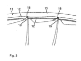
- Fig. 3 shows the group of blades in the axial direction. Clearly, the gap 19 between the axially protruding shroud segments 12 can be seen.
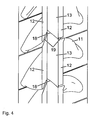
- Fig. 4 shows the blades and the shroud viewed from radially outside to inside. Again, the gap 19 between the axially outer shroud segments 12 can be seen, as well as the circumferentially closely pressed together inner portions 13 of the shroud.
Landscapes
- Engineering & Computer Science (AREA)
- Mechanical Engineering (AREA)
- General Engineering & Computer Science (AREA)
- Chemical & Material Sciences (AREA)
- Combustion & Propulsion (AREA)
- Chemical Kinetics & Catalysis (AREA)
- General Chemical & Material Sciences (AREA)
- Supercharger (AREA)
- Turbine Rotor Nozzle Sealing (AREA)
Description
- Die Erfindung bezieht sich auf das Gebiet der Strömungsmaschinen, insbesondere Abgasturbolader für aufgeladene Brennkraftmaschinen.
- Sie betrifft ein Turbinenrad mit einer Vielzahl von Laufschaufeln, welche jeweils an ihren freien Enden Deckband-Segmente aufweisen.
- Axialturbinen thermischer Strömungsmaschinen, etwa Gasturbinen oder Turbinen von Abgasturboladern, weisen eine Vielzahl von Laufschaufeln auf, welche auf einer Nabe angeordnet sind, welche um eine Welle drehbar gelagert ist. Die Laufschaufeln weisen an ihren radial äusseren, freien Enden häufig Deckbänder - in der Fachsprache "Shroud" genannt - auf. Ein Deckband setzt sich aus einzelnen Segmenten zusammen, die mit jeweils einer Laufschaufel integral verbunden sind.
- Die Segmente werden durch eine Torsionsvorspannung der Schaufeln bei der Montage oder im Betrieb durch die natürliche Entwindung der Schaufeln unter Fliehkrafteinfluss gegeneinander verspannt. Die Funktion der Deckbänder besteht in der Verbesserung des thermodynamischen Wirkungsgrades durch Minimierung der Spaltverluste, sowie in der Optimierung des Schwingungsverhaltens durch ihre dämpfende und versteifende Wirkung.
- Die Gestaltung des Übergangs zwischen den Deckband-Segmenten zweier benachbart angeordneter Laufschaufeln erfolgt nach verschiedenen Kriterien in Bezug auf Thermodynamik, Betriebsfestigkeit, Flächenpressung, Montierbarkeit und Fertigung. Die optimale Form des Übergangs zwischen den Deckband-Segmenten ist dabei aufgrund der genannten Auslegungskriterien oft so kompliziert, dass sie nur mit aufwändigen Fertigungsverfahren hergestellt werden kann. Im Vergleich zu einfachen Flächen, die beispielsweise mit eindimensionalen Schleifvorgängen bearbeitet werden können, kann das bei der Fertigung gegossener Laufschaufeln zu erheblichen Mehrkosten führen.
- Eine beispielhafte Form eines Übergangs zwischen den Deckband-Segmenten benachbart angeordneter Laufschaufeln von Gasturbinen ist in
US 5,593,282 ,Fig. 4 abgebildet. - In
EP 1 724 441 ist ein Übergang zwischen den Deckband-Segmenten benachbart angeordneter Laufschaufeln eines Turbinenrades offenbart, welcher in einen Kontaktbereich und einen Spaltbereich unterteilt ist, wobei Kontaktbereich und Spaltbereich radial auf einer Höhe angeordnet sind. - Die Aufgabe der vorliegenden Erfindung besteht darin, den Übergang zwischen den Deckband-Segmenten benachbart angeordneter Laufschaufeln eines Turbinenrades derart zu gestalten, dass die Anforderungen in Bezug auf Thermodynamik, Betriebsfestigkeit, Flächenpressung, Montierbarkeit und Fertigung erfüllt werden können.
- Erfindungsgemäss wird hierfür der Übergang zwischen den Deckband-Segmenten benachbart angeordneter Laufschaufeln eines Turbinenrades in zwei Bereiche aufgeteilt, einen einfachen, kostengünstig zu bearbeitenden Kontaktbereich und einen - beliebig komplizierten - gegossenen Restbereich. Das Deckband ist dabei in radialer Richtung, also über die Schaufelhöhe gesehen, in zwei Ebenen aufgeteilt. Die radial äussere, obere Ebene übernimmt im Kontaktbereich die Funktion der mechanischen Bindung zwischen den Schaufeln. Die Deckband-Segmente der benachbarten Schaufeln stehen in diesem Bereich in Kontakt.
- Die untere Ebene des Deckbandes übernimmt die Funktion der Strömungsführung, insbesondere der Verminderung von Überströmungen an der Schaufelspitze. In diesem Bereich ist das Deckband in Strömungsrichtung gesehen vorteilhafterweise breiter als im Kontaktbereich. Der Übergang zu den benachbart angeordneten Laufschaufeln in dieser Ebene ist aus Strömungs- und Montierbarkeitsüberlegungen im allgemeinen anders orientiert als im Kontaktbereich. Da in dieser Ebene keine kraftschlüssige Verbindung erforderlich ist, kann die Formung der Oberfläche der Deckband-Segmente giesstechnisch realisiert werden. Zur Kompensation der Gusstoleranzen kann dieser Kontaktbereich als Spielpassung ausgelegt werden.
- Im Kontaktbereich, welcher in axialer Richtung vorteilhafterweise im mittleren Bereich des Deckbandes angeordnet ist, erfolgt die Kraftübertragung zwischen den Laufschaufel-Enden. Der Restbereich des Übergangs, weist einen Spalt zwischen den Deckband-Segmenten der jeweils zueinander benachbart angeordneten Laufschaufeln auf, so dass es in diesem Bereich zu keinem Kontakt zwischen den Laufschaufeln kommt.
- Erfindungsgemäss wird der Kontaktbereich mit einer einfachen Oberflächengeometrie ausgestattet, so dass er einfach mechanisch zu bearbeiten ist. Im Bereich des Spaltes hingegen, kann der Übergang einen komplexeren, insbesondere nichtlinearen Oberflächenverlauf aufweisen, welcher vorteilhafterweise bereits in der Gussform beim Herstellen des Gussrohlings der Laufschaufeln geformt wird. Der nicht für die Kontaktierung benötigte innere Bereich des Deckbandes liefert keinen Beitrag zur Kraftübertragung zwischen den Deckband-Segmenten der Laufschaufeln. Seine Funktion besteht im wesentlichen in der Reduktion der thermodynamischen Verluste durch Überströmung der Schaufelspitze.
- Die Winkellage der Oberfläche im Kontaktbereich ist im wesentlichen durch Randbedingungen der Mechanik und der Montierbarkeit bestimmt. Die Kontaktflächen müssen aufgrund der hohen Masshaltigkeitsanforderungen mechanisch bearbeitet, z.B. geschliffen, werden. Für eine kostengünstige Bearbeitung können sie als ebene Flächen ausgeführt werden.
- Weitere Vorteile ergeben sich aus den abhängigen Ansprüchen.
- Kurze Beschreibung der Zeichnungen
- Anschliessend sind anhand der Zeichnungen Ausführungsformen des erfindungsgemässen Übergangs zwischen den Deckband-Segmenten benachbart angeordneter Laufschaufeln eines Turbinenrades beschrieben. Hierbei zeigt
- Fig. 1
- eine isometrische Ansicht - schief zur Achse, radial nach aussen - auf eine Gruppe von Laufschaufeln, welche erfindungsgemäss aneinander gereiht sind,
- Fig. 2
- eine isometrische Ansicht - schief zur Achse, radial nach innen - auf die Laufschaufelgruppe nach
Fig. 1 , - Fig. 3
- eine isometrische Ansicht - in axialer Richtung - auf die Laufschaufelgruppe nach
Fig. 1 , und - Fig. 4
- eine isometrische Ansicht - senkrecht zur Achse, radial nach innen - auf die Laufschaufelgruppe nach
Fig. 1 . -
Fig. 1 zeigt einen Teil der Laufschaufeln 10 einer Axialturbine eines Turboladers. Die Laufschaufeln sind mit Schaufelfüssen 14 in einem Schaufelträger, der Nabe des Turbinenrades, angeordnet. Die Nabe des Turbinenrades ist auf einer Welle um eine Achse drehbar gelagert. Die hier verwendeten Begriffe "radial", "axial" und "in Umfangsrichtung" beziehen sich auf diese Achse. In der Regel sind die Schaufelfüsse tannenbaumförmig ausgebildet und in axialer Richtung in gegengleich geformten Nuten eingeschoben und axial gesichert. Die Laufschaufeln weisen einen aerodynamisch geformten Schaufelkörper 11 auf, welcher der Strömung, also den heissen Abgasen, ausgesetzt ist. An ihren radial äusseren, freien Enden weisen die Laufschaufeln ein die Schaufelkörper in axialer Richtung zumindest abschnittsweise überragendes Deckband auf. Das Deckband ist in viele kurze Segmente 12 unterteilt, welche jeweils mit einer Laufschaufel integral verbunden sind. Das Deckband der erfindungsgemäss ausgestalteten Laufschaufeln weist radial ausserhalb der sich in axialer Richtung erstreckenden Segmente einen zweiten, axial kürzer ausgebildete Bereich 13 auf, welcher der Verbindung der einzelnen Laufschaufeln untereinander dient. Die Funktion des radial inneren Deckbandbereichs liegt im wesentlichen in der Reduktion der thermodynamischen Verluste durch Überströmung der Schaufelspitze. - Wie aus der
Fig. 1 hervorgeht, ist im radial inneren Bereich der Deckband-Segmente 12 zwischen jeweils zwei benachbart zueinander angeordneten Deckband-Segmenten ein Spalt 19 vorhanden. Dagegen sind die radial äusseren Deckband-Segmente, wie dies ausFig. 2 ersichtlich ist, lückenlos aneinandergepresst. Erfindungsgemäss sind somit die Übergänge der Deckband-Segmente in einen Kontaktbereich und einen Spaltbereich unterteilt. - Im Kontaktbereich weist jedes Deckband-Segment - in Umfangsrichtung an beiden Enden - eine einfach zu bearbeitende Kontaktfläche 15 auf. Diese ist vorteilhafterweise eine einzelne, ebene Fläche oder dann setzt sie sich aus einigen wenigen, ebenen Flächen zusammen. Der Kontaktbereich jeder Laufschaufel lässt sich somit, dank der einfachen geometrischen Form, auf einfach weise mechanisch bearbeiten, beispielsweise schleifen oder fräsen.
- Im Spaltbereich dagegen kann die Oberfläche 16 eine beliebig komplexe Form aufweisen, so dass beispielsweise ein strömungstechnisch optimierter Übergang geformt werden kann. Dieser Bereich des Übergangs kann bereits beim Giessen der Laufschaufel in seiner endgültigen Form hergestellt werden. Die Formgebung beim Giessen ist erheblich kostengünstiger als das nachträgliche mechanische Erstellen des komplexen Übergangsbereichs. Dank des vorhandenen Spalts können die sich bei komplexen Giessformen ergebenden Abweichungen von dem vorgesehenen Oberflächenverlauf toleriert werden, so dass in der Regel gänzlich auf eine Nachbearbeitung dieses Bereichs verzichtet werden kann.
-
Fig. 3 zeigt die Gruppe von Laufschaufeln in axialer Richtung. Deutlich ist der Spalt 19 zwischen den axial hervorstehenden Deckband-Segmenten 12 zu sehen. -
Fig. 4 zeigt die Laufschaufeln und das Deckband von radial aussen nach innen betrachtet. Wiederum ist der Spalt 19 zwischen den axial äusseren Deckband-Segmenten 12 zu sehen, sowie die in Umfangsrichtung eng aneinandergepressten inneren Bereiche 13 des Deckbandes. -
- 10
- Laufschaufel
- 11
- Schaufelkörper
- 12
- Deckband - Innenbereich
- 13
- Deckband - Aussenbereich
- 14
- Schaufelfuss
- 15
- Kontaktfläche
- 16
- Oberflächenverlauf im Spaltbereich
- 18
- Kontaktbereich
- 19
- Spaltbereich
Claims (5)
- Turbinenrad, umfassend eine Vielzahl von Laufschaufeln (10), welche auf einer um eine Achse drehbaren Nabe angeordnet sind und welche jeweils an ihren radial äusseren Enden, Deckband-Segmente (12, 13) aufweisen, welche, in Umfangsrichtung aneinandergereiht, ein ringförmiges Deckband bilden, wobei der Übergang zwischen zwei benachbart angeordneten Laufschaufeln im Bereich des Deckbands in einen Kontaktbereich (18) und einen Spaltbereich (19) unterteilt ist, wobei im Kontaktbereich (18) die Deckband-Segmente (13) der jeweiligen Laufschaufeln in Umfangsrichtung aneinandergepresst sind, und im Spaltbereich (19) zwischen den Deckband-Segmenten (12) der jeweiligen Laufschaufeln in Umfangsrichtung ein Spalt vorhanden ist,
dadurch gekennzeichnet, dass
der Kontaktbereich (18) radial ausserhalb des Spaltbereichs (19) angeordnet ist, derart dass sich in Umfangsrichtung ein radial aussen liegendes Deckband aus in Umfangsrichtung zusammengepressten Deckband-Segmenten (12) ergibt und radial innerhalb davon sich ein in Umfangsrichtung durch Spalte getrenntes Deckband erstreckt. - Turbinenrad nach Anspruch 1, dadurch gekennzeichnet, dass die Laufschaufeln im Kontaktbereich (18) eine mechanisch bearbeitete Kontaktfläche (15) aufweisen und im Spaltbereich (19) mechanisch unbehandelt sind.
- Turbinenrad nach einem der Ansprüche 1 oder 2, dadurch gekennzeichnet, dass die Laufschaufeln im Kontaktbereich (18) eine ebene Kontaktfläche (15) und im Spaltbereich (19) einen nichtlinearen Oberflächenverlauf (16) aufweisen.
- Turbine eines Abgasturboladers, umfassend ein Turbinenrad nach einem der vorangehenden Ansprüche.
- Abgasturbolader, umfassend eine Turbine nach Anspruch 4.
Priority Applications (1)
| Application Number | Priority Date | Filing Date | Title |
|---|---|---|---|
| EP08709169A EP2122128B1 (de) | 2007-02-21 | 2008-02-21 | Turbinenrad |
Applications Claiming Priority (3)
| Application Number | Priority Date | Filing Date | Title |
|---|---|---|---|
| EP07405053A EP1961918A1 (de) | 2007-02-21 | 2007-02-21 | Turbinenrad |
| EP08709169A EP2122128B1 (de) | 2007-02-21 | 2008-02-21 | Turbinenrad |
| PCT/EP2008/052140 WO2008101994A1 (de) | 2007-02-21 | 2008-02-21 | Turbinenrad |
Publications (2)
| Publication Number | Publication Date |
|---|---|
| EP2122128A1 EP2122128A1 (de) | 2009-11-25 |
| EP2122128B1 true EP2122128B1 (de) | 2011-05-11 |
Family
ID=38109574
Family Applications (2)
| Application Number | Title | Priority Date | Filing Date |
|---|---|---|---|
| EP07405053A Withdrawn EP1961918A1 (de) | 2007-02-21 | 2007-02-21 | Turbinenrad |
| EP08709169A Active EP2122128B1 (de) | 2007-02-21 | 2008-02-21 | Turbinenrad |
Family Applications Before (1)
| Application Number | Title | Priority Date | Filing Date |
|---|---|---|---|
| EP07405053A Withdrawn EP1961918A1 (de) | 2007-02-21 | 2007-02-21 | Turbinenrad |
Country Status (6)
| Country | Link |
|---|---|
| EP (2) | EP1961918A1 (de) |
| JP (1) | JP5102315B2 (de) |
| KR (1) | KR101442868B1 (de) |
| CN (1) | CN101617102B (de) |
| AT (1) | ATE509188T1 (de) |
| WO (1) | WO2008101994A1 (de) |
Families Citing this family (2)
| Publication number | Priority date | Publication date | Assignee | Title |
|---|---|---|---|---|
| DE102010031213A1 (de) * | 2010-07-12 | 2012-01-12 | Man Diesel & Turbo Se | Rotor einer Turbomaschine |
| DE102014005852A1 (de) | 2014-04-22 | 2015-10-22 | Mtu Friedrichshafen Gmbh | Turbinenschaufel |
Family Cites Families (8)
| Publication number | Priority date | Publication date | Assignee | Title |
|---|---|---|---|---|
| GB2032535A (en) * | 1978-07-25 | 1980-05-08 | Rolls Royce | Overlapping cantilevers |
| DE3802741C2 (de) * | 1988-01-30 | 1997-02-13 | Asea Brown Boveri | Verfahren zur Verspannung von Schaufeln |
| JPH0326801A (ja) * | 1989-06-23 | 1991-02-05 | Hitachi Ltd | 動翼カバー |
| DE10014189A1 (de) * | 2000-03-23 | 2001-09-27 | Alstom Power Nv | Befestigung der Beschaufelung einer Strömungsmaschine |
| EP1462610A1 (de) * | 2003-03-28 | 2004-09-29 | Siemens Aktiengesellschaft | Laufschaufelreihe für Strömungsmaschinen |
| US7001152B2 (en) * | 2003-10-09 | 2006-02-21 | Pratt & Wiley Canada Corp. | Shrouded turbine blades with locally increased contact faces |
| JP4284204B2 (ja) * | 2004-02-13 | 2009-06-24 | 株式会社東芝 | タービン動翼組立体 |
| US7270518B2 (en) * | 2005-05-19 | 2007-09-18 | General Electric Company | Steep angle turbine cover buckets having relief grooves |
-
2007
- 2007-02-21 EP EP07405053A patent/EP1961918A1/de not_active Withdrawn
-
2008
- 2008-02-21 AT AT08709169T patent/ATE509188T1/de active
- 2008-02-21 KR KR1020097015528A patent/KR101442868B1/ko active Active
- 2008-02-21 JP JP2009550292A patent/JP5102315B2/ja active Active
- 2008-02-21 WO PCT/EP2008/052140 patent/WO2008101994A1/de not_active Ceased
- 2008-02-21 EP EP08709169A patent/EP2122128B1/de active Active
- 2008-02-21 CN CN2008800055632A patent/CN101617102B/zh active Active
Also Published As
| Publication number | Publication date |
|---|---|
| EP2122128A1 (de) | 2009-11-25 |
| JP5102315B2 (ja) | 2012-12-19 |
| WO2008101994A1 (de) | 2008-08-28 |
| CN101617102A (zh) | 2009-12-30 |
| CN101617102B (zh) | 2012-05-30 |
| KR101442868B1 (ko) | 2014-09-23 |
| KR20090121276A (ko) | 2009-11-25 |
| JP2010519455A (ja) | 2010-06-03 |
| EP1961918A1 (de) | 2008-08-27 |
| ATE509188T1 (de) | 2011-05-15 |
Similar Documents
| Publication | Publication Date | Title |
|---|---|---|
| DE69523026T2 (de) | Kompressor Rotornabe | |
| EP2147216B1 (de) | Abgasturbolader | |
| EP2179143B1 (de) | Spaltkühlung zwischen brennkammerwand und turbinenwand einer gasturbinenanlage | |
| EP3999716B1 (de) | Laufschaufel für eine strömungsmaschine, zugehöriges turbinenmodul und verwendung derselben | |
| EP2294286B1 (de) | Rotor und laufschaufeln mit deckband einer strömungsmaschine | |
| EP2818724B1 (de) | Strömungsmaschine und Verfahren | |
| EP3467261B1 (de) | Verfahren zum herstellen eines tandem-leitschaufelsegments | |
| WO2002090724A1 (de) | Mantelring | |
| EP3682092B1 (de) | Abgasturbine mit diffusor | |
| EP2728122A1 (de) | Dichtungsträgerfixierung für eine Strömungsmaschine | |
| EP2411631B1 (de) | Dichtplatte und Laufschaufelsystem | |
| EP2762684A1 (de) | Dichtungsträger aus Titanaluminid für eine Strömungsmaschine | |
| EP1970535A1 (de) | Deckbandverbindung einer Turbinenschaufel | |
| EP2122128B1 (de) | Turbinenrad | |
| EP3699399B1 (de) | Schaufel für eine schnelllaufende turbinenstufe mit einzelnem dichtelement | |
| DE102016124147B4 (de) | Innenkühlkonfigurationen in Turbinenrotorschaufeln | |
| EP2607626A1 (de) | Turbomaschine und Turbomaschinenstufe | |
| DE102009052314A1 (de) | Dichtanordnung für eine Gasturbine und eine derartige Gasturbine | |
| DE202012009739U1 (de) | Integral gegossenes Turbinenrad | |
| EP1705339B1 (de) | Rotorwelle, insbesondere für eine Gasturbine | |
| EP3327258A1 (de) | Eintrittsleitrad für eine turbomaschine | |
| WO2016087153A1 (de) | Rotor, axialverdichter, verfahren zur montage | |
| EP4227489A1 (de) | Leitschaufel für eine strömungsmaschine | |
| DE102009023840A1 (de) | Rotor einer Strömungsmaschine mit separatem Deckband | |
| EP4496938B1 (de) | Düsenring für eine radialturbine, abgasturbine und abgasturbolader |
Legal Events
| Date | Code | Title | Description |
|---|---|---|---|
| PUAI | Public reference made under article 153(3) epc to a published international application that has entered the european phase |
Free format text: ORIGINAL CODE: 0009012 |
|
| 17P | Request for examination filed |
Effective date: 20090629 |
|
| AK | Designated contracting states |
Kind code of ref document: A1 Designated state(s): AT BE BG CH CY CZ DE DK EE ES FI FR GB GR HR HU IE IS IT LI LT LU LV MC MT NL NO PL PT RO SE SI SK TR |
|
| 17Q | First examination report despatched |
Effective date: 20100401 |
|
| DAX | Request for extension of the european patent (deleted) | ||
| GRAP | Despatch of communication of intention to grant a patent |
Free format text: ORIGINAL CODE: EPIDOSNIGR1 |
|
| GRAS | Grant fee paid |
Free format text: ORIGINAL CODE: EPIDOSNIGR3 |
|
| GRAA | (expected) grant |
Free format text: ORIGINAL CODE: 0009210 |
|
| AK | Designated contracting states |
Kind code of ref document: B1 Designated state(s): AT BE BG CH CY CZ DE DK EE ES FI FR GB GR HR HU IE IS IT LI LT LU LV MC MT NL NO PL PT RO SE SI SK TR |
|
| REG | Reference to a national code |
Ref country code: GB Ref legal event code: FG4D Free format text: NOT ENGLISH |
|
| REG | Reference to a national code |
Ref country code: CH Ref legal event code: EP |
|
| REG | Reference to a national code |
Ref country code: IE Ref legal event code: FG4D |
|
| REG | Reference to a national code |
Ref country code: DE Ref legal event code: R096 Ref document number: 502008003491 Country of ref document: DE Effective date: 20110622 |
|
| REG | Reference to a national code |
Ref country code: NL Ref legal event code: VDEP Effective date: 20110511 |
|
| PG25 | Lapsed in a contracting state [announced via postgrant information from national office to epo] |
Ref country code: PT Free format text: LAPSE BECAUSE OF FAILURE TO SUBMIT A TRANSLATION OF THE DESCRIPTION OR TO PAY THE FEE WITHIN THE PRESCRIBED TIME-LIMIT Effective date: 20110912 Ref country code: NO Free format text: LAPSE BECAUSE OF FAILURE TO SUBMIT A TRANSLATION OF THE DESCRIPTION OR TO PAY THE FEE WITHIN THE PRESCRIBED TIME-LIMIT Effective date: 20110811 Ref country code: SE Free format text: LAPSE BECAUSE OF FAILURE TO SUBMIT A TRANSLATION OF THE DESCRIPTION OR TO PAY THE FEE WITHIN THE PRESCRIBED TIME-LIMIT Effective date: 20110511 Ref country code: LT Free format text: LAPSE BECAUSE OF FAILURE TO SUBMIT A TRANSLATION OF THE DESCRIPTION OR TO PAY THE FEE WITHIN THE PRESCRIBED TIME-LIMIT Effective date: 20110511 |
|
| PG25 | Lapsed in a contracting state [announced via postgrant information from national office to epo] |
Ref country code: SI Free format text: LAPSE BECAUSE OF FAILURE TO SUBMIT A TRANSLATION OF THE DESCRIPTION OR TO PAY THE FEE WITHIN THE PRESCRIBED TIME-LIMIT Effective date: 20110511 Ref country code: LV Free format text: LAPSE BECAUSE OF FAILURE TO SUBMIT A TRANSLATION OF THE DESCRIPTION OR TO PAY THE FEE WITHIN THE PRESCRIBED TIME-LIMIT Effective date: 20110511 Ref country code: IS Free format text: LAPSE BECAUSE OF FAILURE TO SUBMIT A TRANSLATION OF THE DESCRIPTION OR TO PAY THE FEE WITHIN THE PRESCRIBED TIME-LIMIT Effective date: 20110911 Ref country code: FI Free format text: LAPSE BECAUSE OF FAILURE TO SUBMIT A TRANSLATION OF THE DESCRIPTION OR TO PAY THE FEE WITHIN THE PRESCRIBED TIME-LIMIT Effective date: 20110511 Ref country code: ES Free format text: LAPSE BECAUSE OF FAILURE TO SUBMIT A TRANSLATION OF THE DESCRIPTION OR TO PAY THE FEE WITHIN THE PRESCRIBED TIME-LIMIT Effective date: 20110822 Ref country code: GR Free format text: LAPSE BECAUSE OF FAILURE TO SUBMIT A TRANSLATION OF THE DESCRIPTION OR TO PAY THE FEE WITHIN THE PRESCRIBED TIME-LIMIT Effective date: 20110812 Ref country code: CY Free format text: LAPSE BECAUSE OF FAILURE TO SUBMIT A TRANSLATION OF THE DESCRIPTION OR TO PAY THE FEE WITHIN THE PRESCRIBED TIME-LIMIT Effective date: 20110511 |
|
| REG | Reference to a national code |
Ref country code: IE Ref legal event code: FD4D |
|
| PG25 | Lapsed in a contracting state [announced via postgrant information from national office to epo] |
Ref country code: NL Free format text: LAPSE BECAUSE OF FAILURE TO SUBMIT A TRANSLATION OF THE DESCRIPTION OR TO PAY THE FEE WITHIN THE PRESCRIBED TIME-LIMIT Effective date: 20110511 |
|
| PG25 | Lapsed in a contracting state [announced via postgrant information from national office to epo] |
Ref country code: IE Free format text: LAPSE BECAUSE OF FAILURE TO SUBMIT A TRANSLATION OF THE DESCRIPTION OR TO PAY THE FEE WITHIN THE PRESCRIBED TIME-LIMIT Effective date: 20110511 Ref country code: EE Free format text: LAPSE BECAUSE OF FAILURE TO SUBMIT A TRANSLATION OF THE DESCRIPTION OR TO PAY THE FEE WITHIN THE PRESCRIBED TIME-LIMIT Effective date: 20110511 Ref country code: CZ Free format text: LAPSE BECAUSE OF FAILURE TO SUBMIT A TRANSLATION OF THE DESCRIPTION OR TO PAY THE FEE WITHIN THE PRESCRIBED TIME-LIMIT Effective date: 20110511 |
|
| PG25 | Lapsed in a contracting state [announced via postgrant information from national office to epo] |
Ref country code: SK Free format text: LAPSE BECAUSE OF FAILURE TO SUBMIT A TRANSLATION OF THE DESCRIPTION OR TO PAY THE FEE WITHIN THE PRESCRIBED TIME-LIMIT Effective date: 20110511 Ref country code: PL Free format text: LAPSE BECAUSE OF FAILURE TO SUBMIT A TRANSLATION OF THE DESCRIPTION OR TO PAY THE FEE WITHIN THE PRESCRIBED TIME-LIMIT Effective date: 20110511 Ref country code: RO Free format text: LAPSE BECAUSE OF FAILURE TO SUBMIT A TRANSLATION OF THE DESCRIPTION OR TO PAY THE FEE WITHIN THE PRESCRIBED TIME-LIMIT Effective date: 20110511 Ref country code: DK Free format text: LAPSE BECAUSE OF FAILURE TO SUBMIT A TRANSLATION OF THE DESCRIPTION OR TO PAY THE FEE WITHIN THE PRESCRIBED TIME-LIMIT Effective date: 20110511 |
|
| PLBE | No opposition filed within time limit |
Free format text: ORIGINAL CODE: 0009261 |
|
| STAA | Information on the status of an ep patent application or granted ep patent |
Free format text: STATUS: NO OPPOSITION FILED WITHIN TIME LIMIT |
|
| 26N | No opposition filed |
Effective date: 20120214 |
|
| PG25 | Lapsed in a contracting state [announced via postgrant information from national office to epo] |
Ref country code: HR Free format text: LAPSE BECAUSE OF FAILURE TO SUBMIT A TRANSLATION OF THE DESCRIPTION OR TO PAY THE FEE WITHIN THE PRESCRIBED TIME-LIMIT Effective date: 20111123 Ref country code: IT Free format text: LAPSE BECAUSE OF FAILURE TO SUBMIT A TRANSLATION OF THE DESCRIPTION OR TO PAY THE FEE WITHIN THE PRESCRIBED TIME-LIMIT Effective date: 20110511 |
|
| REG | Reference to a national code |
Ref country code: DE Ref legal event code: R097 Ref document number: 502008003491 Country of ref document: DE Effective date: 20120214 |
|
| BERE | Be: lapsed |
Owner name: ABB TURBO SYSTEMS A.G. Effective date: 20120228 |
|
| PG25 | Lapsed in a contracting state [announced via postgrant information from national office to epo] |
Ref country code: MC Free format text: LAPSE BECAUSE OF NON-PAYMENT OF DUE FEES Effective date: 20120229 |
|
| REG | Reference to a national code |
Ref country code: CH Ref legal event code: PL |
|
| PG25 | Lapsed in a contracting state [announced via postgrant information from national office to epo] |
Ref country code: CH Free format text: LAPSE BECAUSE OF NON-PAYMENT OF DUE FEES Effective date: 20120229 Ref country code: LI Free format text: LAPSE BECAUSE OF NON-PAYMENT OF DUE FEES Effective date: 20120229 |
|
| REG | Reference to a national code |
Ref country code: FR Ref legal event code: ST Effective date: 20121031 |
|
| PG25 | Lapsed in a contracting state [announced via postgrant information from national office to epo] |
Ref country code: BE Free format text: LAPSE BECAUSE OF NON-PAYMENT OF DUE FEES Effective date: 20120228 |
|
| PG25 | Lapsed in a contracting state [announced via postgrant information from national office to epo] |
Ref country code: FR Free format text: LAPSE BECAUSE OF NON-PAYMENT OF DUE FEES Effective date: 20120229 |
|
| PG25 | Lapsed in a contracting state [announced via postgrant information from national office to epo] |
Ref country code: BG Free format text: LAPSE BECAUSE OF FAILURE TO SUBMIT A TRANSLATION OF THE DESCRIPTION OR TO PAY THE FEE WITHIN THE PRESCRIBED TIME-LIMIT Effective date: 20110811 |
|
| PG25 | Lapsed in a contracting state [announced via postgrant information from national office to epo] |
Ref country code: MT Free format text: LAPSE BECAUSE OF FAILURE TO SUBMIT A TRANSLATION OF THE DESCRIPTION OR TO PAY THE FEE WITHIN THE PRESCRIBED TIME-LIMIT Effective date: 20110511 |
|
| PG25 | Lapsed in a contracting state [announced via postgrant information from national office to epo] |
Ref country code: HR Free format text: LAPSE BECAUSE OF FAILURE TO SUBMIT A TRANSLATION OF THE DESCRIPTION OR TO PAY THE FEE WITHIN THE PRESCRIBED TIME-LIMIT Effective date: 20110511 |
|
| REG | Reference to a national code |
Ref country code: AT Ref legal event code: MM01 Ref document number: 509188 Country of ref document: AT Kind code of ref document: T Effective date: 20130221 |
|
| PG25 | Lapsed in a contracting state [announced via postgrant information from national office to epo] |
Ref country code: TR Free format text: LAPSE BECAUSE OF FAILURE TO SUBMIT A TRANSLATION OF THE DESCRIPTION OR TO PAY THE FEE WITHIN THE PRESCRIBED TIME-LIMIT Effective date: 20110511 |
|
| PG25 | Lapsed in a contracting state [announced via postgrant information from national office to epo] |
Ref country code: AT Free format text: LAPSE BECAUSE OF NON-PAYMENT OF DUE FEES Effective date: 20130221 Ref country code: LU Free format text: LAPSE BECAUSE OF NON-PAYMENT OF DUE FEES Effective date: 20120221 |
|
| PG25 | Lapsed in a contracting state [announced via postgrant information from national office to epo] |
Ref country code: HU Free format text: LAPSE BECAUSE OF FAILURE TO SUBMIT A TRANSLATION OF THE DESCRIPTION OR TO PAY THE FEE WITHIN THE PRESCRIBED TIME-LIMIT Effective date: 20080221 |
|
| REG | Reference to a national code |
Ref country code: DE Ref legal event code: R081 Ref document number: 502008003491 Country of ref document: DE Owner name: TURBO SYSTEMS SWITZERLAND LTD., CH Free format text: FORMER OWNER: ABB TURBO SYSTEMS AG, BADEN, CH Ref country code: DE Ref legal event code: R082 Ref document number: 502008003491 Country of ref document: DE Representative=s name: ZIMMERMANN & PARTNER PATENTANWAELTE MBB, DE Ref country code: DE Ref legal event code: R081 Ref document number: 502008003491 Country of ref document: DE Owner name: ABB SCHWEIZ AG, CH Free format text: FORMER OWNER: ABB TURBO SYSTEMS AG, BADEN, CH |
|
| REG | Reference to a national code |
Ref country code: GB Ref legal event code: 732E Free format text: REGISTERED BETWEEN 20210225 AND 20210303 |
|
| REG | Reference to a national code |
Ref country code: GB Ref legal event code: 732E Free format text: REGISTERED BETWEEN 20210304 AND 20210310 |
|
| REG | Reference to a national code |
Ref country code: GB Ref legal event code: 732E Free format text: REGISTERED BETWEEN 20220922 AND 20220928 |
|
| REG | Reference to a national code |
Ref country code: DE Ref legal event code: R081 Ref document number: 502008003491 Country of ref document: DE Owner name: TURBO SYSTEMS SWITZERLAND LTD., CH Free format text: FORMER OWNER: ABB SCHWEIZ AG, BADEN, CH Ref country code: DE Ref legal event code: R081 Ref document number: 502008003491 Country of ref document: DE Owner name: ACCELLERON SWITZERLAND LTD., CH Free format text: FORMER OWNER: ABB SCHWEIZ AG, BADEN, CH |
|
| REG | Reference to a national code |
Ref country code: DE Ref legal event code: R081 Ref document number: 502008003491 Country of ref document: DE Owner name: ACCELLERON SWITZERLAND LTD., CH Free format text: FORMER OWNER: TURBO SYSTEMS SWITZERLAND LTD., BADEN, CH |
|
| PGFP | Annual fee paid to national office [announced via postgrant information from national office to epo] |
Ref country code: GB Payment date: 20260219 Year of fee payment: 19 |
|
| PGFP | Annual fee paid to national office [announced via postgrant information from national office to epo] |
Ref country code: DE Payment date: 20260218 Year of fee payment: 19 |