EP2124322A2 - Systems and apparatus involving toothed armatures in superconducting machines - Google Patents
Systems and apparatus involving toothed armatures in superconducting machines Download PDFInfo
- Publication number
- EP2124322A2 EP2124322A2 EP09159781A EP09159781A EP2124322A2 EP 2124322 A2 EP2124322 A2 EP 2124322A2 EP 09159781 A EP09159781 A EP 09159781A EP 09159781 A EP09159781 A EP 09159781A EP 2124322 A2 EP2124322 A2 EP 2124322A2
- Authority
- EP
- European Patent Office
- Prior art keywords
- armature
- assembly
- tooth portion
- operative
- superconducting
- Prior art date
- Legal status (The legal status is an assumption and is not a legal conclusion. Google has not performed a legal analysis and makes no representation as to the accuracy of the status listed.)
- Granted
Links
- 238000001816 cooling Methods 0.000 claims abstract description 24
- 239000002826 coolant Substances 0.000 claims description 7
- 239000007788 liquid Substances 0.000 claims description 7
- 238000004804 winding Methods 0.000 description 6
- 239000012212 insulator Substances 0.000 description 4
- 239000000463 material Substances 0.000 description 4
- 238000000034 method Methods 0.000 description 4
- 230000000712 assembly Effects 0.000 description 3
- 238000000429 assembly Methods 0.000 description 3
- 230000004907 flux Effects 0.000 description 3
- 239000002184 metal Substances 0.000 description 3
- 229910052751 metal Inorganic materials 0.000 description 3
- XWHPIFXRKKHEKR-UHFFFAOYSA-N iron silicon Chemical compound [Si].[Fe] XWHPIFXRKKHEKR-UHFFFAOYSA-N 0.000 description 2
- 238000004519 manufacturing process Methods 0.000 description 2
- 229920006395 saturated elastomer Polymers 0.000 description 2
- 230000001419 dependent effect Effects 0.000 description 1
- 230000000694 effects Effects 0.000 description 1
- 230000006870 function Effects 0.000 description 1
- 230000003993 interaction Effects 0.000 description 1
- 150000002739 metals Chemical class 0.000 description 1
Images




Classifications
-
- H—ELECTRICITY
- H02—GENERATION; CONVERSION OR DISTRIBUTION OF ELECTRIC POWER
- H02K—DYNAMO-ELECTRIC MACHINES
- H02K55/00—Dynamo-electric machines having windings operating at cryogenic temperatures
- H02K55/06—Dynamo-electric machines having windings operating at cryogenic temperatures of the homopolar type
-
- F—MECHANICAL ENGINEERING; LIGHTING; HEATING; WEAPONS; BLASTING
- F03—MACHINES OR ENGINES FOR LIQUIDS; WIND, SPRING, OR WEIGHT MOTORS; PRODUCING MECHANICAL POWER OR A REACTIVE PROPULSIVE THRUST, NOT OTHERWISE PROVIDED FOR
- F03D—WIND MOTORS
- F03D9/00—Adaptations of wind motors for special use; Combinations of wind motors with apparatus driven thereby; Wind motors specially adapted for installation in particular locations
- F03D9/20—Wind motors characterised by the driven apparatus
- F03D9/25—Wind motors characterised by the driven apparatus the apparatus being an electrical generator
-
- H—ELECTRICITY
- H02—GENERATION; CONVERSION OR DISTRIBUTION OF ELECTRIC POWER
- H02K—DYNAMO-ELECTRIC MACHINES
- H02K1/00—Details of the magnetic circuit
- H02K1/06—Details of the magnetic circuit characterised by the shape, form or construction
- H02K1/12—Stationary parts of the magnetic circuit
- H02K1/20—Stationary parts of the magnetic circuit with channels or ducts for flow of cooling medium
-
- H—ELECTRICITY
- H02—GENERATION; CONVERSION OR DISTRIBUTION OF ELECTRIC POWER
- H02K—DYNAMO-ELECTRIC MACHINES
- H02K7/00—Arrangements for handling mechanical energy structurally associated with dynamo-electric machines, e.g. structural association with mechanical driving motors or auxiliary dynamo-electric machines
- H02K7/18—Structural association of electric generators with mechanical driving motors, e.g. with turbines
- H02K7/1807—Rotary generators
- H02K7/1823—Rotary generators structurally associated with turbines or similar engines
-
- H—ELECTRICITY
- H02—GENERATION; CONVERSION OR DISTRIBUTION OF ELECTRIC POWER
- H02K—DYNAMO-ELECTRIC MACHINES
- H02K7/00—Arrangements for handling mechanical energy structurally associated with dynamo-electric machines, e.g. structural association with mechanical driving motors or auxiliary dynamo-electric machines
- H02K7/18—Structural association of electric generators with mechanical driving motors, e.g. with turbines
- H02K7/1807—Rotary generators
- H02K7/1823—Rotary generators structurally associated with turbines or similar engines
- H02K7/183—Rotary generators structurally associated with turbines or similar engines wherein the turbine is a wind turbine
-
- Y—GENERAL TAGGING OF NEW TECHNOLOGICAL DEVELOPMENTS; GENERAL TAGGING OF CROSS-SECTIONAL TECHNOLOGIES SPANNING OVER SEVERAL SECTIONS OF THE IPC; TECHNICAL SUBJECTS COVERED BY FORMER USPC CROSS-REFERENCE ART COLLECTIONS [XRACs] AND DIGESTS
- Y02—TECHNOLOGIES OR APPLICATIONS FOR MITIGATION OR ADAPTATION AGAINST CLIMATE CHANGE
- Y02E—REDUCTION OF GREENHOUSE GAS [GHG] EMISSIONS, RELATED TO ENERGY GENERATION, TRANSMISSION OR DISTRIBUTION
- Y02E10/00—Energy generation through renewable energy sources
- Y02E10/70—Wind energy
- Y02E10/72—Wind turbines with rotation axis in wind direction
-
- Y—GENERAL TAGGING OF NEW TECHNOLOGICAL DEVELOPMENTS; GENERAL TAGGING OF CROSS-SECTIONAL TECHNOLOGIES SPANNING OVER SEVERAL SECTIONS OF THE IPC; TECHNICAL SUBJECTS COVERED BY FORMER USPC CROSS-REFERENCE ART COLLECTIONS [XRACs] AND DIGESTS
- Y02—TECHNOLOGIES OR APPLICATIONS FOR MITIGATION OR ADAPTATION AGAINST CLIMATE CHANGE
- Y02E—REDUCTION OF GREENHOUSE GAS [GHG] EMISSIONS, RELATED TO ENERGY GENERATION, TRANSMISSION OR DISTRIBUTION
- Y02E40/00—Technologies for an efficient electrical power generation, transmission or distribution
- Y02E40/60—Superconducting electric elements or equipment; Power systems integrating superconducting elements or equipment
Definitions
- the described embodiments relate generally to superconducting generators and motors, and more particularly to systems involving generator and motor armatures with superconducting field windings.
- superconducting field windings in superconducting motors and generators generate high magnetic fields in excess of the magnetic saturation of the magnetic teeth usually present in a stator.
- Superconducting motors and generators use complex assemblies of armature coils, cooling features, and nonmagnetic teeth between bars in the armatures to avoid losses in the saturated teeth. The use of these features adds cost for materials and assembly of the generators and motors.
- An exemplary embodiment according to one aspect of the present invention includes a system for generating power comprising, a superconducting generator including, an armature assembly comprising, a body portion, a tooth portion having a front surface and a rear surface, a slot partially defined by the body portion and the tooth portion, an armature bar engaging the slot, and a cooling cavity partially defined by the tooth portion, communicative with the front surface and the rear surface.
- a superconducting generator including, an armature assembly comprising, a body portion, a tooth portion having a front surface and a rear surface, a slot partially defined by the body portion and the tooth portion, an armature bar engaging the slot, and a cooling cavity partially defined by the tooth portion, communicative with the front surface and the rear surface.
- An alternate exemplary embodiment according to an aspect of the present invention includes an electrical motor system comprising, a superconducting motor including, an armature assembly comprising, a body portion, a tooth portion having a front surface and a rear surface, a slot partially defined by the body portion and the tooth portion, an armature bar engaging the slot, and a cooling cavity partially defined by the tooth portion, communicative with the front surface and the rear surface.
- a superconducting motor including, an armature assembly comprising, a body portion, a tooth portion having a front surface and a rear surface, a slot partially defined by the body portion and the tooth portion, an armature bar engaging the slot, and a cooling cavity partially defined by the tooth portion, communicative with the front surface and the rear surface.
- Another alternate exemplary embodiment includes an armature assembly of an electrical apparatus comprising, a body portion, a tooth portion having a front surface and a rear surface, a slot partially defined by the body portion and the tooth portion, an armature bar engaging the slot, a slot wedge member operative to engage the slot, and a cooling cavity partially defined by the tooth portion, communicative with the front surface and the rear surface.
- Motor and generator systems that use superconducting field windings may use complex assemblies of armature coils, cooling systems, and nonmagnetic teeth disposed between bars in the armature.
- Generator and motor systems experience losses from alternating current (AC) current in the armature; this occurs through eddy currents induced in the metals and magnetic hysteresis in the magnetic components, and these losses increase as AC frequency increases.
- the superconducting field windings often produce magnetic fields in excess of the saturation value of the magnetic teeth, and this, coupled with the AC effects, results in high losses.
- Nonmagnetic teeth or removal of the teeth can be used to reduce the losses, but this may result in a complex fabrication methods.
- an electrical system it is desirable for an electrical system to have a less expensive armature assembly that is easier to manufacture and is capable of operating with a highly magnetically saturated armature teeth assembly with minimal AC current losses.
- This can be accomplished by constructing the teeth of the same metal (e.g., commonly, silicon iron) as and as extensions of the main magnetic body. Since in saturation the teeth no longer serve a magnetic function, the teeth may be designed and constructed for optimal structural and thermal performance.
- FIG. 1 illustrates a perspective partially cut-away view of an electrical device 100 having a superconducting field winding.
- the electrical device 100 is configured as a generator. However, a similar device may be configured as an electrical motor.
- the electrical device 100 includes an armature portion 105 that includes an armature assembly 101.
- the armature assembly contacts a yoke portion 103.
- the electrical device 100 also includes a field assembly 107 that comprises a cryostat 109 with a superconducting coil 111 inside the cryostat.
- the electrical device 100 is configured such that the armature portion 105 rotates around the field assembly 107. Other similar embodiments may be configured such that the armature portion 105 is stationary and the field assembly 107 rotates.
- the electrical device may receive mechanical energy from a prime mover (not shown) to generate electrical power.
- the electrical device 100 may be configured as a motor that receives electrical power, and converts the electrical power to mechanical energy.
- FIG. 2 illustrates a side partially cut-away portion of an exemplary embodiment of the armature assembly 101.
- the armature assembly 101 includes a body portion 201 that may, for example, be fabricated from laminated layers of metal. Teeth portions 203 contact the body portion 201 and may, for example, comprise of the same material as the body portion 201, material such as, for example, laminated silicon-iron.
- the teeth portions 203 may be an extension of the material that comprises the body portion 201.
- the body portion 201 and the teeth portions 203 partially define slots 205.
- Armature bars 207 engage the slots 205.
- the armature bars 207 may be electrically insulated by insulator portions 209.
- FIG. 2 shows the front surface 211 of the teeth portions 203.
- Cooling cavities 213 are partially defined by the teeth portions 203 and are communicative between the front surface 211 and a rear surface 212 of the teeth portions 203 (not shown). Slot wedge members 215 may be included to engage the slots 205, and are operative to retain the armature bars 207 in the slots 205.
- the armature bars 207 may comprise superconducting windings.
- the cooling cavities 213 transmit cooling air that is operative to cool the armature assembly 101.
- FIG. 3 illustrates a side partially cut-away portion of an alternate exemplary embodiment of the armature assembly 101.
- the cooling cavities 213 are engaged with tube members 317 that are operative to receive a liquid coolant.
- the liquid coolant flowing through the tube members 317 cools the armature assembly 101.
- the embodiments illustrated in FIGs. 2 and 3 show nonlimiting examples of cooling cavities 213. Other embodiments may include more or less numbers of cooling cavities 213.
- FIGs. 4-7 illustrate embodiments of systems having armature assemblies similar to the armature assembly 101.
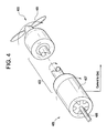
- a superconducting electrical generator system 400 is shown including a blade assembly 401 (a prime mover) mechanically linked to a mechanical linkage 403.
- a superconducting electrical generator 405 including an armature assembly 407 similar to the armature assembly 101 mechanically linked to the mechanical linkage 403, and a field assembly 409.
- the blade assembly 401 is rotated by wind power.
- the mechanical linkage 403 is rotated, and in turn, rotates the armature assembly 407.
- the field assembly 409 remains stationary.
- the interaction of flux in the superconducting electrical generator 405, and the rotation of the armature assembly 407 generates electrical current that may be sent to, for example, a power grid.
- the prime mover in FIG. 4 includes wind blades, the prime mover may be any other type of device, such as, for example, an engine that is operative to output mechanical energy.
- FIG. 5 illustrates an embodiment of an electrical generator system 500 that is similar to the superconducting electrical generator system 400 (of FIG. 4 ).
- the superconducting electrical generator system 500 is shown including a blade assembly 501 (a prime mover), mechanically linked to a mechanical linkage 503.
- a field assembly 509 of a superconducting electrical generator 505 is mechanically linked to the mechanical linkage 503.
- the superconducting electrical generator 505 includes an armature assembly 507.
- the stator assembly 507 remains stationary in operation, while the field assembly 509 is rotated by mechanical energy received from the blade assembly 501 via the mechanical linkage 503.
- the superconducting electrical generator outputs electrical current similarly to the current generation of the superconducting electrical generator system 400 (of FIG. 4 ).
- FIG. 6 illustrates a perspective partially cut-away view of an exemplary embodiment of a superconducting electrical motor system 600.
- the superconducting electrical motor system 600 includes a superconducting motor 605 including an armature assembly 607 that is similar to the armature assembly 101 described above, and a field assembly 609.
- the armature assembly 607 is mechanically linked to a mechanical linkage 603.
- the superconducting motor 605 receives current from a power source, such as, for example, a generator (not shown).
- the current induces a flux in the superconducting motor 605 that is operative to rotate the armature assembly 607.
- the mechanical linkage 630 rotates, and may be connected to, for example, a shaft 611.
- FIG. 7 illustrates a perspective partially cut-away view of an exemplary embodiment of a superconducting electrical motor system 700.
- the superconducting electrical motor system 700 includes a superconducting motor 705 that includes an armature assembly 707 and a field assembly 709.
- the armature assembly 707 is similar to the armature assembly 101 described above.
- the superconducting motor 705 receives current from a power source that induces a flux in the superconducting motor 705.
- the field assembly 709 rotates, and in turn, rotates the mechanical linkage 703.
- the mechanical linkage may be operative to rotate, for example, a shaft 711.
- the embodiments illustrated above may most effectively operate at low speeds (i.e. the relative speed between the rotors and armatures) of as low as approximately 10-25 revolutions per minute.
- An advantage of operating at low speeds is that the AC losses of the oversaturated magnetic portions of the armatures, e.g. the teeth, are lessened, resulting in a minimal loss of efficiency.
- the loss of mechanical output due to wasted AC current is also minimized.
Landscapes
- Engineering & Computer Science (AREA)
- Power Engineering (AREA)
- Life Sciences & Earth Sciences (AREA)
- Sustainable Development (AREA)
- Sustainable Energy (AREA)
- Chemical & Material Sciences (AREA)
- Combustion & Propulsion (AREA)
- Mechanical Engineering (AREA)
- General Engineering & Computer Science (AREA)
- Superconductive Dynamoelectric Machines (AREA)
Abstract
Description
- The described embodiments relate generally to superconducting generators and motors, and more particularly to systems involving generator and motor armatures with superconducting field windings.
- The superconducting field windings in superconducting motors and generators generate high magnetic fields in excess of the magnetic saturation of the magnetic teeth usually present in a stator. Superconducting motors and generators use complex assemblies of armature coils, cooling features, and nonmagnetic teeth between bars in the armatures to avoid losses in the saturated teeth. The use of these features adds cost for materials and assembly of the generators and motors.
- An exemplary embodiment according to one aspect of the present invention includes a system for generating power comprising, a superconducting generator including, an armature assembly comprising, a body portion, a tooth portion having a front surface and a rear surface, a slot partially defined by the body portion and the tooth portion, an armature bar engaging the slot, and a cooling cavity partially defined by the tooth portion, communicative with the front surface and the rear surface.
- An alternate exemplary embodiment according to an aspect of the present invention includes an electrical motor system comprising, a superconducting motor including, an armature assembly comprising, a body portion, a tooth portion having a front surface and a rear surface, a slot partially defined by the body portion and the tooth portion, an armature bar engaging the slot, and a cooling cavity partially defined by the tooth portion, communicative with the front surface and the rear surface.
- Another alternate exemplary embodiment includes an armature assembly of an electrical apparatus comprising, a body portion, a tooth portion having a front surface and a rear surface, a slot partially defined by the body portion and the tooth portion, an armature bar engaging the slot, a slot wedge member operative to engage the slot, and a cooling cavity partially defined by the tooth portion, communicative with the front surface and the rear surface.
- Various features, aspects, and advantages of the present invention will become better understood when the following detailed description is read with reference to the accompanying drawings in which like characters represent like parts throughout the drawings, wherein:
-
FIG. 1 illustrates a perspective partially cut-away view of an exemplary embodiment of an electrical device. -
FIG. 2 illustrates a side partially cut away view of an armature assembly of the electrical device ofFIG. 1 . -
FIG. 3 illustrates a side partially cut away view of an alternate embodiment of an armature assembly of the electrical device ofFIG. 1 . -
FIG. 4 illustrates a perspective view of an exemplary embodiment of a superconducting electrical generator system. -
FIG. 5 illustrates a perspective view of an alternate exemplary embodiment of a superconducting electrical generator system. -
FIG. 6 illustrates a perspective view of an exemplary embodiment of a superconducting electrical motor system. -
FIG. 7 illustrates a perspective view of an alternate exemplary embodiment of a superconducting electrical motor system. - In the following detailed description, numerous specific details are set forth in order to provide a thorough understanding of various embodiments. However, the embodiments may be practiced without these specific details. In other instances, well known methods, procedures, and components have not been described in detail.
- Further, various operations may be described as multiple discrete steps performed in a manner that is helpful for understanding the embodiments. However, the order of description should not be construed as to imply that these operations need be performed in the order they are presented, or that they are even order dependent. Moreover, repeated usage of the phrase "in an embodiment" does not necessarily refer to the same embodiment, although it may. Lastly, the terms "comprising," "including," "having," and the like, as used in the present application, are intended to be synonymous unless otherwise indicated.
- Motor and generator systems that use superconducting field windings may use complex assemblies of armature coils, cooling systems, and nonmagnetic teeth disposed between bars in the armature. Generator and motor systems experience losses from alternating current (AC) current in the armature; this occurs through eddy currents induced in the metals and magnetic hysteresis in the magnetic components, and these losses increase as AC frequency increases. The superconducting field windings often produce magnetic fields in excess of the saturation value of the magnetic teeth, and this, coupled with the AC effects, results in high losses. Nonmagnetic teeth or removal of the teeth can be used to reduce the losses, but this may result in a complex fabrication methods.
- It is desirable for an electrical system to have a less expensive armature assembly that is easier to manufacture and is capable of operating with a highly magnetically saturated armature teeth assembly with minimal AC current losses. This can be accomplished by constructing the teeth of the same metal (e.g., commonly, silicon iron) as and as extensions of the main magnetic body. Since in saturation the teeth no longer serve a magnetic function, the teeth may be designed and constructed for optimal structural and thermal performance.
-
FIG. 1 illustrates a perspective partially cut-away view of anelectrical device 100 having a superconducting field winding. Theelectrical device 100 is configured as a generator. However, a similar device may be configured as an electrical motor. Theelectrical device 100 includes anarmature portion 105 that includes anarmature assembly 101. The armature assembly contacts ayoke portion 103. Theelectrical device 100 also includes afield assembly 107 that comprises acryostat 109 with asuperconducting coil 111 inside the cryostat. - The
electrical device 100 is configured such that thearmature portion 105 rotates around thefield assembly 107. Other similar embodiments may be configured such that thearmature portion 105 is stationary and thefield assembly 107 rotates. The electrical device may receive mechanical energy from a prime mover (not shown) to generate electrical power. Alternatively, theelectrical device 100 may be configured as a motor that receives electrical power, and converts the electrical power to mechanical energy. -
FIG. 2 illustrates a side partially cut-away portion of an exemplary embodiment of thearmature assembly 101. Thearmature assembly 101 includes abody portion 201 that may, for example, be fabricated from laminated layers of metal. Teethportions 203 contact thebody portion 201 and may, for example, comprise of the same material as thebody portion 201, material such as, for example, laminated silicon-iron. Theteeth portions 203 may be an extension of the material that comprises thebody portion 201. Thebody portion 201 and theteeth portions 203 partially defineslots 205.Armature bars 207 engage theslots 205. Thearmature bars 207 may be electrically insulated byinsulator portions 209.FIG. 2 shows thefront surface 211 of theteeth portions 203.Cooling cavities 213 are partially defined by theteeth portions 203 and are communicative between thefront surface 211 and a rear surface 212 of the teeth portions 203 (not shown).Slot wedge members 215 may be included to engage theslots 205, and are operative to retain thearmature bars 207 in theslots 205. Thearmature bars 207 may comprise superconducting windings. In operation, thecooling cavities 213 transmit cooling air that is operative to cool thearmature assembly 101. -
FIG. 3 illustrates a side partially cut-away portion of an alternate exemplary embodiment of thearmature assembly 101. In the illustrated embodiment, thecooling cavities 213 are engaged withtube members 317 that are operative to receive a liquid coolant. In operation, the liquid coolant flowing through thetube members 317 cools thearmature assembly 101. The embodiments illustrated inFIGs. 2 and3 show nonlimiting examples ofcooling cavities 213. Other embodiments may include more or less numbers ofcooling cavities 213. -
FIGs. 4-7 illustrate embodiments of systems having armature assemblies similar to thearmature assembly 101. Referring toFIG. 4 , a superconductingelectrical generator system 400 is shown including a blade assembly 401 (a prime mover) mechanically linked to amechanical linkage 403. A superconductingelectrical generator 405 including anarmature assembly 407 similar to thearmature assembly 101 mechanically linked to themechanical linkage 403, and afield assembly 409. In operation, theblade assembly 401 is rotated by wind power. Themechanical linkage 403 is rotated, and in turn, rotates thearmature assembly 407. Thefield assembly 409 remains stationary. The interaction of flux in the superconductingelectrical generator 405, and the rotation of thearmature assembly 407 generates electrical current that may be sent to, for example, a power grid. Though the prime mover inFIG. 4 includes wind blades, the prime mover may be any other type of device, such as, for example, an engine that is operative to output mechanical energy. -
FIG. 5 illustrates an embodiment of anelectrical generator system 500 that is similar to the superconducting electrical generator system 400 (ofFIG. 4 ). The superconductingelectrical generator system 500 is shown including a blade assembly 501 (a prime mover), mechanically linked to amechanical linkage 503. Afield assembly 509 of a superconductingelectrical generator 505 is mechanically linked to themechanical linkage 503. The superconductingelectrical generator 505 includes anarmature assembly 507. In the illustrated embodiment, thestator assembly 507 remains stationary in operation, while thefield assembly 509 is rotated by mechanical energy received from theblade assembly 501 via themechanical linkage 503. The superconducting electrical generator outputs electrical current similarly to the current generation of the superconducting electrical generator system 400 (ofFIG. 4 ). -
FIG. 6 illustrates a perspective partially cut-away view of an exemplary embodiment of a superconductingelectrical motor system 600. The superconductingelectrical motor system 600 includes asuperconducting motor 605 including anarmature assembly 607 that is similar to thearmature assembly 101 described above, and afield assembly 609. Thearmature assembly 607 is mechanically linked to amechanical linkage 603. In operation, thesuperconducting motor 605 receives current from a power source, such as, for example, a generator (not shown). The current induces a flux in thesuperconducting motor 605 that is operative to rotate thearmature assembly 607. The mechanical linkage 630 rotates, and may be connected to, for example, ashaft 611. -
FIG. 7 illustrates a perspective partially cut-away view of an exemplary embodiment of a superconductingelectrical motor system 700. The superconductingelectrical motor system 700 includes asuperconducting motor 705 that includes anarmature assembly 707 and afield assembly 709. Thearmature assembly 707 is similar to thearmature assembly 101 described above. In operation, thesuperconducting motor 705 receives current from a power source that induces a flux in thesuperconducting motor 705. Thefield assembly 709 rotates, and in turn, rotates themechanical linkage 703. The mechanical linkage may be operative to rotate, for example, ashaft 711. - The embodiments illustrated above may most effectively operate at low speeds (i.e. the relative speed between the rotors and armatures) of as low as approximately 10-25 revolutions per minute. An advantage of operating at low speeds is that the AC losses of the oversaturated magnetic portions of the armatures, e.g. the teeth, are lessened, resulting in a minimal loss of efficiency. Regarding motor embodiments, the loss of mechanical output due to wasted AC current is also minimized.
- This written description uses examples to disclose the embodiments, including the preferred mode, and also to enable practice of the embodiments, including making and using any devices or systems and performing any incorporated methods. The patentable scope of the embodiments is defined by the claims, and may include other examples. Such other examples are intended to be within the scope of the claims if they have structural elements that do not differ from the literal language of the claims, or if they include equivalent structural elements with insubstantial differences from the literal languages of the claims.
- Various aspects and embodiments of the present invention are now defined by the following numbered clauses:
- 1. A system for generating power comprising:
- a superconducting generator including:
- an armature assembly comprising:
- a body portion;
- a tooth portion having a front surface and a rear surface;
- a slot partially defined by the body portion and the tooth portion;
- an armature bar engaging the slot; and
- a cooling cavity partially defined by the tooth portion, communicative with the front surface and the rear surface.
- an armature assembly comprising:
- a superconducting generator including:
- 2. The system of clause 1, wherein the tooth portion is an extension of the body portion.
- 3. The system of any preceding clause, wherein the armature assembly further comprises an insulator portion disposed between the armature bar and the slot, operative to electrically insulate the armature bar.
- 4. The system of any preceding clause, wherein the system further comprises a prime mover mechanically linked to the armature assembly, operative to rotate the armature assembly.
- 5. The system of any preceding clause, wherein the prime mover rotated by wind power.
- 6. The system of any preceding clause, wherein the system further comprises:
- a field assembly; and
- a prime mover mechanically linked to the field assembly operative to rotate the field assembly.
- 7. The system of any preceding clause, wherein the prime mover is rotated by wind power.
- 8. The system of any preceding clause, wherein the cooling cavity is operative to receive air operative to cool the armature assembly.
- 9. The system of any preceding clause, further comprising tube members engaging the cooling cavity operative to carry a liquid coolant.
- 10. An electrical motor system comprising:
- a superconducting motor including:
- an armature assembly comprising:
- a body portion;
- a tooth portion having a front surface and a rear surface;
- a slot partially defined by the body portion and the tooth portion;
- an armature bar engaging the slot; and
- a cooling cavity partially defined by the tooth portion, communicative with the front surface and the rear surface.
- an armature assembly comprising:
- a superconducting motor including:
- 11. The system of clause 10, wherein the tooth portion is an extension of the body portion.
- 12. The system of clause 10 or 11, wherein the armature assembly further comprises an insulator portion disposed between the armature bar and the slot, operative to electrically insulate the armature bar.
- 13. The system of any of clauses 10 to 12, wherein the system further comprises a mechanical linkage mechanically linked to the armature assembly, operative to rotate with the armature assembly.
- 14. The system of any of clauses 10 to 13, wherein the system further comprises:
- a field assembly; and
- a mechanical linkage linked to the field assembly operative to rotate with the field assembly.
- 15. The system of any of clauses 10 to 14, wherein the cooling cavity is operative to receive air operative to cool the armature assembly.
- 16. The system of any of clauses 10 to 15, further comprising tube members engaging the cooling cavity operative to carry a liquid coolant.
- 17. A an armature assembly of an electrical apparatus comprising:
- a body portion;
- a tooth portion having a front surface and a rear surface;
- a slot partially defined by the body portion and the tooth portion;
- an armature bar engaging the slot;
- a slot wedge member operative to engage the slot; and
- a cooling cavity partially defined by the tooth portion, communicative with the front surface and the rear surface.
- 18. The system of clause 17, wherein the armature assembly further comprises an insulator portion disposed between the armature bar and the slot, operative to electrically insulate the armature bar.
- 19. The system of clause 17 or 18, wherein the tooth portion is an extension of the body portion.
- 20. The system of any of clauses 17 to 19, further comprising tube members engaging the cooling cavity operative to carry a liquid coolant.
Claims (10)
- A system for generating power comprising:a superconducting generator (100) including:an armature assembly (105) comprising:a body portion (201);a tooth portion (203) having a front surface (211) and a rear surface (212);a slot (205) partially defined by the body portion (201) and the tooth portion(203);an armature bar (207) engaging the slot(205); anda cooling cavity (213) partially defined by the tooth portion (203), communicative with the front surface (211) and the rear surface (212).
- The system of claim 1, wherein the tooth portion (203) is an extension of the body portion (201).
- The system of any preceding claim, wherein the system further comprises a prime mover (401) mechanically linked to the armature assembly (407), operative to rotate the armature assembly (407).
- The system of any preceding claim, wherein the system further comprises:a rotor assembly (409); anda prime mover (401) mechanically linked to the rotor assembly (409) operative to rotate the rotor assembly (409).
- The system of any preceding claim, further comprising tube members (317) engaging the cooling cavity (213) operative to carry a liquid coolant.
- An electrical motor system comprising:a superconducting motor (100) including:an armature assembly (105) comprising:a body portion (201);a tooth portion (203) having a front surface (211) and a rear surface (212);a slot (205) partially defined by the body portion (201) and the tooth portion(203);an armature bar (207) engaging the slot(205); anda cooling cavity (213) partially defined by the tooth portion (203), communicative with the front surface (211) and the rear surface (212).
- The system of claim 6, wherein the tooth portion (203) is an extension of the body portion (201).
- The system of claim 6 or 7, wherein the system further comprises a mechanical linkage (403) mechanically linked to the armature assembly (105), operative to rotate with the armature assembly (105).
- The system of any of claims 6 to 8, wherein the system further comprises:a rotor assembly (409); anda mechanical linkage (403) linked to the rotor assembly (409) operative to rotate with the rotor assembly (409).
- The system of any of claims 6 to 9, further comprising tube members (317) engaging the cooling cavity (213) operative to carry a liquid coolant.
Applications Claiming Priority (1)
| Application Number | Priority Date | Filing Date | Title |
|---|---|---|---|
| US12/123,061 US7928616B2 (en) | 2008-05-19 | 2008-05-19 | Systems and apparatus involving toothed armatures in superconducting machines |
Publications (3)
| Publication Number | Publication Date |
|---|---|
| EP2124322A2 true EP2124322A2 (en) | 2009-11-25 |
| EP2124322A3 EP2124322A3 (en) | 2011-12-28 |
| EP2124322B1 EP2124322B1 (en) | 2014-03-05 |
Family
ID=40757031
Family Applications (1)
| Application Number | Title | Priority Date | Filing Date |
|---|---|---|---|
| EP09159781.5A Not-in-force EP2124322B1 (en) | 2008-05-19 | 2009-05-08 | System and apparatus involving toothed armatures in superconducting machines |
Country Status (4)
| Country | Link |
|---|---|
| US (1) | US7928616B2 (en) |
| EP (1) | EP2124322B1 (en) |
| CN (1) | CN101588122B (en) |
| DK (1) | DK2124322T3 (en) |
Cited By (2)
| Publication number | Priority date | Publication date | Assignee | Title |
|---|---|---|---|---|
| EP2806537A2 (en) | 2013-05-22 | 2014-11-26 | Acciona Windpower S.a. | Rotary electric generator stator, rotary electric generator comprising said stator, and wind turbine incorporating said rotary electric generator |
| EP3079239A1 (en) * | 2015-04-09 | 2016-10-12 | GE Energy Power Conversion Technology Ltd | Stators for electrical machines |
Families Citing this family (8)
| Publication number | Priority date | Publication date | Assignee | Title |
|---|---|---|---|---|
| CN102299575A (en) * | 2011-08-23 | 2011-12-28 | 浙江泰达微电机有限公司 | Rotor sheet for fan motor |
| US20150207365A1 (en) * | 2013-12-05 | 2015-07-23 | General Electric Company | Superconducting power generation system and associated method for generating power |
| DE102016217734A1 (en) | 2016-09-16 | 2018-03-22 | Siemens Aktiengesellschaft | Rotor with coil arrangement and winding carrier |
| WO2020005221A1 (en) * | 2018-06-27 | 2020-01-02 | General Electric Company | Rotating armature for a wind turbine generator having a superconducting stator |
| EP3609060A1 (en) * | 2018-08-08 | 2020-02-12 | Siemens Gamesa Renewable Energy A/S | Generator having superconducting coil windings |
| US11387699B2 (en) | 2020-12-15 | 2022-07-12 | General Electric Renovables Espana, S.L. | Rotating cooling system for wind turbine generator |
| US12166399B2 (en) * | 2021-09-14 | 2024-12-10 | Hinetics LLC | External rotor aircraft motor having force isolated cantilevered rotor |
| CN114320755B (en) * | 2021-12-08 | 2024-05-24 | 武汉船用电力推进装置研究所(中国船舶重工集团公司第七一二研究所) | Direct-drive superconducting wind power generator |
Citations (2)
| Publication number | Priority date | Publication date | Assignee | Title |
|---|---|---|---|---|
| EP0684682A1 (en) | 1994-05-24 | 1995-11-29 | Gec Alsthom Limited | Improvements in or relating to cooling arrangements for rotating electrical machines |
| US7211919B2 (en) | 1999-08-16 | 2007-05-01 | American Superconductor Corporation | Thermally-conductive stator support structure |
Family Cites Families (13)
| Publication number | Priority date | Publication date | Assignee | Title |
|---|---|---|---|---|
| DE2511104C3 (en) * | 1975-03-13 | 1979-10-31 | Kraftwerk Union Ag, 4330 Muelheim | Cooling arrangement for a superconducting excitation winding |
| US6313556B1 (en) * | 1999-09-30 | 2001-11-06 | Reliance Electric Technologies, Llc | Superconducting electromechanical rotating device having a liquid-cooled, potted, one layer stator winding |
| US6683398B2 (en) * | 2000-12-01 | 2004-01-27 | General Electric Company | Generator magnetic armature wedge |
| JP3806303B2 (en) * | 2000-12-11 | 2006-08-09 | 三菱重工業株式会社 | Cooling structure in generator |
| WO2002063751A1 (en) * | 2000-12-29 | 2002-08-15 | General Electric Company | Superconductive armature winding for an electrical machine |
| JP2003056461A (en) * | 2001-02-15 | 2003-02-26 | Denso Corp | Combined drive system for compressor |
| US6819016B2 (en) * | 2002-07-18 | 2004-11-16 | Tm4 Inc. | Liquid cooling arrangement for electric machines |
| US7547999B2 (en) * | 2003-04-28 | 2009-06-16 | General Electric Company | Superconducting multi-pole electrical machine |
| US20040239201A1 (en) * | 2003-05-27 | 2004-12-02 | General Electric Company | Methods and apparatus for assembling homopolar inductor alternators including superconducting windings |
| US6965183B2 (en) * | 2003-05-27 | 2005-11-15 | Pratt & Whitney Canada Corp. | Architecture for electric machine |
| US6897577B2 (en) * | 2003-07-14 | 2005-05-24 | General Electric Company | Methods and system for power generation |
| US7463914B2 (en) * | 2005-06-08 | 2008-12-09 | Dynamo Capital, Inc. | Superconducting acyclic homopolar electromechanical power converter |
| US7821164B2 (en) * | 2007-02-15 | 2010-10-26 | General Electric Company | Method and apparatus for a superconducting generator driven by wind turbine |
-
2008
- 2008-05-19 US US12/123,061 patent/US7928616B2/en not_active Expired - Fee Related
-
2009
- 2009-05-08 DK DK09159781.5T patent/DK2124322T3/en active
- 2009-05-08 EP EP09159781.5A patent/EP2124322B1/en not_active Not-in-force
- 2009-05-18 CN CN2009101454119A patent/CN101588122B/en not_active Expired - Fee Related
Patent Citations (3)
| Publication number | Priority date | Publication date | Assignee | Title |
|---|---|---|---|---|
| EP0684682A1 (en) | 1994-05-24 | 1995-11-29 | Gec Alsthom Limited | Improvements in or relating to cooling arrangements for rotating electrical machines |
| US5866959A (en) | 1994-05-24 | 1999-02-02 | Gec Alsthom Limited | Cooling arrangements for rotating electrical machines |
| US7211919B2 (en) | 1999-08-16 | 2007-05-01 | American Superconductor Corporation | Thermally-conductive stator support structure |
Cited By (5)
| Publication number | Priority date | Publication date | Assignee | Title |
|---|---|---|---|---|
| EP2806537A2 (en) | 2013-05-22 | 2014-11-26 | Acciona Windpower S.a. | Rotary electric generator stator, rotary electric generator comprising said stator, and wind turbine incorporating said rotary electric generator |
| EP2806537A3 (en) * | 2013-05-22 | 2016-01-06 | Acciona Windpower S.a. | Rotary electric generator stator, rotary electric generator comprising said stator, and wind turbine incorporating said rotary electric generator |
| US10148154B2 (en) | 2013-05-22 | 2018-12-04 | Acciona Windpower, S.A. | Rotary electric generator stator, rotary electric generator comprising said stator and wind turbine incorporating said rotary electric generator |
| EP3079239A1 (en) * | 2015-04-09 | 2016-10-12 | GE Energy Power Conversion Technology Ltd | Stators for electrical machines |
| US10784745B2 (en) | 2015-04-09 | 2020-09-22 | Ge Energy Power Conversion Technology Ltd. | Stators for electrical machines |
Also Published As
| Publication number | Publication date |
|---|---|
| US20090284086A1 (en) | 2009-11-19 |
| EP2124322A3 (en) | 2011-12-28 |
| CN101588122B (en) | 2013-09-25 |
| EP2124322B1 (en) | 2014-03-05 |
| DK2124322T3 (en) | 2014-04-22 |
| US7928616B2 (en) | 2011-04-19 |
| CN101588122A (en) | 2009-11-25 |
Similar Documents
| Publication | Publication Date | Title |
|---|---|---|
| US7928616B2 (en) | Systems and apparatus involving toothed armatures in superconducting machines | |
| JP4311643B2 (en) | Method for manufacturing permanent magnet type rotating electric machine and method for manufacturing permanent magnet type synchronous generator for wind power generation | |
| US10666109B2 (en) | Stator coil, stator including said stator coil, and rotating electric machine including said stator | |
| Cros et al. | New structures of polyphase claw-pole machines | |
| Golovanov et al. | Designing an advanced electrical motor for propulsion of electric aircraft | |
| Dajaku et al. | Low costs and high efficiency asynchronous machine with stator cage winding | |
| EP2429063A1 (en) | Ac elelctric machine with claw poles | |
| US10411526B2 (en) | Stator for rotating electrical machine and rotating electrical machine | |
| CN110771013A (en) | Stator of rotating electric machine and rotating electric machine | |
| US20180248453A1 (en) | Rotor, Rotating Electric Machine Including Said Rotor, and Method of Manufacturing Said Rotor | |
| Xinghe et al. | Numerical analysis on the magnetic field of hybrid exciting synchronous generator | |
| EP2833526A1 (en) | Electrical power motor-generator excited by magnetic transference | |
| CN110771012A (en) | Stator of rotating electric machine and rotating electric machine | |
| Zhang et al. | High speed permanent magnet motor design and power loss analysis | |
| US10770956B2 (en) | Electric machine | |
| KR20210137550A (en) | Permanent Magnet Auxiliary Synchronous Reluctance Machine | |
| JP2002238194A (en) | Rotor structure of permanent magnet motor | |
| Karnavas et al. | An investigation study considering the effect of magnet type, slot type and pole-arc to pole-pitch ratio variation on PM brushless DC motor design | |
| CN101282050A (en) | A slotless stator of an evaporative cooling motor | |
| JP2010516224A (en) | Multi-phase drive or generator machine | |
| Mantione et al. | Evaluation of different magnet materials and skewed geometries for ipmsm at high speed | |
| KR20000029130A (en) | A magnet type motor and generator | |
| Oosthuizen et al. | Design of an Ironless Double-Rotor Radial Flux Permanent Magnet Machine | |
| Sarumol et al. | Minimisation of losses in permanent magnet synchronous generator for high speed applications | |
| Jibin et al. | Influence of the axial-length ratio of permanent magnet to homopolar induction on the performance of hybrid excitation synchronous generator |
Legal Events
| Date | Code | Title | Description |
|---|---|---|---|
| PUAI | Public reference made under article 153(3) epc to a published international application that has entered the european phase |
Free format text: ORIGINAL CODE: 0009012 |
|
| AK | Designated contracting states |
Kind code of ref document: A2 Designated state(s): AT BE BG CH CY CZ DE DK EE ES FI FR GB GR HR HU IE IS IT LI LT LU LV MC MK MT NL NO PL PT RO SE SI SK TR |
|
| PUAL | Search report despatched |
Free format text: ORIGINAL CODE: 0009013 |
|
| AK | Designated contracting states |
Kind code of ref document: A3 Designated state(s): AT BE BG CH CY CZ DE DK EE ES FI FR GB GR HR HU IE IS IT LI LT LU LV MC MK MT NL NO PL PT RO SE SI SK TR |
|
| AX | Request for extension of the european patent |
Extension state: AL BA RS |
|
| RIC1 | Information provided on ipc code assigned before grant |
Ipc: H02K 55/00 20060101AFI20111124BHEP |
|
| 17P | Request for examination filed |
Effective date: 20120628 |
|
| 17Q | First examination report despatched |
Effective date: 20120803 |
|
| REG | Reference to a national code |
Ref country code: DE Ref legal event code: R079 Ref document number: 602009022128 Country of ref document: DE Free format text: PREVIOUS MAIN CLASS: H02K0055000000 Ipc: H02K0055060000 |
|
| GRAP | Despatch of communication of intention to grant a patent |
Free format text: ORIGINAL CODE: EPIDOSNIGR1 |
|
| RIC1 | Information provided on ipc code assigned before grant |
Ipc: H02K 7/18 20060101ALI20130918BHEP Ipc: H02K 55/06 20060101AFI20130918BHEP Ipc: H02K 1/20 20060101ALI20130918BHEP |
|
| INTG | Intention to grant announced |
Effective date: 20131009 |
|
| GRAS | Grant fee paid |
Free format text: ORIGINAL CODE: EPIDOSNIGR3 |
|
| GRAA | (expected) grant |
Free format text: ORIGINAL CODE: 0009210 |
|
| AK | Designated contracting states |
Kind code of ref document: B1 Designated state(s): AT BE BG CH CY CZ DE DK EE ES FI FR GB GR HR HU IE IS IT LI LT LU LV MC MK MT NL NO PL PT RO SE SI SK TR |
|
| REG | Reference to a national code |
Ref country code: GB Ref legal event code: FG4D |
|
| REG | Reference to a national code |
Ref country code: CH Ref legal event code: EP |
|
| REG | Reference to a national code |
Ref country code: AT Ref legal event code: REF Ref document number: 655446 Country of ref document: AT Kind code of ref document: T Effective date: 20140315 |
|
| REG | Reference to a national code |
Ref country code: IE Ref legal event code: FG4D |
|
| REG | Reference to a national code |
Ref country code: DE Ref legal event code: R096 Ref document number: 602009022128 Country of ref document: DE Effective date: 20140417 |
|
| REG | Reference to a national code |
Ref country code: DK Ref legal event code: T3 Effective date: 20140411 |
|
| REG | Reference to a national code |
Ref country code: AT Ref legal event code: MK05 Ref document number: 655446 Country of ref document: AT Kind code of ref document: T Effective date: 20140305 |
|
| REG | Reference to a national code |
Ref country code: NL Ref legal event code: VDEP Effective date: 20140305 |
|
| PG25 | Lapsed in a contracting state [announced via postgrant information from national office to epo] |
Ref country code: NO Free format text: LAPSE BECAUSE OF FAILURE TO SUBMIT A TRANSLATION OF THE DESCRIPTION OR TO PAY THE FEE WITHIN THE PRESCRIBED TIME-LIMIT Effective date: 20140605 Ref country code: LT Free format text: LAPSE BECAUSE OF FAILURE TO SUBMIT A TRANSLATION OF THE DESCRIPTION OR TO PAY THE FEE WITHIN THE PRESCRIBED TIME-LIMIT Effective date: 20140305 |
|
| REG | Reference to a national code |
Ref country code: LT Ref legal event code: MG4D |
|
| PG25 | Lapsed in a contracting state [announced via postgrant information from national office to epo] |
Ref country code: AT Free format text: LAPSE BECAUSE OF FAILURE TO SUBMIT A TRANSLATION OF THE DESCRIPTION OR TO PAY THE FEE WITHIN THE PRESCRIBED TIME-LIMIT Effective date: 20140305 Ref country code: SE Free format text: LAPSE BECAUSE OF FAILURE TO SUBMIT A TRANSLATION OF THE DESCRIPTION OR TO PAY THE FEE WITHIN THE PRESCRIBED TIME-LIMIT Effective date: 20140305 Ref country code: FI Free format text: LAPSE BECAUSE OF FAILURE TO SUBMIT A TRANSLATION OF THE DESCRIPTION OR TO PAY THE FEE WITHIN THE PRESCRIBED TIME-LIMIT Effective date: 20140305 Ref country code: CY Free format text: LAPSE BECAUSE OF FAILURE TO SUBMIT A TRANSLATION OF THE DESCRIPTION OR TO PAY THE FEE WITHIN THE PRESCRIBED TIME-LIMIT Effective date: 20140305 |
|
| PG25 | Lapsed in a contracting state [announced via postgrant information from national office to epo] |
Ref country code: LV Free format text: LAPSE BECAUSE OF FAILURE TO SUBMIT A TRANSLATION OF THE DESCRIPTION OR TO PAY THE FEE WITHIN THE PRESCRIBED TIME-LIMIT Effective date: 20140305 Ref country code: HR Free format text: LAPSE BECAUSE OF FAILURE TO SUBMIT A TRANSLATION OF THE DESCRIPTION OR TO PAY THE FEE WITHIN THE PRESCRIBED TIME-LIMIT Effective date: 20140305 |
|
| PG25 | Lapsed in a contracting state [announced via postgrant information from national office to epo] |
Ref country code: BE Free format text: LAPSE BECAUSE OF FAILURE TO SUBMIT A TRANSLATION OF THE DESCRIPTION OR TO PAY THE FEE WITHIN THE PRESCRIBED TIME-LIMIT Effective date: 20140305 Ref country code: IS Free format text: LAPSE BECAUSE OF FAILURE TO SUBMIT A TRANSLATION OF THE DESCRIPTION OR TO PAY THE FEE WITHIN THE PRESCRIBED TIME-LIMIT Effective date: 20140705 Ref country code: RO Free format text: LAPSE BECAUSE OF FAILURE TO SUBMIT A TRANSLATION OF THE DESCRIPTION OR TO PAY THE FEE WITHIN THE PRESCRIBED TIME-LIMIT Effective date: 20140305 Ref country code: BG Free format text: LAPSE BECAUSE OF FAILURE TO SUBMIT A TRANSLATION OF THE DESCRIPTION OR TO PAY THE FEE WITHIN THE PRESCRIBED TIME-LIMIT Effective date: 20140605 Ref country code: EE Free format text: LAPSE BECAUSE OF FAILURE TO SUBMIT A TRANSLATION OF THE DESCRIPTION OR TO PAY THE FEE WITHIN THE PRESCRIBED TIME-LIMIT Effective date: 20140305 Ref country code: NL Free format text: LAPSE BECAUSE OF FAILURE TO SUBMIT A TRANSLATION OF THE DESCRIPTION OR TO PAY THE FEE WITHIN THE PRESCRIBED TIME-LIMIT Effective date: 20140305 Ref country code: CZ Free format text: LAPSE BECAUSE OF FAILURE TO SUBMIT A TRANSLATION OF THE DESCRIPTION OR TO PAY THE FEE WITHIN THE PRESCRIBED TIME-LIMIT Effective date: 20140305 |
|
| PG25 | Lapsed in a contracting state [announced via postgrant information from national office to epo] |
Ref country code: ES Free format text: LAPSE BECAUSE OF FAILURE TO SUBMIT A TRANSLATION OF THE DESCRIPTION OR TO PAY THE FEE WITHIN THE PRESCRIBED TIME-LIMIT Effective date: 20140305 Ref country code: PL Free format text: LAPSE BECAUSE OF FAILURE TO SUBMIT A TRANSLATION OF THE DESCRIPTION OR TO PAY THE FEE WITHIN THE PRESCRIBED TIME-LIMIT Effective date: 20140305 Ref country code: SK Free format text: LAPSE BECAUSE OF FAILURE TO SUBMIT A TRANSLATION OF THE DESCRIPTION OR TO PAY THE FEE WITHIN THE PRESCRIBED TIME-LIMIT Effective date: 20140305 |
|
| REG | Reference to a national code |
Ref country code: DE Ref legal event code: R097 Ref document number: 602009022128 Country of ref document: DE |
|
| PG25 | Lapsed in a contracting state [announced via postgrant information from national office to epo] |
Ref country code: PT Free format text: LAPSE BECAUSE OF FAILURE TO SUBMIT A TRANSLATION OF THE DESCRIPTION OR TO PAY THE FEE WITHIN THE PRESCRIBED TIME-LIMIT Effective date: 20140707 Ref country code: LU Free format text: LAPSE BECAUSE OF FAILURE TO SUBMIT A TRANSLATION OF THE DESCRIPTION OR TO PAY THE FEE WITHIN THE PRESCRIBED TIME-LIMIT Effective date: 20140508 |
|
| REG | Reference to a national code |
Ref country code: CH Ref legal event code: PL |
|
| PLBE | No opposition filed within time limit |
Free format text: ORIGINAL CODE: 0009261 |
|
| STAA | Information on the status of an ep patent application or granted ep patent |
Free format text: STATUS: NO OPPOSITION FILED WITHIN TIME LIMIT |
|
| PG25 | Lapsed in a contracting state [announced via postgrant information from national office to epo] |
Ref country code: LI Free format text: LAPSE BECAUSE OF NON-PAYMENT OF DUE FEES Effective date: 20140531 Ref country code: MC Free format text: LAPSE BECAUSE OF FAILURE TO SUBMIT A TRANSLATION OF THE DESCRIPTION OR TO PAY THE FEE WITHIN THE PRESCRIBED TIME-LIMIT Effective date: 20140305 Ref country code: CH Free format text: LAPSE BECAUSE OF NON-PAYMENT OF DUE FEES Effective date: 20140531 |
|
| 26N | No opposition filed |
Effective date: 20141208 |
|
| GBPC | Gb: european patent ceased through non-payment of renewal fee |
Effective date: 20140605 |
|
| REG | Reference to a national code |
Ref country code: IE Ref legal event code: MM4A |
|
| REG | Reference to a national code |
Ref country code: FR Ref legal event code: ST Effective date: 20150130 |
|
| REG | Reference to a national code |
Ref country code: DE Ref legal event code: R097 Ref document number: 602009022128 Country of ref document: DE Effective date: 20141208 |
|
| PG25 | Lapsed in a contracting state [announced via postgrant information from national office to epo] |
Ref country code: IT Free format text: LAPSE BECAUSE OF FAILURE TO SUBMIT A TRANSLATION OF THE DESCRIPTION OR TO PAY THE FEE WITHIN THE PRESCRIBED TIME-LIMIT Effective date: 20140305 |
|
| PG25 | Lapsed in a contracting state [announced via postgrant information from national office to epo] |
Ref country code: IE Free format text: LAPSE BECAUSE OF NON-PAYMENT OF DUE FEES Effective date: 20140508 |
|
| PG25 | Lapsed in a contracting state [announced via postgrant information from national office to epo] |
Ref country code: SI Free format text: LAPSE BECAUSE OF FAILURE TO SUBMIT A TRANSLATION OF THE DESCRIPTION OR TO PAY THE FEE WITHIN THE PRESCRIBED TIME-LIMIT Effective date: 20140305 Ref country code: GB Free format text: LAPSE BECAUSE OF NON-PAYMENT OF DUE FEES Effective date: 20140605 Ref country code: FR Free format text: LAPSE BECAUSE OF NON-PAYMENT OF DUE FEES Effective date: 20140602 |
|
| PG25 | Lapsed in a contracting state [announced via postgrant information from national office to epo] |
Ref country code: MT Free format text: LAPSE BECAUSE OF FAILURE TO SUBMIT A TRANSLATION OF THE DESCRIPTION OR TO PAY THE FEE WITHIN THE PRESCRIBED TIME-LIMIT Effective date: 20140305 |
|
| PG25 | Lapsed in a contracting state [announced via postgrant information from national office to epo] |
Ref country code: GR Free format text: LAPSE BECAUSE OF FAILURE TO SUBMIT A TRANSLATION OF THE DESCRIPTION OR TO PAY THE FEE WITHIN THE PRESCRIBED TIME-LIMIT Effective date: 20140606 |
|
| PG25 | Lapsed in a contracting state [announced via postgrant information from national office to epo] |
Ref country code: TR Free format text: LAPSE BECAUSE OF FAILURE TO SUBMIT A TRANSLATION OF THE DESCRIPTION OR TO PAY THE FEE WITHIN THE PRESCRIBED TIME-LIMIT Effective date: 20140305 Ref country code: HU Free format text: LAPSE BECAUSE OF FAILURE TO SUBMIT A TRANSLATION OF THE DESCRIPTION OR TO PAY THE FEE WITHIN THE PRESCRIBED TIME-LIMIT; INVALID AB INITIO Effective date: 20090508 |
|
| PG25 | Lapsed in a contracting state [announced via postgrant information from national office to epo] |
Ref country code: MK Free format text: LAPSE BECAUSE OF FAILURE TO SUBMIT A TRANSLATION OF THE DESCRIPTION OR TO PAY THE FEE WITHIN THE PRESCRIBED TIME-LIMIT Effective date: 20140305 |
|
| PGFP | Annual fee paid to national office [announced via postgrant information from national office to epo] |
Ref country code: DK Payment date: 20180525 Year of fee payment: 10 Ref country code: DE Payment date: 20180529 Year of fee payment: 10 |
|
| REG | Reference to a national code |
Ref country code: DE Ref legal event code: R119 Ref document number: 602009022128 Country of ref document: DE |
|
| REG | Reference to a national code |
Ref country code: DK Ref legal event code: EBP Effective date: 20190531 |
|
| PG25 | Lapsed in a contracting state [announced via postgrant information from national office to epo] |
Ref country code: DK Free format text: LAPSE BECAUSE OF NON-PAYMENT OF DUE FEES Effective date: 20190531 Ref country code: DE Free format text: LAPSE BECAUSE OF NON-PAYMENT OF DUE FEES Effective date: 20191203 |