EP2124812B1 - Medizinisches, insbesondere dentalmedizinisches, handstück mit zwei voneinander getrennten austrittsöffnungen für medien - Google Patents
Medizinisches, insbesondere dentalmedizinisches, handstück mit zwei voneinander getrennten austrittsöffnungen für medien Download PDFInfo
- Publication number
- EP2124812B1 EP2124812B1 EP08715740.0A EP08715740A EP2124812B1 EP 2124812 B1 EP2124812 B1 EP 2124812B1 EP 08715740 A EP08715740 A EP 08715740A EP 2124812 B1 EP2124812 B1 EP 2124812B1
- Authority
- EP
- European Patent Office
- Prior art keywords
- handpiece
- light guide
- lines
- media
- cannula
- Prior art date
- Legal status (The legal status is an assumption and is not a legal conclusion. Google has not performed a legal analysis and makes no representation as to the accuracy of the status listed.)
- Active
Links
Images

Classifications
-
- A—HUMAN NECESSITIES
- A61—MEDICAL OR VETERINARY SCIENCE; HYGIENE
- A61C—DENTISTRY; APPARATUS OR METHODS FOR ORAL OR DENTAL HYGIENE
- A61C17/00—Devices for cleaning, polishing, rinsing or drying teeth, teeth cavities or prostheses; Saliva removers; Dental appliances for receiving spittle
- A61C17/02—Rinsing or air-blowing devices, e.g. using fluid jets or comprising liquid medication
- A61C17/0202—Hand-pieces
Definitions
- the invention relates to a medical, in particular dental medical, handpiece according to claim 1.
- medical or dental handpieces one differentiates between those who are equipped with a tool for the treatment of the human or animal body or be equipped and with which mechanically on the human or animal body or acting on a model, and such handpieces serving to maintain the treatment site of the human or animal body in operative condition, and delivering, for example, water and / or air for cooling and cleaning the treatment site, or delivering light to the treatment site , or draining body fluid, eg, saliva or blood, from the treatment site or probing the treatment site.
- the first type handpieces with working handpieces and the second type is referred to with functional handpieces.
- a functional handpiece can thus be a rinsing and / or blowing or suction handpiece or cannula handpiece or a lighting handpiece or a probe handpiece.
- a dental handpiece according to the species specified in the preamble of claim 1 or 3 is as a functional handpiece in the form of a flushing and Blashand foundeds or cannula handpiece in the US 2005/0048436 A1 described and thus previously known.
- This handpiece serves to supply water and / or air or light to the treatment site. It has an elongated handle portion, with the front end of a cannula is detachably connected, which consists of translucent material, so that it serves as a light guide and emits the light at the front end of the cannula.
- a media conduit for air and a fluid conduit for water extend longitudinally through the solid material of the cannula, emerging from the cannula at spaced outlet openings.
- the respective desired medium water or air and an associated light source can be selectively switched on and off by the manual operation of an actuator.
- a generic dental handpiece which is designed as a working handpiece and has a so-called drive sleeve, which is rotatable by a drive motor and has an accessible from one side insertion opening for a tool.
- This previously known work handpiece has, in a distance directed rearwardly from the insertion opening, an exit zone in which two media lines and a light guide open, the axes of the exit openings of the media lines and the exit surface of the light guide being directed obliquely onto the free end region of an inserted tool.
- a medical, especially dental medical, handpiece is used in most cases of use at small treatment sites, eg. B. in body cavities, such as in a mouth of a patient. It is therefore required a small construction, on the one hand to achieve the treatment or job space and on the other to affect the visual view of the treatment or job as little as possible. This results in the media outlet openings difficult constructions. It is from one in the DE 35 00 085 C2 described handpiece known to mix the escaping air and the escaping water in the region of a common outlet opening to a spray, wherein only spray exits the outlet opening. It is also desirable that the light emitted by the light guide light should be directed low and preferably without shadowing on the treatment or job.
- a dental handpiece is known in which a water pipe and an air pipe extend forward. The lines are aligned so that the discharged media meet at a distance in front of the outlet openings.
- a comparable spray handpiece is also from the Scriptures DE 37 34 862 A1 known.
- the invention has for its object to improve in a handpiece according to the preamble of claim 1, the media delivery. It should be a simple, small and preferably inexpensive to produce construction be possible. This object is solved by the features of claim 1.
- Advantageous developments of the invention are described in the appended subclaims.
- the invention is based on the finding that, on the one hand, a construction which causes a spray discharge in the region of the outlet opening is complicated and expensive, and, on the other hand, it is advantageous for reasons of different treatment requirements to have a water jet and a spray jet available.
- the media lines are aligned so that the discharged media meet at a certain distance in front of the exit zone to produce a spray.
- the media leave the outlet openings initially separated from each other, for. B. as water and air, wherein only at a distance in front of the outlet openings, the spray is done automatically by a meeting of the flow jets.
- the treatment person has different media compositions available during treatment, e.g. As water, air or spray, which can be exploited by the fact that the handpiece is used in its use at different distances from the treatment site.
- media compositions available during treatment, e.g. As water, air or spray, which can be exploited by the fact that the handpiece is used in its use at different distances from the treatment site.
- the effectiveness of the one medium e.g. As water
- a spray flow can be used at a greater distance from the outlet openings. Incidentally, a spray of advantageous composition is produced.
- the optical waveguide has in its front longitudinal region at least two longitudinal grooves into which the media conduits formed by hollow conduits are arranged to be radially insertable from the outside to the inside.
- the accessibility of the longitudinal grooves from the outside not only enables a simple and cost-effective production, but also the media lines can be inserted and positioned therein simply and quickly, eg. B. with a surrounding the light guide and the media lines sleeve, which may be an inner sleeve.
- the sleeve is preferably surrounded by an outer sleeve forming the cannula. Such a sleeve facilitates and improves the prefabrication of a unit comprising the media lines, the light guide and the sleeve.
- the media lines 3, 4 extend in the handpiece body 2 from the rear end portion to the front end portion, wherein they open at outlet openings, which are directed to the acting with the handpiece 1 surgical site to perform in their area a blowing function, a rinsing function or a cooling function ,
- the light emitting surface 5a is also directed to the treatment site to illuminate it.
- the outlet openings 3a, 4a of the media lines 3, 4 and the light emitting surface 5a of the illumination device 5 are located on the front side of a cannula 6 forming the front end region of the handpiece body 2 is releasably connected by a releasable coupling device 7 in the form of a quick-release connection with the front end of a likewise elongate extending handle portion 8, which forms the rear portion of the handpiece body 2.
- the cannula 6 can also be connected inseparably or integrally with the grip part 8.
- the cannula 6 extends curved toward one side of the handpiece body 2, making it particularly suitable for dental treatment in the oral cavity of a patient.
- the cannula 6 can also extend in a different shape and direction, for. B. straight.
- the coupling device 7 is preferably an automatically latching plug-in coupling, in particular a plug-in / rotary coupling known per se with a coupling recess 7a on one part and a plug-in and rotatable coupling pin 7b on the other part, wherein preferably the coupling pin 7b of the cannula 6 to the rear protrudes and the coupling recess 7a is disposed in the front end portion of the handle portion 8 and opens to the front.
- Fig. 3 For locking the cannula 6 in the coupled state, one or more in Fig. 3 illustrated locking lugs 9a of a latching device 9, z. B. in the form of spring tongues 9b, in particular in the rear end region of the cannula 6, which engage on not shown counter-locking elements of the handle part 8.
- the lighting device 5 preferably has a light guide 11 which is arranged in the handpiece body 2 and upstream of a light source, not shown, and extends forward to an exit surface 12, which is preferably a flat surface and in the embodiment of a handpiece 1 with a cannula 6 the End face of the cannula 6 forms.
- an exit surface 12 which is preferably a flat surface and in the embodiment of a handpiece 1 with a cannula 6 the End face of the cannula 6 forms.
- the rear end of the light guide 11 in the rear end of the cannula 6 and the light source in the handle part 8 are arranged.
- the main parts of the cannula 6 are a base part 13, which, e.g. forms a Kanegaenfuß with the rearwardly projecting from him coupling pin 7b, preferably laterally curved and z.
- the hollow lines 3b, 4b also extend through the through hole 17 in the inner sleeve 18, which forms a common through hole 17 for the optical waveguide 11 and the hollow lines 3b, 4b.
- the rear-side connection of the hollow conduits 3b, 4b with the longitudinal channels 3c, 4c can be effected by plug-in connections 3d, 4d, in which the hollow conduits 3b, 4b are mounted on or in corresponding connecting elements.
- the hollow pipes 3b, 4b may be tubes or hoses, the z. B. may consist of metal or plastic.
- the light guide 11 has in the region of the base part 13 has a circular cross-section, and it is inserted and sealed with little play in the through hole 15 with a corresponding circular cross-section from the front, z.
- the optical waveguide 11 changes its cross-sectional shape such that it is in its front End portion in the one transverse direction q1 has an increased width a and in the other transversely directed thereto transverse direction q2 has a width b which is smaller than the enlarged width a.
- the optical waveguide 11 extends in this end region denoted by 11a with a waisted web section 11b between the waveguides 3b, 4b, so that they are located on the broad sides of the optical waveguide 11.
- the enlarged width a is greater than the preferably circular cross-sectional size c of the waveguides 3b, 4b, wherein the one waveguide 3b, in particular for air, a larger cross-sectional size c than the other waveguide 4b may have.
- the optical waveguide 11 preferably has substantially centrally arranged longitudinal grooves 11c, the cross-sectional shape and size of which is preferably adapted to the cross-sectional shape and size of the hollow conduits 3b, 4b, so that they lie directly against the surfaces of the longitudinal grooves 11c.
- the through hole 17 therefore has a cross-sectional shape with four diametrically opposite hole portions 17a, 17b, 17c, 17d, which merge into each other in their mutually facing inner regions.
- the through hole 17 has a cross-sectional shape which is substantially the shape of a four-leaf clover.
- the hole sections designated 17b, 17d have a rounded, preferably semicircular, cross-sectional shape, whereby the longitudinal grooves 11c also have a semicircular cross-sectional shape.
- the depth t of the longitudinal grooves 11c preferably corresponds approximately to half the cross-sectional dimension c of the associated waveguide 3b, 4b.
- the longitudinal plane designated by E3 and the longitudinal axes of the longitudinal grooves 11c and the hollow lines 3b, 4b, in particular the longitudinal center plane, is preferably arranged approximately in the plane of curvature or bending of the handpiece 1 or the cannula 6.
- the mutually opposite end portions 11d of the web portion 11b are widened with respect to the distance d of the hollow lines 3b, 4b, so that the cross-sectional shape of the light guide 11 corresponds approximately to the shape of a so-called dog bone.
- the associated through-hole portions 17a, 17c also preferably have a rounded cross-sectional shape, in particular an elliptical cross-sectional shape. The shape is designed so that the Optical waveguide section 11a and the hollow lines 3b, 4b fill the through hole 17 substantially positive fit. To avoid contamination, eg. As body fluids, pass through gaps of the through hole 17 in the cannula 6, the through hole 17 is sealed. This also prevents flooding or penetration of hot steam during a thermal disinfection process.
- the seal can z. B. by a introduced into the joints sealant z. As an adhesive, take place, which can connect the light guide 11, the hollow lines 3b, 4b and the inner sleeve 18 to form a structural unit, which is preferably vorfertigbar.
- the inner sleeve 18 can be sealed in the receiving hole portion 21, z. B. glued be.
- the hole portion 21 is preferably bounded on the inside by a step surface 22 on which the inner sleeve 18 abuts and is positioned.
- the media lines 3, 4 preferably formed by hollow conduits 3b, 4b in the exemplary embodiment open out from the handpiece body 2 or cannula 6 with longitudinal axes inclined towards one another.
- the exit inclination angle W1 with respect to the existing longitudinal direction can, for. Example, be about 8 °, wherein the axes or outlet streams intersect or intersect at a distance e from the outlet openings 3a, 4a and enclose an angle W2 of about 16 °. How out Fig. 2 can be seen, only the end portions of the hollow conduits 3b, 4b inclined to each other.
- the cavity 16 is for positioning at least the light guide 11, a spacer 20 between the cannula shell 14 and in the light guide 11 or the waveguides or the 3b, 4b arranged.
- projections, depressions and edges are avoided, which not only allows a gentle treatment of the treatment sites, but it can also facilitate the cleanliness, disinfection or sterilization of at least the front end region and improve.
- the transition between the end face and the adjoining lateral surface is preferably broken or rounded by a chamfer 14b.
- the handpiece 1 is preferably in the front region of the handle part 8, at least one actuating element 23, for.
- a push button assigned by the manual operation of a valve not shown in the associated media line 3, 4 is opened to turn on the media outlet.
- the shutdown can z. B. take place in that the associated valve closes when the actuator 23 is released.
- Such an actuator can be provided in the presence of several media lines in each case in the appropriate number. How out Fig. 1 can be seen, two actuators 23 are arranged on the circumference of the handle portion 8, preferably on the side facing away from the angled or curved cannula tip side of the handpiece. 1
- the z. B. is formed by a sealing ring which sits in an annular groove in the base part 13.
- the spring arms 9b of the latching device 9 are preferably formed by segment-shaped peripheral portions of the base part 13, which are formed by the arrangement of an opening out to the rear annular groove 25.
- the coupling device 7 with the coupling pin 7d is known in the form of a plug / rotary coupling and therefore need not be described in detail. It is essential that the plug / rotary coupling Z-shaped through channels for the at least one media line 3, 4, in a known manner, the cylindrical or stepped-cylindrical pitch joint between the coupling pin 7b and the coupling recess 7a Z-enforce through and through Fig. 2 illustrated sealing rings of the dividing joint sealing ring seals is sealed. The Z-shaped course of the media lines is in Fig. 2 indicated by dash-dotted lines.
- the illumination device 5 The inventive arrangement of the light guide 11 and the at least one media line 3 or 4 allows a good direct illumination without shading, the illumination with a high light intensity, because a relatively large light emitting surface is present and the light with little loss of the light source is passed to the object (tooth). Also contributes to the preferably flat and common Radiating 12, which allows a good cleaning with little cleaning effort.
- the handpiece 1 makes it possible to supply either water, dry air or a spray to the treatment site. Since the inventive design of the orifices is insensitive to contamination, a constant spray quality is achieved.
- Hygiene The embodiment of the invention in the region of the preferably smooth exit surface 12 also allows a good wipe-disinfectability of the exit region 1 and the cannula 6. Since the contacted by the medium components exert a germ-reducing effectiveness on the associated medium, in particular consist of Ag ion , the hygiene is promoted and improved.
- thermodisinfection is possible and advantageous.
Landscapes
- Health & Medical Sciences (AREA)
- Dentistry (AREA)
- Epidemiology (AREA)
- Life Sciences & Earth Sciences (AREA)
- Animal Behavior & Ethology (AREA)
- General Health & Medical Sciences (AREA)
- Public Health (AREA)
- Veterinary Medicine (AREA)
- Dental Tools And Instruments Or Auxiliary Dental Instruments (AREA)
Description
- Die Erfindung betrifft ein medizinisches, insbesondere dentalmedizinisches, Handstück nach Anspruch 1. Bei ärztlichen oder zahnärztlichen Handstücken unterscheidet man zwischen solchen, die mit einem Werkzeug zur Behandlung des menschlichen oder tierischen Körpers bestückt oder bestückbar sind und mit denen mechanisch auf den menschlichen oder tierischen Körper oder auf ein Modell eingewirkt wird, und solchen Handstücken, die dazu dienen, die Behandlungsstelle des menschlichen oder tierischen Körpers in einem operationsfähigen Zustand zu halten, und die zum Beispiel Wasser und/oder Luft zur Kühlung und Reinigung der Behandlungsstelle zuführen, oder Licht zur Behandlungsstelle zuführen, oder Körperflüssigkeit, z.B. Speichel oder Blut, von der Behandlungsstelle abführen oder die Behandlungsstelle sondieren. Im vorliegenden medizinischen Fachbereich wird die erste Art Handstücke mit Arbeitshandstücke und die zweite Art mit Funktionshandstücke bezeichnet. Bei einem Funktionshandstück kann es sich somit um ein Spül- und/oder Blas- oder Saughandstück bzw. Kanülenhandstück oder ein Beleuchtungshandstück oder ein Sondenhandstück handeln.
Ein dentalmedizinisches Handstück gemäß den im Oberbegriff des Anspruchs 1 oder 3 angegebenen Arten ist als Funktionshandstück in Form eines Spül- und Blashandstücks bzw. Kanülenhandstück in derUS 2005/0048436 A1 beschrieben und somit vorbekannt. Dieses Handstück dient dazu, Wasser und/oder Luft oder Licht der Behandlungsstelle zuzuführen. Es weist ein längliches Griffteil auf, mit dessen vorderem Ende eine Kanüle lösbar verbunden ist, die aus lichtdurchlässigem Material besteht, so dass sie als Lichtleiter dient und das Licht am Stirnende der Kanüle abstrahlt. Eine Medienleitung für Luft und eine Medienleitung für Wasser erstrecken sich längs durch das Vollmaterial der Kanüle, wobei sie stirnseitig aus der Kanüle an voneinander beabstandeten Austrittsöffnungen austreten. Das jeweils gewünschte Medium Wasser oder Luft und eine zugehörige Lichtquelle lassen sich jeweils durch die manuelle Betätigung eines Betätigungsglieds wahlweise ein- und abschalten. - In der
US 3 397 457 ist ein gattungsgemäßes dentalmedizinisches Handstück beschrieben, das als Arbeitshandstück ausgebildet ist und eine sogenannte Antriebshülse aufweist, die durch einen Antriebsmotor drehbar ist und eine von einer Seite zugängliche Einstecköffnung für ein Werkzeug aufweist. Dieses vorbekannte Arbeitshandstück weist in einem von der Einstecköffnung nach hinten gerichteten Abstand eine Austrittszone auf, in der zwei Medienleitungen und ein Lichtleiter münden, wobei die Achsen der Austrittsöffnungen der Medienleitungen und der Austrittsfläche des Lichtleiters schräg auf den freien Endbereich eines eingesteckten Werkzeugs gerichtet sind. - Ein medizinisches, insbesondere dentalmedizinisches, Handstück wird in den meisten Gebrauchsfällen an kleinen Behandlungsstellen eingesetzt, z. B. auch in Körperhöhlen, wie in einem Mundraum eines Patienten. Es ist deshalb eine kleine Konstruktion gefordert, um zum einen die Behandlungs- bzw. Arbeitsstelle raumgünstig zu erreichen und zum anderen die visuelle Sicht auf die Behandlungs- bzw. Arbeitsstelle möglichst wenig zu beeinträchtigen. Hierdurch ergeben sich im Bereich der Medienaustrittsöffnungen schwierige Konstruktionen. Es ist von einem in der
DE 35 00 085 C2 beschriebenen Handstück bekannt, die austretende Luft und das austretende Wasser im Bereich einer gemeinsamen Austrittsöffnung zu einem Spray zu vermischen, wobei ausschließlich Spray aus der Austrittsöffnung austritt.
Es ist außerdem anzustreben, dass das vom Lichtleiter abgestrahlte Licht günstig und möglichst ohne Schattenbildung auf die Behandlungs- bzw. Arbeitsstelle gerichtet sein soll. - Aufgrund der anzustrebenden vorbeschriebenen kleinen Konstruktion für ein medizinisches, insbesondere dentalmedizinisches, Handstück ergeben sich bei den bekannten Handstücken komplizierte und deshalb teure Ausgestaltungen, was vermieden werden soll. Bei dem vorbeschriebenen, aus
US 2005/0048436 A1 bekannten Handstück sind z. B. die Medienkanäle in den eine Kanüle bildenden Lichtleiter einzuarbeiten.
Diese Nachteile gelten auch für eine aus Fig. 7 vonDE 35 00 085 C2 entnehmbare Ausgestaltung eines Kanülenhandstücks, bei der zwei Medienleitungen in Form von Röhrchen sich im hinteren Kanülenbereich längs in einem Lichtleiter-Faserbündel erstrecken und davon umgeben sind. Aus der SchriftDE 33 37 166 A1 ist ein zahnärztliches Spritzhandstück bekannt, bei dem sich ein Lichtleiter, eine Wasserleitung und ein Luftkanal nach vorne erstrecken. Aus derFR 1 285 767 DE 37 34 862 A1 bekannt.
Der Erfindung liegt die Aufgabe zugrunde, bei einem Handstück gemäß dem Oberbegriff des Anspruchs 1 die Medienabgabe zu verbessern. Dabei soll eine einfache, kleine und vorzugsweise kostengünstig herstellbare Konstruktion möglich sein.
Diese Aufgabe wird durch die Merkmale des Anspruchs 1 gelöst. Vorteilhafte Weiterbildungen der Erfindung sind in den zugehörigen Unteransprüchen beschrieben.
Der Erfindung liegt die Erkenntnis zugrunde, dass zum einen eine Konstruktion, die einen Sprayaustritt im Bereich der Austrittsöffnung herbeiführt, kompliziert und teuer ist, und dass es zum anderen aus Gründen unterschiedlicher Behandlungsanforderungen vorteilhaft ist, einen Wasserstrahl und einen Spraystrahl zur Verfügung zu haben.
Beim erfindungsgemäßen Handstück nach Anspruch 1 sind die Medienleitungen derart ausgerichtet, dass die abgegebenen Medien in einem bestimmten Abstand vor der Austrittszone aufeinandertreffen, um einen Spray zu erzeugen. Bei einer solchen Ausgestaltung verlassen die Medien die Austrittsöffnungen zunächst getrennt voneinander, z. B. als Wasser und Luft, wobei erst in einem Abstand vor den Austrittsöffnungen die Spraybildung selbsttätig durch ein Aufeinandertreffen der Strömungsstrahlen erfolgt. Bei der erfindungsgemäßen Ausgestaltung ist deshalb nicht nur die Konstruktion wesentlich vereinfacht, weil ein Spray bildende Maßnahmen in der Austrittsöffnung entfallen, sondern es läßt sich auch eine einfache und kleine Konstruktion verwirklichen.
Außerdem stehen der Behandlungsperson bei der Behandlung unterschiedliche Medienzusammensetzungen zur Verfügung, z. B. Wasser, Luft oder Spray, die dadurch ausgenutzt werden können, dass das Handstück bei seiner Benutzung in unterschiedlich großen Abständen von der Behandlungsstelle benutzt wird. Bei einem Behandlungsabstand von den Austrittsöffnungen, der kleiner ist, als der Abstand, bei dem die Medien aufeinandertreffen, kann die Wirksamkeit des einen Mediums, z. B. Wasser, direkt ausgenutzt werden, z. B. eine stärkere Strömung. Dagegen kann in einem größeren Abstand von den Austrittsöffnungen eine Sprayströmung genutzt werden. Im Übrigen wird ein Spray vorteilhafter Zusammensetzung erzeugt. - Erfindungsgemäß weist der Lichtleiter in seinem vorderen Längsbereich wenigstens zwei Längsnuten auf, in die die durch Hohlleitungen gebildeten Medienleitungen radial von außen nach innen einsetzbar angeordnet sind. Hierdurch werden mehrere Vorteile erreicht. Zum einen ermöglicht die Zugänglichkeit der Längsnuten von außen nicht nur eine einfache und kostengünstige Herstellung, sondern es lassen sich auch die Medienleitungen einfach und schnell darin einsetzen und positionieren, z. B. mit einer den Lichtleiter und die Medienleitungen umgebenden Hülse, bei der es sich um eine Innenhülse handeln kann.
Bei einem Kanülenhandstück ist die Hülse vorzugsweise von einer die Kanüle bildenden Außenhülse umgeben.
Eine solche Hülse erleichtert und verbessert die Vorfertigung einer die Medienleitungen, den Lichtleiter und die Hülse umfassenden Baueinheit. - Ein weiterer Vorteil besteht darin, dass beim Vorhandensein von zwei Längsnuten, die einen sich in der Umfangsrichtung erstreckenden Abstand voneinander aufweisen oder einander diametral gegenüberliegen, eine Querschnittsform mit einem zwischen den Medienleitungen angeordneten Lichtleiter-Stegabschnitt ergeben, der seitliche Erweiterungen aufweist, die die Medienleitungen seitlich hintergreifen. Hierdurch erhält der Lichtleiter eine Querschnittsform, die mit der Form eines sogenannten Hundeknochens vergleichbar ist. Diese Form führt nicht nur zu einer Stabilisierung des Lichtleiters an sich, sondern auch zu einer Stabilisierung der aus dem Lichtleiter und den Medienleitungen sowie vorzugsweise auch der Hülse bestehenden Baueinheit. Außerdem ergibt sich eine kompakte und große Querschnittsform und Lichtabstrahlfläche für den Lichtleiter, wodurch die Beleuchtung der Behandlungsstelle verbessert wird.
Erfindungsgemäß liegen die Stirnflächen des Lichtleiters und der wenigstens einen Medienleitung sowie vorzugsweise auch der Innenhülse und gegebenenfalls auch der Außenhülse in einer gemeinsamen Austrittsfläche, die vorzugsweise eine ebene Fläche ist. Bei einem Kanülenhandstück bildet diese Austrittsfläche die Stirnfläche der Kanüle. Diese Ausgestaltung vermeidet Ecken, in denen sich Schmutz und Schadstoffe festsetzen können und sie erleichtert das Reinigen und Pflegen des Handstücks. Außerdem ergibt sich bei einer Kanüle eine das Körpergewebe schonende Stirnfläche.
Die erfindungsgemäßen Ausgestaltungen eignen sich deshalb sowohl für ein Arbeitshandstück als auch für ein Sondenhandstück oder Funktionshandstück und insbesondere für ein Kanülenhandstück, das insbesondere zum Zuführen von Medien eingerichtet ist.
Im Rahmen der Erfindung weist die wenigstens eine Längsnut eine vorzugsweise halbrundförmige Grundform auf, deren Querschnitts- und Krümmungsgröße der Querschnitts- und Krümmungsgröße der zugehörigen Medienleitung entspricht, so dass die Medienleitung an der Grundfläche der zugehörigen Längsnut eine positionierte Anlage und Stütze findet.
In weiteren Unteransprüchen sind Merkmale enthalten, die eine kleine, kostengünstig herstellbare und sichere Konstruktion und Funktion des Handstücks ergeben.
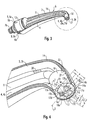
Nachfolgend werden vorteilhafte Ausgestaltungen der Erfindung anhand von vorteilhaften Ausführungsbeispielen und Zeichnungen näher erläutert. Es zeigt. - Fig. 1
- ein erfindungsgemäßes Handstück in der Form eines Kanülenhandstücks in perspektivischer Seitenansicht;
- Fig. 2
- die Kanüle des Handstücks im axialen Längsschnitt;
- Fig. 3
- die Kanüle im axialen Längsschnitt und in perspektivischer Darstellung;
- Fig. 4
- den vorderen Endbereich der Kanüle in vergrößerter perspektivischer Darstellung.
- Die Medienleitungen 3, 4 erstrecken sich im Handstückkörper 2 von dessen hinteren Endbereich zu dessen vorderen Endbereich, wobei sie an Austrittsöffnungen münden, die auf die mit dem Handstück 1 einwirkende Operationsstelle gerichtet sind, um in deren Bereich eine Blasfunktion, eine Spülfunktion oder eine Kühlfunktion auszuführen. Die Lichtabstrahlfläche 5a ist ebenfalls auf die Behandlungsstelle gerichtet ist, um diese zu beleuchten.
- Beim in den Figuren dargestellten Ausführungsbeispiel, bei dem das Handstück 1 ein Kanülenhandstück ist, befinden sich die Austrittsöffnungen 3a, 4a der Medienleitungen 3, 4 und die Lichtabstrahlfläche 5a der Beleuchtungseinrichtung 5 an der Stirnseite einer den vorderen Endbereich des Handstückkörpers 2 bildenden Kanüle 6, die durch eine lösbare Kupplungsvorrichtung 7 in Form einer Schnellschlußverbindung mit dem vorderen Ende eines sich ebenfalls länglich erstreckenden Griffteils 8 lösbar verbunden ist, das den hinteren Bereich des Handstückkörpers 2 bildet. Die Kanüle 6 kann jedoch auch unlösbar oder einteilig mit dem Griffteil 8 verbunden sein. Außerdem erstreckt sich beim Ausführungsbeispiel die Kanüle 6 gekrümmt zu einer Seite des Handstückkörpers 2 hin, wodurch sie sich insbesondere für eine dentalmedizinische Behandlung im Mundraum eines Patienten eignet. Im Rahmen der Erfindung kann die Kanüle 6 sich jedoch auch in einer anderen Form und Richtung erstrecken, z. B. gerade.
- Die Kupplungsvorrichtung 7 ist vorzugsweise eine selbsttätig verrastende Steckkupplung, insbesondere eine an sich bekannte Steck/Drehkupplung mit einer Kupplungsausnehmung 7a an dem einen Teil und einem darin einsteckbaren und drehbaren Kupplungszapfen 7b an dem anderen Teil, wobei vorzugsweise der Kupplungszapfen 7b von der Kanüle 6 nach hinten absteht und die Kupplungsausnehmung 7a im vorderen Endbereich des Griffteils 8 angeordnet ist und nach vorne ausmündet.
- Zur Verrastung der Kanüle 6 im gekuppelten Zustand können ein oder mehrere in
Fig. 3 dargestellte Rastnasen 9a einer Verrastungsvorrichtung 9, z. B. in Form von Federzungen 9b, insbesondere im hinteren Endbereich der Kanüle 6, angeordnet sein, die an nicht dargestellten Gegenrastelementen des Griffteils 8 verrasten. - Die Beleuchtungseinrichtung 5 weist vorzugsweise einen Lichtleiter 11 auf, der im Handstückkörper 2 angeordnet und einer nicht dargestellten Lichtquelle vorgeordnet ist und sich nach vorne bis zu einer Austrittsfläche 12 erstreckt, die vorzugsweise eine ebene Fläche ist und beim Ausführungsbeispiel eines Handstücks 1 mit einer Kanüle 6 die Stirnfläche der Kanüle 6 bildet. Bei einem Kanülenhandstück sind das hintere Ende des Lichtleiters 11 im hinteren Ende der Kanüle 6 und die Lichtquelle im Griffteil 8 angeordnet.
- Die Hauptteile der Kanüle 6 sind ein Basisteil 13, das, z.B. mit dem von ihm nach hinten abstehenden Kupplungszapfen 7b, einen Kanülenfuß bildet, ein vorzugsweise seitlich gekrümmter und z. B. nach vorne verjüngter Kanülenmantel 14, der Lichtleiter 11, der sich im wesentlichen zentral in einem Durchgangsloch 15 im Basisteil 13 und dann im Hohlraum 16 des Kanülenmantels 14 sowie durch ein weiteres Durchgangsloch 17 in einer im vorderen Endbereich des Kanülenmantels 14 sitzenden Innenhülse 18 bis zur Stirnfläche der Kanüle 6 erstreckt, und zwei die Medienleitungen 3, 4 längsabschnittsweise bildende Hohlleitungen 3b, 4b, die an sich im Basisteil 13 erstreckenden Längskanälen 3c, 4c angeschlossen sind und sich vorzugsweise ebenfalls bis zur die Stirnfläche der Kanüle 6 bildenden Austrittsfläche 12 erstrecken und mit ihren Austrittsöffnungen 3a, 4a in der Austrittsfläche 12 münden. Die Hohlleitungen 3b, 4b erstrecken sich ebenfalls durch das Durchgangsloch 17 in der Innenhülse 18, das für den Lichtleiter 11 und die Hohlleitungen 3b, 4b ein gemeinsames Durchgangsloch 17 bildet. Die rückseitige Verbindung der Hohlleitungen 3b, 4b mit den Längskanälen 3c, 4c kann durch Steckverbindungen 3d, 4d erfolgen, bei denen die Hohlleitungen 3b, 4b auf oder in entsprechende Verbindungselemente auf- oder eingesteckt sind. Bei den Hohlleitungen 3b, 4b kann es sich um Röhrchen oder Schläuche handeln, die z. B. aus Metall oder Kunststoff bestehen können.
- Der Lichtleiter 11 weist im Bereich des Basisteils 13 einen kreisrunden Querschnitt auf, und er ist mit geringem Bewegungsspiel in das Durchgangsloch 15 mit einem entsprechenden kreisrunden Querschnitt von vorne eingesteckt und abgedichtet, z. B. mittels einer Ringdichtung 19, die einen Dichtring aufweist, der in einer Ringnut in der Lochwandung sitzt. In der Durchströmrichtung hinter dem Basisteil 13 ändert der Lichtleiter 11 seine Querschnittsform derart, daß er in seinem vorderen Endbereich in der einen Querrichtung q1 eine vergrößerte Breite a und in der anderen quer dazu gerichteten Querrichtung q2 eine Breite b aufweist, die geringer ist als die vergrößerte Breite a. Dabei erstreckt sich der Lichtleiter 11 in diesem mit 11a bezeichneten Endbereich mit einem taillierten Stegabschnitt 11b zwischen den Hohlleitern 3b, 4b, so dass diese sich an den Breitseiten des Lichtleiters 11 befinden. Dabei ist die vergrößerte Breite a größer als die vorzugsweise kreisrunde Querschnittsgröße c der Hohlleiter 3b, 4b, wobei der eine Hohlleiter 3b, insbesondere für Luft, eine größere Querschnittsgröße c als der andere Hohlleiter 4b aufweisen kann. In diesem Endbereich 11a weist der Lichtleiter 11 vorzugsweise im wesentlichen mittig angeordnete Längsnuten 11c auf, deren Querschnittsform und Größe vorzugsweise an die Querschnittsform und Größe der Hohlleitungen 3b, 4b angepaßt ist, so dass diese direkt an den Flächen der Längsnuten 11c anliegen. Das Durchgangsloch 17 weist deshalb eine Querschnittform mit vier einander diametral gegenüberliegenden Lochabschnitten 17a, 17b, 17c, 17d, die in ihren einander zugewandten Innenbereichen ineinander übergehen. Hierdurch hat das Durchgangsloch 17 eine Querschnittsform, die im wesentlichen die Form eines vierblätterigen Kleeblatts ist. Wie bereits beschrieben, weisen die mit 17b, 17d bezeichneten Lochabschnitte eine gerundete, vorzugsweise eine halbkreisförmige Querschnittsform auf, wobei auch die Längsnuten 11c eine halbkreisförmige Querschnittsform haben. Hierdurch ist gewährleistet, dass die Ränder der Längsnuten 11c nicht wesentlich außerhalb der sich parallel zueinander erstreckenden Längsmittelebenen E1, E2 der Hohlleitungen 3b, 4b angeordnet sind und deshalb sowohl ein radiales Einsetzen der Hohlleitungen 3b, 4b von radial außen in die Längsnuten 11c möglich ist und Freiräume zwischen den Hohlleitungen 3b, 4b und Nutwänden vermieden werden oder vermindert sind. Die Tiefe t der Längsnuten 11c entspricht vorzugsweise etwa der halben Querschnittsabmessung c des zugehörigen Hohlleiters 3b, 4b.
- Die mit E3 bezeichnete und die Längsachsen der Längsnuten 11c und der Hohlleitungen 3b, 4b enthaltende Längsebene, insbesondere Längsmittelebene, ist vorzugsweise etwa in der Ebene der Krümmung oder Abwinklung des Handstücks 1 bzw. der Kanüle 6 angeordnet.
- Die einander gegenüberliegenden Endbereiche 11d des Stegabschnitts 11b sind bezüglich dem Abstand d der Hohlleitungen 3b, 4b erweitert, so dass die Querschnittsform des Lichtleiters 11 in etwa der Form eines sogenannten Hundeknochens entspricht. Die zugehörigen Durchgangslochabschnitte 17a, 17c weisen vorzugsweise ebenfalls eine gerundete Querschnittsform auf, insbesondere eine ellipsenförmige Querschnittsform. Die Formgebung ist so ausgebildet, dass der Lichtleiterabschnitt 11a und die Hohlleitungen 3b, 4b das Durchgangsloch 17 im wesentlichen formschlüssig ausfüllen. Um zu vermeiden, dass Verunreinigungen, z. B. Körperflüssigkeiten, durch Spalte des Durchgangslochs 17 in die Kanüle 6 gelangen, ist das Durchgangsloch 17 abgedichtet. Hierdurch wird auch ein Fluten bzw. Eindringen von heißem Wasserdampf während eines Thermodesinfektionsvorgangs vermieden. Die Abdichtung kann z. B. durch ein in die Fugen eingeführtes Dichtmittel z. B. ein Kleber, erfolgen, das den Lichtleiter 11, die Hohlleitungen 3b, 4b und die Innenhülse 18 zu einer Baueinheit verbinden kann, die vorzugsweise vorfertigbar ist.
- Aus den vorgenannten Gründen kann auch die Innenhülse 18 in dem sie aufnehmenden Lochabschnitt 21 abgedichtet, z. B. verklebt, sein. Der Lochabschnitt 21 ist vorzugsweise innen durch eine Stufenfläche 22 begrenzt, an der die Innenhülse 18 anliegt und positioniert ist.
- Die beim Ausführungsbeispiel vorzugsweise durch Hohlleitungen 3b, 4b gebildeten Medienleitungen 3, 4 münden mit aufeinanderzu geneigten Längsachsen aus dem Handstückkörper 2 bzw. der Kanüle 6 aus. Der Austritts-Neigungswinkel W1 bezüglich der vorhandenen Längsrichtung kann z. B. etwa 8° betragen, wobei die Achsen bzw. Austrittsströme sich in einem Abstand e von den Austrittsöffnungen 3a, 4a schneiden bzw. kreuzen und einen Winkel W2 von etwa 16° einschließen. Wie aus
Fig. 2 erkennbar ist, sind nur die Endabschnitte der Hohlleitungen 3b, 4b aufeinanderzu geneigt. - Im Hohlraum 16 ist zur Positionierung wenigstens des Lichtleiters 11 ein Distanzstück 20 zwischen dem Kanülenmantel 14 und in dem Lichtleiter 11 oder auch dem oder den Hohlleitern 3b, 4b angeordnet.
- Vorzugsweise befinden sich die Stirnfläche 14a des Kanülenmantels 14, die Stirnfläche 18a der Hülse 18, die Stirnflächen 3e, 4e der Hohlleitungen 3b, 4b und die Stirnfläche 11e des Lichtleiters 11 in der gemeinsamen und vorzugsweise ebenen Austrittsfläche 12, die beim Ausführungsbeispiel in Form einer Kanüle 6 deren Stirnfläche bildet. Hierdurch werden Vorsprünge, Vertiefungen und Kanten vermieden, was nicht nur eine schonende Behandlung der Behandlungsstellen ermöglicht, sondern es läßt sich auch die Reinhaltung, Desinfektion oder Sterilisation wenigstens des vorderen Endbereichs erleichtern und verbessern. Der Übergang zwischen der Stirnfläche und der sich daran anschließenden Mantelfläche ist vorzugsweise durch eine Fase 14b gebrochen oder gerundet.
- Dem Handstück 1 ist vorzugsweise im vorderen Bereich des Griffteils 8 wenigstens ein Betätigungselement 23, z. B. eine Drucktaste, zugeordnet, durch dessen manuelle Betätigung ein nicht dargestelltes Ventil in der zugehörigen Medienleitung 3, 4 geöffnet wird, um den Medienaustritt einzuschalten. Die Abschaltung kann z. B. dadurch erfolgen, dass das zugehörige Ventil schließt, wenn das Betätigungselement 23 losgelassen wird. Eine solche Betätigungsvorrichtung kann beim Vorhandensein von mehreren Medienleitungen jeweils in der entsprechenden Anzahl vorgesehen sein. Wie aus
Fig. 1 zu erkennen ist, sind zwei Betätigungselemente 23 auf Umfang des Griffteils 8 angeordnet, vorzugsweise auf der der abgewinkelten oder gekrümmten Kanülenspitze abgewandten Seite des Handstücks 1. - Der vom Kanülenmantel 14 umgebene Hohlraum 16 der Kanüle 6 ist rückseitig durch das Basisteil 13 verschlossen, das von hinten in den Kanülenmantel fest eingesetzt ist und durch eine Ringdichtung 24 abgedichtet ist, die z. B. durch einen Dichtring gebildet ist, der in einer Ringnut im Basisteil 13 sitzt.
- Die Federarme 9b der Verrastungsvorrichtung 9 sind vorzugsweise durch segmentförmige Umfangsabschnitte des Basisteils 13 gebildet, die durch die Anordnung einer nach hinten ausmündenden Ringnut 25 gebildet sind.
- Die Kupplungsvorrichtung 7 mit dem Kupplungszapfen 7d ist in Form einer Steck/Drehkupplung an sich bekannt und braucht deshalb nicht näher beschrieben zu werden. Wesentlich ist, daß die Steck/Drehkupplung Z-förmige Durchgangskanäle für die wenigstens eine Medienleitung 3, 4 aufweist, die in bekannter weise die zylindrische oder stufenzylindrische Teilungsfuge zwischen dem Kupplungszapfen 7b und der Kupplungsausnehmung 7a Z-förmig durchsetzen und durch in
Fig. 2 dargestellte Dichtringe von die Teilungsfuge abdichtenden Ringdichtungen abgedichtet ist. Der Z-förmige Verlauf der Medienleitungen ist inFig. 2 strichpunktiert angedeutet. - Nachfolgend werden noch weitere Vorteile des erfindungsgemäßen Handstücks 1 benannt.
- Die Beleuchtungsvorrichtung 5: Die erfindungsgemäße Anordnung des Lichtleiters 11 und der wenigstens einen Medienleitung 3 bzw. 4 ermöglicht eine gute direkte Beleuchtung ohne Abschattung, wobei die Beleuchtung mit einer hohen Lichtintensität erfolgt, weil eine verhältnismäßig große Lichtabstrahlfläche vorhanden ist und das Licht mit wenig Verlust von der Lichtquelle bis zum Objekt (Zahn) geleitet wird. Hierzu trägt auch die vorzugsweise ebene und gemeinsame Abstrahlfläche 12 bei, die eine gute Reinigung bei geringem Reinigungsaufwand ermöglicht.
- Um die Beleuchtung an unterschiedliche Behandlungsmaßnahmen anpassen zu können, ist es vorteilhaft, eine nicht dargestellte Einstellvorrichtung vorzusehen, die es ermöglicht, die Lichtintensität wahlweise zu verringern und zu vergrößern.
- Medienzuführung: Das erfindungsgemäße Handstück 1 ermöglicht es, wahlweise Wasser, trockene Luft oder ein Spray der Behandlungsstelle zuzuführen. Da die erfindungsgemäße Ausgestaltung der Mündungsöffnungen unempfindlich gegen Verschmutzung ist, wird eine konstante Sprayqualität erreicht.
- Hygiene: Die erfindungsgemäße Ausgestaltung im Bereich der vorzugsweise glatten Austrittsfläche 12 ermöglicht auch eine gute Wisch-Desinfizierbarkeit des Austrittsbereichs 1 bzw. der Kanüle 6. Da die vom Medium kontaktierten Bauteile eine Keime reduzierende Wirksamkeit auf das zugehörige Medium ausüben, insbesondere aus Ag-Ion bestehen, wird die Hygiene gefördert und verbessert.
- Da im übrigen im Bereich des Medienaustritts aus dem Handstück 1 bzw. aus der Kanüle 6 keine offenen Toträume vorhanden sind, ist eine Thermodesinfektion möglich und vorteilhaft.
Claims (11)
- Medizinisches, insbesondere dentalmedizinisches, Handstück (1), in dem sich ein Lichtleiter (11) und wenigstens zwei Medienleitungen (3, 4) nach vorne erstrecken und im vorderen Bereich des Handstücks (1) an zwei voneinander getrennten Austrittsöffnungen (3a, 4a) austreten,
wobei die Medienleitungen (3, 4) derart ausgerichtet sind, dass die abgegebenen Medien in einem bestimmten Abstand (e) vor den Austrittsöffnungen (3a, 4a) aufeinander treffen, um einen Spray zu erzeugen,
wobei der Lichtleiter (11) und die Medienleitungen (3, 4) sich bis zu einer gemeinsamen Austrittsfläche (12) erstrecken,
wobei der Lichtleiter (11) in seinem vorderen Endbereich (11a) wenigstens zwei Längsnuten (11c) aufweist, in die die durch Hohlleitungen (3b, 4b) gebildeten Medienleitungen (3, 4) radial einsetzbar sind. - Handstück nach Anspruch 1,
dadurch gekennzeichnet,
dass die Austrittsfläche (12) eine ebene Fläche ist. - Handstück nach Anspruch 1 oder 2,
dadurch gekennzeichnet,
dass die wenigstens eine Hohlleitung (3b, 4b) eine runde Querschnittsform aufweist, wobei die Querschnittsgrößen (c) von z. B. zwei Hohlleitungen (3b, 4b) unterschiedlich sein können. - Handstück nach einem der vorherigen Ansprüche 1 bis 3,
dadurch gekennzeichnet,
dass zwei vorhandene Längsnuten (11c) einen sich in die Umfangsrichtung erstreckenden Abstand voneinander aufweisen, sich vorzugsweise einander gegenüberliegen. - Handstück nach einem der vorherigen Ansprüche 1 bis 4,
dadurch gekennzeichnet,
dass die Querabmessung (a) des Lichtleiters (11), die sich quer zu einer die Längsachsen der Längsnuten (11c) oder der Hohlleitungen (3b, 4b) enthaltenden Längsebene (E3) des Handstücks (1) erstreckt, größer ist als die sich parallel zur Längsmittelebene (E3) erstreckende Querabmessung (b) des Lichtleiters (11). - Handstück nach einem der vorherigen Ansprüche 1 bis 5,
dadurch gekennzeichnet,
dass die Tiefe (t) der wenigstens zwei Längsnuten (11c) im wesentlichen nicht größer ist als die halbe Querschnittsabmessung (c) der zugehörigen Hohlleitung (3b) bzw. (4b). - Handstück nach einem der vorherigen Ansprüche 1 bis 6,
dadurch gekennzeichnet,
dass ein vorderer Endbereich oder eine Kanüle (6) des Handstücks (1) seitlich gekrümmt oder abgewinkelt ist und die die Längsachsen der Hohlleitungen (3b, 4b) enthaltende Längsebene (E3) sich im wesentlichen in der Ebene der Krümmung oder Abwinklung erstreckt. - Handstück nach einem der Ansprüche 1 bis 7,
dadurch gekennzeichnet,
dass der Lichtleiter (11) und die Hohlleitungen (3b, 4b) wenigstens in ihrem vorderen Endbereich von einer Hülse (14) oder Innenhülse (18) umgeben sind. - Handstück nach Anspruch 8,
dadurch gekennzeichnet,
dass der Lichtleiter (11) und die Hohlleitungen (3b, 4b) an Innenmantelflächenabschnitten der Hülse (18) anliegen, die an die Form der zugewandten Mantelflächenabschnitte des Lichtleiters (11) und der Hohlleitungen (3b, 4b) angepaßt sind. - Handstück nach Anspruch 8 oder 9,
dadurch gekennzeichnet,
dass die Hülse (18) an ihrem inneren Ende an einer Schulterfläche (22) des sie aufnehmenden Loches anliegt. - Handstück nach einem der vorherigen Ansprüche,
dadurch gekennzeichnet,
dass die Austrittsöffnungen (3a, 4a) an der Stirnseite einer Kanüle (6) angeordnet sind.
Priority Applications (1)
| Application Number | Priority Date | Filing Date | Title |
|---|---|---|---|
| SI200832019T SI2124812T1 (sl) | 2007-02-14 | 2008-02-12 | Medicinski, zlasti zobnomedicinski ročnik z dvema med seboj ločenima izstopnima odprtinama za medije |
Applications Claiming Priority (2)
| Application Number | Priority Date | Filing Date | Title |
|---|---|---|---|
| DE102007007340A DE102007007340A1 (de) | 2007-02-14 | 2007-02-14 | Medizinisches, insbesondere dentalmedizinisches, Handstück mit zwei voneinander getrennten Austrittsöffnungen für Medien |
| PCT/EP2008/001065 WO2008098740A1 (de) | 2007-02-14 | 2008-02-12 | Medizinisches, insbesondere dentalmedizinisches,handstück mit zwei voneinander getrennten austrittsöffnungen für medien |
Publications (2)
| Publication Number | Publication Date |
|---|---|
| EP2124812A1 EP2124812A1 (de) | 2009-12-02 |
| EP2124812B1 true EP2124812B1 (de) | 2018-11-14 |
Family
ID=38667457
Family Applications (1)
| Application Number | Title | Priority Date | Filing Date |
|---|---|---|---|
| EP08715740.0A Active EP2124812B1 (de) | 2007-02-14 | 2008-02-12 | Medizinisches, insbesondere dentalmedizinisches, handstück mit zwei voneinander getrennten austrittsöffnungen für medien |
Country Status (4)
| Country | Link |
|---|---|
| EP (1) | EP2124812B1 (de) |
| DE (1) | DE102007007340A1 (de) |
| SI (1) | SI2124812T1 (de) |
| WO (1) | WO2008098740A1 (de) |
Cited By (1)
| Publication number | Priority date | Publication date | Assignee | Title |
|---|---|---|---|---|
| DE102021124619A1 (de) | 2021-09-23 | 2023-03-23 | Kavo Dental Gmbh | Medizinische kanüle zur abgabe von medien |
Families Citing this family (2)
| Publication number | Priority date | Publication date | Assignee | Title |
|---|---|---|---|---|
| GB201009644D0 (en) * | 2010-06-09 | 2010-07-21 | Astek Innovations Ltd | Improved dental nozzle |
| DE102011001597B4 (de) * | 2011-03-28 | 2016-09-22 | Aluplast Gmbh | Klebedüse mit mehreren Austrittsöffnungen sowie Verfahren zum Einbringen von Klebmaterial |
Citations (1)
| Publication number | Priority date | Publication date | Assignee | Title |
|---|---|---|---|---|
| DE3734862A1 (de) * | 1987-10-14 | 1989-04-27 | Kaltenbach & Voigt | Zahnaerztliches spritzhandstueck |
Family Cites Families (7)
| Publication number | Priority date | Publication date | Assignee | Title |
|---|---|---|---|---|
| FR1285767A (fr) * | 1961-04-06 | 1962-02-23 | Siemens Reiniger Werke Ag | Pièce à main de projection et de pulvérisation pour soins dentaires |
| US3397457A (en) | 1965-01-22 | 1968-08-20 | Iota Cam Corp | Dental drill |
| DE3337166A1 (de) * | 1983-10-12 | 1985-04-25 | Siemens Ag | Zahnaerztliches spritzhandstueck |
| DE3500085C2 (de) | 1985-01-03 | 1995-06-22 | Kaltenbach & Voigt | Zahnärztliches Funktionshandstück |
| US6305934B1 (en) * | 2000-10-11 | 2001-10-23 | Bill H. Hatley, Jr. | Multifunction syringe for repairing teeth |
| DE10238555A1 (de) * | 2002-08-22 | 2004-03-04 | Kaltenbach & Voigt Gmbh & Co. Kg | Funktionshandstück mit einem Lichtabstrahlelement an seinem vorderen Ende |
| US20050048436A1 (en) | 2003-08-29 | 2005-03-03 | Udi Fishman | Handpiece apparatus and method for dispensing media |
-
2007
- 2007-02-14 DE DE102007007340A patent/DE102007007340A1/de not_active Withdrawn
-
2008
- 2008-02-12 SI SI200832019T patent/SI2124812T1/sl unknown
- 2008-02-12 EP EP08715740.0A patent/EP2124812B1/de active Active
- 2008-02-12 WO PCT/EP2008/001065 patent/WO2008098740A1/de not_active Ceased
Patent Citations (1)
| Publication number | Priority date | Publication date | Assignee | Title |
|---|---|---|---|---|
| DE3734862A1 (de) * | 1987-10-14 | 1989-04-27 | Kaltenbach & Voigt | Zahnaerztliches spritzhandstueck |
Cited By (1)
| Publication number | Priority date | Publication date | Assignee | Title |
|---|---|---|---|---|
| DE102021124619A1 (de) | 2021-09-23 | 2023-03-23 | Kavo Dental Gmbh | Medizinische kanüle zur abgabe von medien |
Also Published As
| Publication number | Publication date |
|---|---|
| DE102007007340A1 (de) | 2008-08-21 |
| SI2124812T1 (sl) | 2019-01-31 |
| WO2008098740A1 (de) | 2008-08-21 |
| EP2124812A1 (de) | 2009-12-02 |
Similar Documents
| Publication | Publication Date | Title |
|---|---|---|
| EP0373111B1 (de) | Einrichtung zur Behandlung eines Knochens, insbesondere Kieferknochens, und/oder Zahns | |
| DE3500444C2 (de) | Vorrichtung zum Einführen eines Endoskops oder eines chirurgischen Werkzeugs in Körperhöhlen mit einer Zufuhr für ein Spülmedium und einer Absaugung für dieses Spülmedium | |
| EP1250106B1 (de) | Spülkanüle zum spülen eines wurzelkanals eines zahnes | |
| EP1391182A2 (de) | Funktionshandstück mit einem Lichtabstrahlelement an seinem vorderen Ende | |
| EP1159928B1 (de) | Medizinisches Handstück mit einem stabförmigen Griffteil | |
| DE10208691A1 (de) | Medizinisches oder dentalmedizinisches Handstück mit einem hinteren und einem vorderen Schaftabschnitt, die einen stumpfen Winkel zwischen sich einschließen | |
| DE10229650A1 (de) | Medizinisches oder dentalmedizinisches Handstück mit einem hinteren und einem vorderen Handstückabschnitt | |
| EP2130485B1 (de) | Medizinisches Instrument | |
| EP4404868B1 (de) | Dentalmedizinische kanüle für dentalspritze zur abgabe von medien und herstellungsverfahren für eine dentalmedizinische kanüle | |
| WO2008098740A1 (de) | Medizinisches, insbesondere dentalmedizinisches,handstück mit zwei voneinander getrennten austrittsöffnungen für medien | |
| DE10108565A1 (de) | Medizinisches oder dentalmedizinisches Behandlungsinstrument mit einem Filterelement | |
| DE4103972C2 (de) | Vorrichtung zum Spülen und Absaugen von Organen des menschlichen und tierischen Körpers | |
| WO2003020149A2 (de) | Medizinisches oder dentalmedizinisches handstück mit einem hinteren und einem vorderen schaftabschnitt, die einen stumpfen winkel zwischen sich einschliessen | |
| DE20309759U1 (de) | Medizinisches Endoskop | |
| DE69608975T2 (de) | Zwischenstück für dentales Handstück | |
| EP2995274B1 (de) | Zahnärztliches Handinstrument und Kopfgehäuse hierfür | |
| EP2524668B1 (de) | Verfahren zum Betreiben eines medizinischen Handgeräts | |
| DE19859217B4 (de) | Elektromotorischer Antrieb für ein chirurgisches Werkzeug | |
| EP1709933B1 (de) | Medizinisches Handstück mit einem abgewinkelten Schaft | |
| EP1669039A1 (de) | Medizinisches längliches Handstück | |
| EP3064158B1 (de) | Medizinische Vorrichtung mit Wasserstrahlapplikator und Verfahren zur Aufrüstung einer chirurgischen Schere | |
| DE10045115B4 (de) | Medizinisches,insbesondere dentalmedizinisches Handstück | |
| DE19756629C2 (de) | Instrument, insbesondere Trokar oder Endoskop | |
| DE202024103652U1 (de) | Zerkleinerungsvorrichtung zur minimal-invasiven Zerkleinerung von Gewebe | |
| DE102007008115A1 (de) | Zahnärztliches Laser-Behandlungsinstrument mit Licht-Auskoppelelement und integrierter Wasserbefeuchtung |
Legal Events
| Date | Code | Title | Description |
|---|---|---|---|
| PUAI | Public reference made under article 153(3) epc to a published international application that has entered the european phase |
Free format text: ORIGINAL CODE: 0009012 |
|
| 17P | Request for examination filed |
Effective date: 20090813 |
|
| AK | Designated contracting states |
Kind code of ref document: A1 Designated state(s): AT BE BG CH CY CZ DE DK EE ES FI FR GB GR HR HU IE IS IT LI LT LU LV MC MT NL NO PL PT RO SE SI SK TR |
|
| DAX | Request for extension of the european patent (deleted) | ||
| 17Q | First examination report despatched |
Effective date: 20160620 |
|
| STAA | Information on the status of an ep patent application or granted ep patent |
Free format text: STATUS: EXAMINATION IS IN PROGRESS |
|
| GRAP | Despatch of communication of intention to grant a patent |
Free format text: ORIGINAL CODE: EPIDOSNIGR1 |
|
| STAA | Information on the status of an ep patent application or granted ep patent |
Free format text: STATUS: GRANT OF PATENT IS INTENDED |
|
| INTG | Intention to grant announced |
Effective date: 20180605 |
|
| GRAJ | Information related to disapproval of communication of intention to grant by the applicant or resumption of examination proceedings by the epo deleted |
Free format text: ORIGINAL CODE: EPIDOSDIGR1 |
|
| STAA | Information on the status of an ep patent application or granted ep patent |
Free format text: STATUS: EXAMINATION IS IN PROGRESS |
|
| GRAR | Information related to intention to grant a patent recorded |
Free format text: ORIGINAL CODE: EPIDOSNIGR71 |
|
| GRAS | Grant fee paid |
Free format text: ORIGINAL CODE: EPIDOSNIGR3 |
|
| STAA | Information on the status of an ep patent application or granted ep patent |
Free format text: STATUS: GRANT OF PATENT IS INTENDED |
|
| GRAA | (expected) grant |
Free format text: ORIGINAL CODE: 0009210 |
|
| STAA | Information on the status of an ep patent application or granted ep patent |
Free format text: STATUS: THE PATENT HAS BEEN GRANTED |
|
| INTC | Intention to grant announced (deleted) | ||
| AK | Designated contracting states |
Kind code of ref document: B1 Designated state(s): AT BE BG CH CY CZ DE DK EE ES FI FR GB GR HR HU IE IS IT LI LT LU LV MC MT NL NO PL PT RO SE SI SK TR |
|
| INTG | Intention to grant announced |
Effective date: 20181005 |
|
| REG | Reference to a national code |
Ref country code: GB Ref legal event code: FG4D Free format text: NOT ENGLISH |
|
| REG | Reference to a national code |
Ref country code: CH Ref legal event code: EP Ref country code: AT Ref legal event code: REF Ref document number: 1063906 Country of ref document: AT Kind code of ref document: T Effective date: 20181115 |
|
| REG | Reference to a national code |
Ref country code: DE Ref legal event code: R096 Ref document number: 502008016453 Country of ref document: DE |
|
| REG | Reference to a national code |
Ref country code: IE Ref legal event code: FG4D Free format text: LANGUAGE OF EP DOCUMENT: GERMAN |
|
| REG | Reference to a national code |
Ref country code: NL Ref legal event code: MP Effective date: 20181114 |
|
| REG | Reference to a national code |
Ref country code: LT Ref legal event code: MG4D |
|
| PG25 | Lapsed in a contracting state [announced via postgrant information from national office to epo] |
Ref country code: HR Free format text: LAPSE BECAUSE OF FAILURE TO SUBMIT A TRANSLATION OF THE DESCRIPTION OR TO PAY THE FEE WITHIN THE PRESCRIBED TIME-LIMIT Effective date: 20181114 Ref country code: LT Free format text: LAPSE BECAUSE OF FAILURE TO SUBMIT A TRANSLATION OF THE DESCRIPTION OR TO PAY THE FEE WITHIN THE PRESCRIBED TIME-LIMIT Effective date: 20181114 Ref country code: BG Free format text: LAPSE BECAUSE OF FAILURE TO SUBMIT A TRANSLATION OF THE DESCRIPTION OR TO PAY THE FEE WITHIN THE PRESCRIBED TIME-LIMIT Effective date: 20190214 Ref country code: ES Free format text: LAPSE BECAUSE OF FAILURE TO SUBMIT A TRANSLATION OF THE DESCRIPTION OR TO PAY THE FEE WITHIN THE PRESCRIBED TIME-LIMIT Effective date: 20181114 Ref country code: NO Free format text: LAPSE BECAUSE OF FAILURE TO SUBMIT A TRANSLATION OF THE DESCRIPTION OR TO PAY THE FEE WITHIN THE PRESCRIBED TIME-LIMIT Effective date: 20190214 Ref country code: IS Free format text: LAPSE BECAUSE OF FAILURE TO SUBMIT A TRANSLATION OF THE DESCRIPTION OR TO PAY THE FEE WITHIN THE PRESCRIBED TIME-LIMIT Effective date: 20190314 Ref country code: LV Free format text: LAPSE BECAUSE OF FAILURE TO SUBMIT A TRANSLATION OF THE DESCRIPTION OR TO PAY THE FEE WITHIN THE PRESCRIBED TIME-LIMIT Effective date: 20181114 |
|
| PG25 | Lapsed in a contracting state [announced via postgrant information from national office to epo] |
Ref country code: SE Free format text: LAPSE BECAUSE OF FAILURE TO SUBMIT A TRANSLATION OF THE DESCRIPTION OR TO PAY THE FEE WITHIN THE PRESCRIBED TIME-LIMIT Effective date: 20181114 Ref country code: GR Free format text: LAPSE BECAUSE OF FAILURE TO SUBMIT A TRANSLATION OF THE DESCRIPTION OR TO PAY THE FEE WITHIN THE PRESCRIBED TIME-LIMIT Effective date: 20190215 Ref country code: PT Free format text: LAPSE BECAUSE OF FAILURE TO SUBMIT A TRANSLATION OF THE DESCRIPTION OR TO PAY THE FEE WITHIN THE PRESCRIBED TIME-LIMIT Effective date: 20190314 Ref country code: NL Free format text: LAPSE BECAUSE OF FAILURE TO SUBMIT A TRANSLATION OF THE DESCRIPTION OR TO PAY THE FEE WITHIN THE PRESCRIBED TIME-LIMIT Effective date: 20181114 |
|
| PGFP | Annual fee paid to national office [announced via postgrant information from national office to epo] |
Ref country code: SI Payment date: 20190124 Year of fee payment: 12 |
|
| REG | Reference to a national code |
Ref country code: SK Ref legal event code: T3 Ref document number: E 29973 Country of ref document: SK |
|
| PG25 | Lapsed in a contracting state [announced via postgrant information from national office to epo] |
Ref country code: DK Free format text: LAPSE BECAUSE OF FAILURE TO SUBMIT A TRANSLATION OF THE DESCRIPTION OR TO PAY THE FEE WITHIN THE PRESCRIBED TIME-LIMIT Effective date: 20181114 Ref country code: PL Free format text: LAPSE BECAUSE OF FAILURE TO SUBMIT A TRANSLATION OF THE DESCRIPTION OR TO PAY THE FEE WITHIN THE PRESCRIBED TIME-LIMIT Effective date: 20181114 |
|
| REG | Reference to a national code |
Ref country code: DE Ref legal event code: R097 Ref document number: 502008016453 Country of ref document: DE |
|
| PG25 | Lapsed in a contracting state [announced via postgrant information from national office to epo] |
Ref country code: RO Free format text: LAPSE BECAUSE OF FAILURE TO SUBMIT A TRANSLATION OF THE DESCRIPTION OR TO PAY THE FEE WITHIN THE PRESCRIBED TIME-LIMIT Effective date: 20181114 Ref country code: EE Free format text: LAPSE BECAUSE OF FAILURE TO SUBMIT A TRANSLATION OF THE DESCRIPTION OR TO PAY THE FEE WITHIN THE PRESCRIBED TIME-LIMIT Effective date: 20181114 |
|
| PLBE | No opposition filed within time limit |
Free format text: ORIGINAL CODE: 0009261 |
|
| STAA | Information on the status of an ep patent application or granted ep patent |
Free format text: STATUS: NO OPPOSITION FILED WITHIN TIME LIMIT |
|
| PGFP | Annual fee paid to national office [announced via postgrant information from national office to epo] |
Ref country code: SK Payment date: 20190123 Year of fee payment: 12 |
|
| REG | Reference to a national code |
Ref country code: CH Ref legal event code: PL |
|
| 26N | No opposition filed |
Effective date: 20190815 |
|
| GBPC | Gb: european patent ceased through non-payment of renewal fee |
Effective date: 20190214 |
|
| PG25 | Lapsed in a contracting state [announced via postgrant information from national office to epo] |
Ref country code: LU Free format text: LAPSE BECAUSE OF NON-PAYMENT OF DUE FEES Effective date: 20190212 Ref country code: MC Free format text: LAPSE BECAUSE OF FAILURE TO SUBMIT A TRANSLATION OF THE DESCRIPTION OR TO PAY THE FEE WITHIN THE PRESCRIBED TIME-LIMIT Effective date: 20181114 |
|
| REG | Reference to a national code |
Ref country code: BE Ref legal event code: MM Effective date: 20190228 |
|
| REG | Reference to a national code |
Ref country code: IE Ref legal event code: MM4A |
|
| PG25 | Lapsed in a contracting state [announced via postgrant information from national office to epo] |
Ref country code: LI Free format text: LAPSE BECAUSE OF NON-PAYMENT OF DUE FEES Effective date: 20190228 Ref country code: CH Free format text: LAPSE BECAUSE OF NON-PAYMENT OF DUE FEES Effective date: 20190228 |
|
| REG | Reference to a national code |
Ref country code: DE Ref legal event code: R082 Ref document number: 502008016453 Country of ref document: DE Representative=s name: MITSCHERLICH, PATENT- UND RECHTSANWAELTE PARTM, DE Ref country code: DE Ref legal event code: R081 Ref document number: 502008016453 Country of ref document: DE Owner name: KAVO DENTAL GMBH, DE Free format text: FORMER OWNER: KALTENBACH & VOIGT GMBH, 88400 BIBERACH, DE |
|
| PG25 | Lapsed in a contracting state [announced via postgrant information from national office to epo] |
Ref country code: GB Free format text: LAPSE BECAUSE OF NON-PAYMENT OF DUE FEES Effective date: 20190214 Ref country code: IE Free format text: LAPSE BECAUSE OF NON-PAYMENT OF DUE FEES Effective date: 20190212 |
|
| PG25 | Lapsed in a contracting state [announced via postgrant information from national office to epo] |
Ref country code: FR Free format text: LAPSE BECAUSE OF NON-PAYMENT OF DUE FEES Effective date: 20190228 Ref country code: BE Free format text: LAPSE BECAUSE OF NON-PAYMENT OF DUE FEES Effective date: 20190228 |
|
| PG25 | Lapsed in a contracting state [announced via postgrant information from national office to epo] |
Ref country code: TR Free format text: LAPSE BECAUSE OF FAILURE TO SUBMIT A TRANSLATION OF THE DESCRIPTION OR TO PAY THE FEE WITHIN THE PRESCRIBED TIME-LIMIT Effective date: 20181114 |
|
| REG | Reference to a national code |
Ref country code: AT Ref legal event code: MM01 Ref document number: 1063906 Country of ref document: AT Kind code of ref document: T Effective date: 20190212 |
|
| PG25 | Lapsed in a contracting state [announced via postgrant information from national office to epo] |
Ref country code: AT Free format text: LAPSE BECAUSE OF NON-PAYMENT OF DUE FEES Effective date: 20190212 |
|
| PG25 | Lapsed in a contracting state [announced via postgrant information from national office to epo] |
Ref country code: MT Free format text: LAPSE BECAUSE OF FAILURE TO SUBMIT A TRANSLATION OF THE DESCRIPTION OR TO PAY THE FEE WITHIN THE PRESCRIBED TIME-LIMIT Effective date: 20181114 |
|
| PG25 | Lapsed in a contracting state [announced via postgrant information from national office to epo] |
Ref country code: CZ Free format text: LAPSE BECAUSE OF NON-PAYMENT OF DUE FEES Effective date: 20200212 Ref country code: SK Free format text: LAPSE BECAUSE OF NON-PAYMENT OF DUE FEES Effective date: 20200212 |
|
| REG | Reference to a national code |
Ref country code: SK Ref legal event code: MM4A Ref document number: E 29973 Country of ref document: SK Effective date: 20200212 |
|
| PG25 | Lapsed in a contracting state [announced via postgrant information from national office to epo] |
Ref country code: SI Free format text: LAPSE BECAUSE OF NON-PAYMENT OF DUE FEES Effective date: 20200213 |
|
| PG25 | Lapsed in a contracting state [announced via postgrant information from national office to epo] |
Ref country code: CY Free format text: LAPSE BECAUSE OF FAILURE TO SUBMIT A TRANSLATION OF THE DESCRIPTION OR TO PAY THE FEE WITHIN THE PRESCRIBED TIME-LIMIT Effective date: 20181114 |
|
| PG25 | Lapsed in a contracting state [announced via postgrant information from national office to epo] |
Ref country code: HU Free format text: LAPSE BECAUSE OF FAILURE TO SUBMIT A TRANSLATION OF THE DESCRIPTION OR TO PAY THE FEE WITHIN THE PRESCRIBED TIME-LIMIT; INVALID AB INITIO Effective date: 20080212 |
|
| REG | Reference to a national code |
Ref country code: FI Ref legal event code: PCE Owner name: KAVO DENTAL GMBH |
|
| PGFP | Annual fee paid to national office [announced via postgrant information from national office to epo] |
Ref country code: FI Payment date: 20251230 Year of fee payment: 19 |
|
| PGFP | Annual fee paid to national office [announced via postgrant information from national office to epo] |
Ref country code: DE Payment date: 20251216 Year of fee payment: 19 |
|
| PGFP | Annual fee paid to national office [announced via postgrant information from national office to epo] |
Ref country code: IT Payment date: 20260122 Year of fee payment: 19 |