EP2127831A2 - Guiding apparatus - Google Patents
Guiding apparatus Download PDFInfo
- Publication number
- EP2127831A2 EP2127831A2 EP09161080A EP09161080A EP2127831A2 EP 2127831 A2 EP2127831 A2 EP 2127831A2 EP 09161080 A EP09161080 A EP 09161080A EP 09161080 A EP09161080 A EP 09161080A EP 2127831 A2 EP2127831 A2 EP 2127831A2
- Authority
- EP
- European Patent Office
- Prior art keywords
- guiding
- axis
- guiding means
- supporting plate
- supporting
- Prior art date
- Legal status (The legal status is an assumption and is not a legal conclusion. Google has not performed a legal analysis and makes no representation as to the accuracy of the status listed.)
- Granted
Links
Images



Classifications
-
- B—PERFORMING OPERATIONS; TRANSPORTING
- B27—WORKING OR PRESERVING WOOD OR SIMILAR MATERIAL; NAILING OR STAPLING MACHINES IN GENERAL
- B27C—PLANING, DRILLING, MILLING, TURNING OR UNIVERSAL MACHINES FOR WOOD OR SIMILAR MATERIAL
- B27C5/00—Machines designed for producing special profiles or shaped work, e.g. by rotary cutters; Equipment therefor
- B27C5/02—Machines with table
- B27C5/04—Guide fences for work
Definitions
- a guiding apparatus of this type is disclosed, for example, in EP 0960686 , filed by the applicant.
- Another object is to make a guiding apparatus that is fixable to a respective machine tool so as to be movable in a non-operating position in which it is disengaged from and completely frees a work plane of said machine.
- the two rotation axes of the supporting means enable the guiding means to be positioned in an operating position and in a further operating position in which the guiding means is centred with respect to the milling tool of the machine.
- the arm can in fact be arranged in two respective positions that are symmetrical with respect to a reference axis passing through the first axis and parallel to the advance direction.
- the lifting means 15 in fact makes a first-class lever in which the first portion 34 and the second portion 35 of the supporting plate constitute the two arms. As the first portion 34 is much shorter than the second portion 35, small rotations of said first portion 34 cause a considerable movement of the guiding means 2, 3 and of the covering means 5 arranged at the end of the second portion 35.
Landscapes
- Life Sciences & Earth Sciences (AREA)
- Engineering & Computer Science (AREA)
- Mechanical Engineering (AREA)
- Wood Science & Technology (AREA)
- Forests & Forestry (AREA)
- Milling, Drilling, And Turning Of Wood (AREA)
- Machine Tool Units (AREA)
Abstract
Description
- The present invention relates to guiding apparatuses for machine tools used in the woodworking industry to make frames, shaped profiled sections, joints, grooves and the like on pieces made of wood or similar materials. In particular, the invention refers to an apparatus for guiding workpieces being machined in a lower vertical milling machine, commonly known as a spindle-moulder.
- Known spindle-moulders comprise a vertical-axis milling tool positioned above a work plane on which the workpieces are placed and moved.
- The simple, or multiple, milling tool is fixed to a spindle shaft driven by a motor that protrudes from the work plane at a rear side of the work plan.
- The machine comprises a guiding apparatus for guiding the workpiece that is provided with sliding guides that are arranged upstream and downstream of the milling tool and define an abutting plane that is substantially perpendicular to the work plane and is parallel to an advance direction of the workpiece.
- The guiding apparatus comprises a supporting plate that supports the sliding guides and a guard of the milling tool. The guides are connected to the supporting plate so as to be adjustable in a direction that is perpendicular to the abutting plane and parallel to the work plane to adjust the position of the workpiece in relation to the milling tool and, thus, a machining or cutting depth.
- The workpiece is generally moved manually by an operator along the advance direction.
- The guides can be adjustable manually or automatically, for example, driven by suitable actuating means.
- In the case of non-rectilinear machinings, for example manual shaping of the workpiece, for which the presence of only the milling tool on the work plane is required, the guiding apparatus has to be removed from the work plane.
- The known guiding apparatuses disclosed above nevertheless require very long and laborious dismantling and assembly procedures that greatly limit the operating flexibility and productivity of the machine.
- In order to overcome this drawback, guiding apparatuses are known that are rotatably fixed to the work plane so as to rotate around an axis that is orthogonal to the aforesaid plane between an operating position, in which the guiding apparatuses abut on and guide the workpieces being machined and a non-operating position, in which the aforesaid apparatuses are spaced apart from the milling tool and arranged outside the work plane.
- Locking means is provided at a free end of the apparatus opposite the rotation axis to fix firmly the supporting body and/or the guides to the work plane in the operating position.
- A guiding apparatus of this type is disclosed, for example, in
EP 0960686 , filed by the applicant. - This apparatus enables the guides and the guard to be moved away from the milling tool rapidly and simply.
- It is nevertheless not possible completely to free the work plane as the portion of the work plane that is rotatably connected to the apparatus in fact always remains engaged, even in the non-operating position. This limits or prevents some type of machining.
- As this apparatus is movable substantially along a circle-arch trajectory, it has the drawback of having only one operating position in which the sliding guides and the guard are centred, i.e. aligned longitudinally and transversely on the milling tool.
- In order to machine workpieces of different dimensions, the apparatus has to be provided with sliding guides provided with a very great adjusting stroke in a transverse direction, this determining an increase in the total dimensions and sizes of the apparatus and an increase in costs, especially if the guides are driven by actuators.
- A further drawback of such an apparatus consists of the fact that it is mounted in a cantilevered manner on the work plane of the machine and consequently requires a particularly stiff and robust supporting structure in order to avoid flexure and/or deformation that could compromise the positioning precision and/or the correct operation thereof. The supporting structure is therefore very heavy and bulky.
- Owing to the imprecisions in making and/or mounting the machine and/or guiding apparatus, the supporting structure of the latter may further flex in the operating position. In this position, in fact, the supporting structure is locked at opposite ends respectively by the rotation axis and by the locking means. The flexure of the supporting structure may cause imprecise and incorrect positioning of the sliding guides.
- Guiding apparatuses are further known that are fixed to the work plane of the machine by an articulated arm comprising two members that are hinged on another. A first member is rotatably fixed to the work plane, whilst the second member rotatably supports the sliding guides and the guard.
- Owing to the three degrees of freedom in rotation of the articulated arm, these guiding apparatuses can be moved further away from the work plane and be spaced away from the machine, nevertheless, they require a very laborious and complex procedure for being precisely positioned in the operating position. The operating position, in fact, owing to the mobility of the operating arm, is not uniquely reachable from the non-operating position.
- In addition to that, the aforesaid apparatuses do not permit the work plane to be freed completely, as a portion thereof remains anyway engaged by the first member of the articulated arm. Further, the two members of the articulated arm superimposed on one another have significant overall dimensions.
- An object of the invention is to improve the guiding apparatuses for spindle-moulder machine tools, in particular increasing the versatility and flexibility of use thereof.
- Another object is to make a guiding apparatus that is fixable to a respective machine tool so as to be movable in a non-operating position in which it is disengaged from and completely frees a work plane of said machine.
- A further object is to obtain a guiding apparatus that is positionable in a rapid, precise and stable manner in two distinct operating positions.
- Still another object is to obtain a guiding apparatus having a light and compact structure and which is at the same time robust and reliable.
- According to the invention a guiding apparatus is provided that is associable with a machine tool for machining elements made of wood or similar material, in particular a spindle-moulder, comprising guiding means supported by supporting means rotatably fixed to said machine such that said guiding means is movable between an operating position in which said guiding means is superimposed on an upper face of a work plane of said machine, for guiding said elements along an advance direction, and a non-operating position, in which said guiding means is spaced apart and does not face said work plane, characterised in that said supporting means comprises an arm provided with a first end, rotatably fixed to said machine around a first axis, and with a second end rotatably supporting said guiding means around a second axis. The first axis and the second axis are substantially parallel and perpendicular to the upper face of the work plane.
- The supporting means is fixed to the machine so as to be arranged completely below the upper face of the work plane. In particular, the first end of the arm is fixable to a side face of the work plane by shelf means.
- Owing to this aspect of the invention it is thus possible to make a guiding apparatus that in the non-operating position completely frees the upper face of the work plane of the machine so as to enable non-rectilinear machinings to be performed, for example manual shaping of the workpiece for which the presence on the work plane of only the milling tool is required.
- The two rotation axes of the supporting means enable the guiding means to be positioned in an operating position and in a further operating position in which the guiding means is centred with respect to the milling tool of the machine. The arm can in fact be arranged in two respective positions that are symmetrical with respect to a reference axis passing through the first axis and parallel to the advance direction. By acting on the supporting means it is thus possible to adjust the position of the guiding means and machine elements having different dimensions without the need to have guiding means available having a very large adjusting stroke. It is thus possible to simplify the structure of the guiding means and reduce the total dimensions and sizes of the apparatus.
- The invention can be better understood and implemented with reference to the attached drawings, which illustrate an embodiment thereof by way of non-limiting example in which:
-
Figure 1 is a top plan view of the guiding apparatus of the invention associated with a machine tool and in an operating position; -
Figure 2 is a side view of the apparatus inFigure 1 , in which the machine is partially shown; -
Figure 3 is a partial rear view of the apparatus inFigure 2 ; -
Figure 4 is an enlarged plan view of the guiding apparatus inFigure 1 , arranged in a further operating position; -
Figure 5 is a partial side view of the guiding apparatus in a raised configuration; -
Figure 6 is an enlarged view of a detail of the apparatus inFigure 5 showing lifting means; -
Figure 7 is a view like that inFigure 6 , in which the guiding apparatus is in a lowered configuration; -
Figure 8 is a top plan view of the apparatus in Figure in a non-operating position; -
Figure 9 is a side view of the apparatus inFigure 8 , in which the machine tool is partially illustrated; -
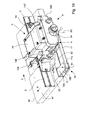
Figure 10 is a perspective view of another embodiment of the guiding apparatus of the invention associated with a work plane of a machine tool and in an operating position; -
Figure 11 is a side view of the apparatus inFigure 10 ; -
Figure 12 is a top plan view of the apparatus inFigure 10 . - With reference to
figures 1 to 9 , there is illustrated a guidingapparatus 1 that is associable with amachine tool 50 formachining elements 100 made of wood or similar material, in particular a lower vertical milling machine, a so-called spindle-moulder, that is provided with amilling tool 55 with a vertical axis that protrudes from awork plane 60 on anupper face 61 of which theaforesaid elements 100 are located and moved. Theupper face 61 is substantially horizontal. - The guiding
apparatus 1 comprises guidingmeans means 10 rotatably fixed to themachine 50 so that the guiding means 2, 3, 4 is movable between an operating position A (Figure 1 ), in which it is superimposed on theupper face 61 of thework plane 60 to guide theelements 100 along an advance direction T, and a non-operating position C (Figure 8 ), in which the guiding means 2, 3, 4 are spaced apart and do not face thework plane 60. - The guiding
means plate 4 supporting first guidingmeans 2 and second guidingmeans 3 arranged, in the operating condition A, respectively upstream and downstream of themilling tool 55, for example aligned one another to form an abutting plane for the elements that is orthogonal to theupper face 61. - The first guiding means 2 and the second guiding means 3 are fixed to the supporting
plate 4 so as to be movable transversely to said advance direction T to adjust, in use, a position of theelements 100 with respect to themilling tool 55 and thus a machining or cutting depth. - In particular, the first guiding means 2 and the second guiding means 3 are independently movable along an adjusting direction S that is substantially orthogonal to the advance direction T.
- The
apparatus 1 comprises first adjusting means 6 and second adjusting means 7 arranged for moving along the adjusting direction S respectively the first guidingmeans 2 and the second guiding means 3. The first adjusting means 6 and the second adjusting means 7 are driven manually and comprise, for example, movement screws of known type that are drivable by handwheels. -
Covering means 5 is also provided that is fixed to the supportingplate 4 and interposed between the first guidingmeans 2 and the second guiding means 3 to contain partially themilling tool 55 in the operating configuration A. - The covering means 5 comprises a
first covering element 13 fixed to the supportingplate 4 and slidably supporting asecond covering element 14 connected to the guiding means 2, 3 and movable therewith in the adjusting direction S. - The supporting means 10 substantially comprises an
arm 11 provided with afirst end 11a, rotatably fixed to thework plane 60 around a first axis X1, and with asecond end 11b rotatably supporting said guiding means 2, 3, 4 around a second axis X2. The first axis X1 and the second axis X2 are substantially parallel to one another and perpendicular to theupper face 61. - The
arm 11 comprises, for example, a tubular element with a rectangular section, thefirst end 11a of which is rotatably fixed to aside face 62 of thework plane 60 by ashelf support 12. The side face 62 is substantially perpendicular to theupper face 61. - The
shelf support 12 comprises two supportingwings first end 11a of thearm 11 is rotatably inserted. Theshelf support 12 is fixed to theside face 62 so that thearm 11 is arranged completely below theupper face 61, i.e. below a horizontal plane M that is coplanar with theupper face 61. The supportingwings upper face 61. - In an embodiment of the
apparatus 1 that is not illustrated in the figures, thearm 11 is rotatably fixed to a base orframe 52 of themachine 50, or to a support of a control panel of the machine. - In a further embodiment of the
apparatus 1 that is not illustrated, thearm 11 is rotatably housed in a notched seat made on theupper face 61 of the work plane and such as to enable theaforesaid arm 11 to remain always below the horizontal plane M. - A
first portion 34 of the supportingplate 4 is rotatably connected, around the second axis X2, to thesecond end 11b of thearm 11, asecond portion 35 of the supportingplate 4 supporting the guiding means 2, 3 and the covering means 5. - It should be noted that in the non-operating position C the guiding
apparatus 1 enables theupper face 61 of thework plane 60 to be freed completely to enable non-rectilinear machinings to be performed on theelement 100, for example manual shaping of the workpiece, for which the presence on thework plane 60 of only the milling tool 55 (Figures 8 and 9 ) is necessary. - As the supporting
plate 4 is rotatable around the second axis X2, the guiding means 2, 3 and the covering means 5 can be rotated in the non-operating position C so as not to interfere with the operator. - As illustrated in
Figure 4 , the supportingmeans 10 enables the guiding means 2, 3 and the covering means 5 to be positioned also in a further operating position B, in which the second end of thearm 11 is nearer thework plane 60. - In the operating position A and in the further operating position B the guiding means 2, 3 and the covering means are centred with respect to the
milling tool 55, i.e. aligned longitudinally and transversely to themilling tool 55, as thearm 11 is arranged in respective symmetrical positions with respect to a reference axis Y, passing through the first axis X1, parallel to the advance direction T and perpendicular to the adjusting direction S. In particular, in the operating position A thearm 10 is rotated clockwise by an angle α with respect to the reference axis Y, whilst in the further operating position B thearm 10 is rotated anticlockwise by the same angle α with respect to the reference axis Y. The angle α is comprised, for example, between 3° and 20°, in particular 8°. - In another embodiment of the
apparatus 1 that is not illustrated in the figures, the length of thearm 11 and the position of themilling tool 55 on thework plane 60 are such that the guidingapparatus 1 has only one further operating position, in which, for example, thearm 11 is arranged parallel to the advance direction T. - The
apparatus 1 is locked in the operating positions A, B by stop pins 38 fixed to the supportingplate 4 and arranged for engaging in respective stop holes provided on theupper face 61 of thework plane 60. - Abutting means 40 is fixed to the
side face 62 to abut on thesecond end 11b of thearm 11 in the further operating position B. The abutting means 40 is adjustable for calibrating the position of the guiding means 2, 3 with respect to themilling tool 55 in the adjusting direction S. - By acting on the supporting means 10 it is thus possible to adjust a position of the guiding means 2, 3, 4 in the adjusting direction S. This enables
elements 100 to be machined that have different dimensions without the need to arrange first guiding means 2 and second guiding means 3 having a very large adjusting stroke. It is thus possible to simplify the structure of the guiding means 2, 3 and of the corresponding movement means 6, 7 and to reduce the total dimensions of and sizes occupied by theapparatus 1. - The guiding
apparatus 1 further comprises lifting means 15, interposed between thesecond end 11b of thearm 11 and the supportingplate 4 for lifting or lowering the supportingplate 4 with respect to theupper face 61 of thework plane 60. In this manner the guiding means 2, 3, 4 can be rotated in an easy and secure manner between the non-operating position C and one of the operating positions A, B without the risk of collisions with thework plane 60, even in the event of flexure of the supportingmeans 10. The supporting means 10 can thus have a relatively light structure with consequent reduction of weight, overall dimensions and costs. The lifting means 15 enables the guiding means 2, 3, 4 and the covering means 5 to be moved between a raised configuration R and a lowered configuration L in which the guiding means 2, 3, 4 is respectively spaced apart from and abutting on saidupper face 61 when the aforesaid guiding means 2, 3, 4 is in one of the operating positions A, B. - The lifting means 15 enables the supporting
plate 4 to be rotated around a third axis X3 that is substantially perpendicular to the first axis X1 and to the second axis X2 and parallel to theupper face 61 and to theside face 62. - The lifting means 15 comprises a
movement screw 16 inserted into a throughhole 17 made on thearm 11, at thesecond end 11b, and connected to theaforesaid arm 11 by anut screw 21. In particular, the throughhole 17 is made on anupper wall 31 and alower wall 32 of the arm, which are opposite and substantially parallel to theupper face 61. - The
movement screw 16 is connected to the supportingplate 4. In particular, themovement screw 16 comprises ahead 16a provided with a lower portion of spherical shape suitable for engaging incomplementary seat 19, made on thefirst portion 34 of the supportingplate 4. Thehead 16a of thescrew 16 and thecomplementary seat 19 in fact form a spherical articulated joint that enables the supportingplate 4 to tilt with respect to themovement screw 16. At the same time the supportingplate 4 is free to rotate around a longitudinal axis of themovement screw 16, this axis coinciding with the second axis X2. - The
nut screw 21 engages on a threadedportion 16b of thescrew 16 and abuts on an internal surface of theupper wall 31 of thearm 11. Abush 18 is fixed to, and contains, thenut screw 21. Acontrol lever 23 is fixed to thebush 18. - The
bush 18 enables thenut screw 21 to be brought into phase with thecontrol lever 23, which is drivable manually. In particular, by acting on thecontrol lever 23 it is possible to rotate thebush 18 andnut screw 21 and move thescrew 16 linearly along the second axis X2, so as to move thefirst portion 34 of the supportingplate 4 away from or towards thearm 11. Due to the mass distributions and the corresponding position of the centre of gravity, the supportingplate 4 always tends to rotate downwards in the lowered configuration L (clockwise in the direction of the arrow F with reference toFigures 6, 7 ). Themovement screw 16, which opposes this rotation in both configurations R, L, is thus subject to traction force. - The lifting means 15 further comprises a further supporting
plate 24 fixed to theupper wall 31 of thearm 11 and provided with a respective hole for the passage of themovement screw 16. - The further supporting
plate 24 is provided with a plurality ofpins plate 24 facing the supportingplate 4 and intended for contacting and supporting the supportingplate 4 in the raised configuration R and in the lowered configuration L. - In particular, the further supporting
plate 24 comprises a pair offirst pins 25 arranged along an internal edge of said further supportingplate 24, nearer theside face 62 of thework plane 60, and a pair ofsecond pins 26 arranged on an external opposite edge. - In the raised configuration R (
Figure 6 ) thefirst portion 34 of the supportingplate 4 abuts on thefirst pins 25 and the second pins 26, protruding from the further supportingplate 24 by the same amount. - The
pins plate 4 in the rotation around the second axis X2. - The
second portion 35 of the supportingplate 4 is rotated by virtue of a folding angle formed by the twoportions plate 4. - The folding angle is for example 178°.
- In the lowered configuration L (
Figure 7 ) thefirst portion 34 of the supportingplate 4 substantially abuts only on thefirst pins 25, which thus act as rotation fulcrums. The third axis X3 is an axis passing through aligned contact portions of the first pins 25. - The lifting means 15 in fact makes a first-class lever in which the
first portion 34 and thesecond portion 35 of the supporting plate constitute the two arms. As thefirst portion 34 is much shorter than thesecond portion 35, small rotations of saidfirst portion 34 cause a considerable movement of the guiding means 2, 3 and of the covering means 5 arranged at the end of thesecond portion 35. - Using the
screw 16 and thenut screw 21 enables considerable traction force to be exerted and a work stroke that is sufficient to rotate the supportingplate 4 to be obtained with limited movement of thelever 23. - It is further possible to increase the width of the rotation of the supporting
plate 4 by arranging thefirst pins 25 that protrude most from the further supportingplate 24 with respect to the second pins 26. - It is pointed out that in the operating position A, B, and in the lowered configuration L, the supporting
plate 4 rests completely on thework plane 60 on which the entire weight of the guidingapparatus 1 thus rests. The supporting means 10 does not therefore support the weight of the guidingapparatus 1 to which they are connected in fact in an articulated and non-rigid manner by virtue of the articulated connection between themovement screw 16 and supportingplate 4. For this reason, when the supportingplate 4 is locked on thework plane 10 by the stop pins 38 in the supportingmeans 10 and in the supportingplate 4 tension states, internal flexure and/or deformation stress are not generated. - With reference to
figures 10 to 12 , there is illustrated another embodiment of the guidingapparatus 1 of the invention that differs from the embodiment disclosed above through the fact that the supportingplate 4 is substantially flat, thefirst portion 34 and thesecond portion 35 being coplanar. - In this case, the lifting means 15 comprises a further supporting
plate 24 in which thefirst pins 25 protrude more than the second pins 26. - This embodiment of the apparatus differs further by the fact that the adjusting means 106, 107 of the transverse position of the guiding means 2, 3 is driven automatically and comprises actuating means 108, 109 of pneumatic or electric type.
- In particular, the first adjusting means 106 acting on the first guiding means 2 is driven by first actuating means 108, whilst the second adjusting means 107 acting on the second guiding means 3 is driven by second actuating means 109.
- In this embodiment of the guiding
apparatus 1, the stroke along the adjusting direction S of the guiding means 2, 3 is sufficiently large as to enable the supporting means 10 to have the same operating position A' in which thearm 11 is substantially parallel to theside face 62 of thework plane 60.
Claims (20)
- Guiding apparatus that is associable with a machine tool for machining elements (100) made of wood or similar material, in particular a spindle-moulder, comprising guiding means (2, 3, 4) supported by supporting means (10) rotatably fixed to said machine (50) such that said guiding means (2, 3, 4) is movable between an operating position (A, B; A') in which said guiding means (2, 3, 4) are superimposed on an upper face (61) of a work plane (60) of said machine (50) for guiding said elements (100) along an advance direction (T), and a non-operating position (C), in which said guiding means (2, 3, 4) is spaced apart and does not face said work plane (60),
characterised in that said supporting means (10) comprises an arm (11) provided with a first end (11a), rotatably fixed to said machine (50) around a first axis (X1), and with a second end (11b) rotatably supporting said guiding means (2, 3, 4) around a second axis (X2). - Apparatus according to claim 1, wherein said first axis (X1) and said second axis (X2) are substantially parallel and perpendicular to said upper face (61).
- Apparatus according to claim 1 or 2, wherein said supporting means (10) is fixed to said machine (50) so as to be completely below said upper face (61).
- Apparatus according to any preceding claim, wherein said first end (11a) of said arm (11) is fixable to a side face (62) of said work plane (60).
- Apparatus according to claim 4, wherein said supporting means (10) comprises shelf means (12) that is fixable to said side face (62) and rotatably supports said arm (11) around said first axis (X1).
- Apparatus according to claim 4 or 5, wherein said side face (62) is substantially perpendicular to said upper face (61).
- Apparatus according to any one of claims 1 to 3, wherein said first end (11a) is fixable to a base (52) of said machine and/or to a support of a control panel of said machine (50).
- Apparatus according to any preceding claim, wherein said guiding means (2, 3, 4) comprises a supporting plate (4) supporting first guiding means (2) and second guiding means (3) arranged in said operating condition (A, B; A') respectively upstream and downstream of a milling tool (55) of said machine (50), said milling tool (55) protruding from said work plane (60).
- Apparatus according to claim 8, wherein said supporting plate (4) is positionable in two operating positions (A, B) in which said first guiding means (2) and second guiding means (3) are centred with respect to said milling tool (55).
- Apparatus according to claim 8 or 9, wherein said first guiding means (2) and said second guiding means (3) are fixed to said supporting plate (4) so as to be movable along an adjusting direction (S) that is transverse to said advance direction (T).
- Apparatus according to any one of claims 8 to 10, comprising covering means (5) of said milling tool (55) fixed to said supporting plate (4).
- Apparatus according to any preceding claim, comprising lifting means (15) interposed between said second end (11b) of said arm (11) and said guiding means (2, 3, 4) for lifting or lowering said guiding means (2, 3, 4) with respect to said upper face (61).
- Apparatus according to claim 12, wherein said lifting means (15) is arranged for rotating said guiding means (2, 3, 4) around a third axis (X3) that is substantially perpendicular to said first axis (X1) and to said second axis (X2) and substantially parallel to said upper face (61).
- Apparatus according to claim 13, as claim 12 is appended to any one of claims 8 to 11, wherein said lifting means (15) comprises screw means (16) connected to a first portion (34) of said supporting plate (4) and engaged with said second end (11b) by nut screw means (21).
- Apparatus according to claim 14, wherein a longitudinal axis of said screw means (16) substantially coincides with said second axis (X2).
- Apparatus according to claim 14 or 15, wherein said lifting means (15) comprises a further supporting plate (24) fixed to said second end (11b) and provided with pin means (25, 26) arranged for abutting on and supporting said first portion (34) of said supporting plate (4).
- Apparatus according to claim 16, as appended to claim 14, wherein said nut screw means (21) is rotatable manually for moving said screw means (16) along said second axis (X2) so as to rotate a supporting plate (4) substantially pivoted on said pin means (25, 26) around said third axis (X3).
- Apparatus according to any one of claims 14 to 17, wherein said screw means (16) is connected to said first portion (34) so as to make a substantially spherical articulated joint (16a, 19).
- Apparatus according to any one of claims 14 to 18, wherein said supporting plate (4) comprises a second portion (35) supporting at least said first guiding means (2) and said second guiding means (3).
- Apparatus according to claim 19, wherein said first portion (34) and said second portion (35) of said supporting plate (4) form a folding angle.
Applications Claiming Priority (1)
| Application Number | Priority Date | Filing Date | Title |
|---|---|---|---|
| ITMO20080156 ITMO20080156A1 (en) | 2008-05-26 | 2008-05-26 | DRIVING SYSTEM |
Publications (3)
| Publication Number | Publication Date |
|---|---|
| EP2127831A2 true EP2127831A2 (en) | 2009-12-02 |
| EP2127831A3 EP2127831A3 (en) | 2014-01-01 |
| EP2127831B1 EP2127831B1 (en) | 2016-05-11 |
Family
ID=40302880
Family Applications (1)
| Application Number | Title | Priority Date | Filing Date |
|---|---|---|---|
| EP09161080.8A Active EP2127831B1 (en) | 2008-05-26 | 2009-05-26 | Machine tool comprising a guiding apparatus |
Country Status (2)
| Country | Link |
|---|---|
| EP (1) | EP2127831B1 (en) |
| IT (1) | ITMO20080156A1 (en) |
Cited By (1)
| Publication number | Priority date | Publication date | Assignee | Title |
|---|---|---|---|---|
| DE102012204309B4 (en) * | 2012-03-19 | 2015-03-26 | Hokubema Maschinenbau Gmbh | moulder |
Citations (1)
| Publication number | Priority date | Publication date | Assignee | Title |
|---|---|---|---|---|
| EP0960686A2 (en) | 1998-05-19 | 1999-12-01 | SCM GROUP S.p.A. | A woodworking machine |
Family Cites Families (2)
| Publication number | Priority date | Publication date | Assignee | Title |
|---|---|---|---|---|
| DE8915948U1 (en) * | 1989-09-19 | 1992-05-21 | Fried Kunststofftechnik GmbH, 7060 Schorndorf | Chip collection device for a table milling machine |
| DE4417378C1 (en) * | 1994-05-18 | 1995-12-07 | Schweiz Unfallversicherung | Working fixture for milling machine handling wooden workpieces |
-
2008
- 2008-05-26 IT ITMO20080156 patent/ITMO20080156A1/en unknown
-
2009
- 2009-05-26 EP EP09161080.8A patent/EP2127831B1/en active Active
Patent Citations (1)
| Publication number | Priority date | Publication date | Assignee | Title |
|---|---|---|---|---|
| EP0960686A2 (en) | 1998-05-19 | 1999-12-01 | SCM GROUP S.p.A. | A woodworking machine |
Cited By (1)
| Publication number | Priority date | Publication date | Assignee | Title |
|---|---|---|---|---|
| DE102012204309B4 (en) * | 2012-03-19 | 2015-03-26 | Hokubema Maschinenbau Gmbh | moulder |
Also Published As
| Publication number | Publication date |
|---|---|
| EP2127831B1 (en) | 2016-05-11 |
| ITMO20080156A1 (en) | 2009-11-27 |
| EP2127831A3 (en) | 2014-01-01 |
Similar Documents
| Publication | Publication Date | Title |
|---|---|---|
| CN108430718B (en) | Woodworking table and multifunctional woodworking device | |
| EP2432618B1 (en) | Machine tool | |
| KR101504460B1 (en) | Jig base for double angle processing | |
| CN100479980C (en) | Machine tool | |
| KR20130034075A (en) | Vise for milling machines with adjustable angle | |
| CN102049564B (en) | Cutting machine and shield assembly thereof | |
| US5005618A (en) | Means for positioning arched halving-joints of frame portions and for milling bevels into these frame portions | |
| US12350746B2 (en) | Transversal table for a woodworking machine and woodworking machine having such a transversal table, and method for controlling a woodworking machine | |
| CN110962034B (en) | A honing tool for a workpiece with a peripheral hole | |
| EP2127831B1 (en) | Machine tool comprising a guiding apparatus | |
| KR102662939B1 (en) | Centering vice | |
| CN102756171A (en) | Oblique saw | |
| CN207915044U (en) | A kind of novel positioning fixture | |
| EP4331770A1 (en) | Operating head and method for machining profiled bars | |
| US4450881A (en) | Roller table for woodworking machines | |
| JP2009527367A (en) | Shaper | |
| CN107336300B (en) | Tenoning machine | |
| CN111774918B (en) | A bar cutting device | |
| EP1040891B1 (en) | A work centre having a plurality of clamps for clamping a work-piece | |
| KR200362763Y1 (en) | Holder for a forging former | |
| CN223789925U (en) | A precision feeding mechanism | |
| CN222680380U (en) | Workpiece clamping device for machining by mechanical machine tool | |
| CN223098639U (en) | Part clamping device for milling and grinding | |
| CN102049567B (en) | Cutting machine and protective cover assembly thereof | |
| CN113001237B (en) | An adjustable hand function arm support guide block arc groove processing tool |
Legal Events
| Date | Code | Title | Description |
|---|---|---|---|
| PUAI | Public reference made under article 153(3) epc to a published international application that has entered the european phase |
Free format text: ORIGINAL CODE: 0009012 |
|
| AK | Designated contracting states |
Kind code of ref document: A2 Designated state(s): AT BE BG CH CY CZ DE DK EE ES FI FR GB GR HR HU IE IS IT LI LT LU LV MC MK MT NL NO PL PT RO SE SI SK TR |
|
| REG | Reference to a national code |
Ref country code: DE Ref legal event code: R079 Ref document number: 602009038559 Country of ref document: DE Free format text: PREVIOUS MAIN CLASS: B27C0005060000 Ipc: B27C0005040000 |
|
| PUAL | Search report despatched |
Free format text: ORIGINAL CODE: 0009013 |
|
| AK | Designated contracting states |
Kind code of ref document: A3 Designated state(s): AT BE BG CH CY CZ DE DK EE ES FI FR GB GR HR HU IE IS IT LI LT LU LV MC MK MT NL NO PL PT RO SE SI SK TR |
|
| RIC1 | Information provided on ipc code assigned before grant |
Ipc: B23Q 3/00 20060101ALI20131128BHEP Ipc: B27C 5/06 20060101ALI20131128BHEP Ipc: B27C 5/04 20060101AFI20131128BHEP |
|
| 17P | Request for examination filed |
Effective date: 20140630 |
|
| RBV | Designated contracting states (corrected) |
Designated state(s): AT BE BG CH CY CZ DE DK EE ES FI FR GB GR HR HU IE IS IT LI LT LU LV MC MK MT NL NO PL PT RO SE SI SK TR |
|
| 17Q | First examination report despatched |
Effective date: 20150218 |
|
| GRAP | Despatch of communication of intention to grant a patent |
Free format text: ORIGINAL CODE: EPIDOSNIGR1 |
|
| INTG | Intention to grant announced |
Effective date: 20151211 |
|
| GRAS | Grant fee paid |
Free format text: ORIGINAL CODE: EPIDOSNIGR3 |
|
| GRAA | (expected) grant |
Free format text: ORIGINAL CODE: 0009210 |
|
| AK | Designated contracting states |
Kind code of ref document: B1 Designated state(s): AT BE BG CH CY CZ DE DK EE ES FI FR GB GR HR HU IE IS IT LI LT LU LV MC MK MT NL NO PL PT RO SE SI SK TR |
|
| REG | Reference to a national code |
Ref country code: GB Ref legal event code: FG4D |
|
| REG | Reference to a national code |
Ref country code: CH Ref legal event code: EP |
|
| REG | Reference to a national code |
Ref country code: AT Ref legal event code: REF Ref document number: 798281 Country of ref document: AT Kind code of ref document: T Effective date: 20160515 |
|
| REG | Reference to a national code |
Ref country code: IE Ref legal event code: FG4D |
|
| REG | Reference to a national code |
Ref country code: DE Ref legal event code: R096 Ref document number: 602009038559 Country of ref document: DE |
|
| REG | Reference to a national code |
Ref country code: LT Ref legal event code: MG4D |
|
| REG | Reference to a national code |
Ref country code: NL Ref legal event code: MP Effective date: 20160511 |
|
| PG25 | Lapsed in a contracting state [announced via postgrant information from national office to epo] |
Ref country code: FI Free format text: LAPSE BECAUSE OF FAILURE TO SUBMIT A TRANSLATION OF THE DESCRIPTION OR TO PAY THE FEE WITHIN THE PRESCRIBED TIME-LIMIT Effective date: 20160511 Ref country code: NL Free format text: LAPSE BECAUSE OF FAILURE TO SUBMIT A TRANSLATION OF THE DESCRIPTION OR TO PAY THE FEE WITHIN THE PRESCRIBED TIME-LIMIT Effective date: 20160511 Ref country code: LT Free format text: LAPSE BECAUSE OF FAILURE TO SUBMIT A TRANSLATION OF THE DESCRIPTION OR TO PAY THE FEE WITHIN THE PRESCRIBED TIME-LIMIT Effective date: 20160511 Ref country code: NO Free format text: LAPSE BECAUSE OF FAILURE TO SUBMIT A TRANSLATION OF THE DESCRIPTION OR TO PAY THE FEE WITHIN THE PRESCRIBED TIME-LIMIT Effective date: 20160811 |
|
| PG25 | Lapsed in a contracting state [announced via postgrant information from national office to epo] |
Ref country code: HR Free format text: LAPSE BECAUSE OF FAILURE TO SUBMIT A TRANSLATION OF THE DESCRIPTION OR TO PAY THE FEE WITHIN THE PRESCRIBED TIME-LIMIT Effective date: 20160511 Ref country code: ES Free format text: LAPSE BECAUSE OF FAILURE TO SUBMIT A TRANSLATION OF THE DESCRIPTION OR TO PAY THE FEE WITHIN THE PRESCRIBED TIME-LIMIT Effective date: 20160511 Ref country code: SE Free format text: LAPSE BECAUSE OF FAILURE TO SUBMIT A TRANSLATION OF THE DESCRIPTION OR TO PAY THE FEE WITHIN THE PRESCRIBED TIME-LIMIT Effective date: 20160511 Ref country code: LV Free format text: LAPSE BECAUSE OF FAILURE TO SUBMIT A TRANSLATION OF THE DESCRIPTION OR TO PAY THE FEE WITHIN THE PRESCRIBED TIME-LIMIT Effective date: 20160511 Ref country code: GR Free format text: LAPSE BECAUSE OF FAILURE TO SUBMIT A TRANSLATION OF THE DESCRIPTION OR TO PAY THE FEE WITHIN THE PRESCRIBED TIME-LIMIT Effective date: 20160812 Ref country code: PT Free format text: LAPSE BECAUSE OF FAILURE TO SUBMIT A TRANSLATION OF THE DESCRIPTION OR TO PAY THE FEE WITHIN THE PRESCRIBED TIME-LIMIT Effective date: 20160912 |
|
| PG25 | Lapsed in a contracting state [announced via postgrant information from national office to epo] |
Ref country code: BE Free format text: LAPSE BECAUSE OF NON-PAYMENT OF DUE FEES Effective date: 20160531 |
|
| REG | Reference to a national code |
Ref country code: CH Ref legal event code: PL |
|
| PG25 | Lapsed in a contracting state [announced via postgrant information from national office to epo] |
Ref country code: CH Free format text: LAPSE BECAUSE OF NON-PAYMENT OF DUE FEES Effective date: 20160531 Ref country code: RO Free format text: LAPSE BECAUSE OF FAILURE TO SUBMIT A TRANSLATION OF THE DESCRIPTION OR TO PAY THE FEE WITHIN THE PRESCRIBED TIME-LIMIT Effective date: 20160511 Ref country code: LI Free format text: LAPSE BECAUSE OF NON-PAYMENT OF DUE FEES Effective date: 20160531 Ref country code: SK Free format text: LAPSE BECAUSE OF FAILURE TO SUBMIT A TRANSLATION OF THE DESCRIPTION OR TO PAY THE FEE WITHIN THE PRESCRIBED TIME-LIMIT Effective date: 20160511 Ref country code: DK Free format text: LAPSE BECAUSE OF FAILURE TO SUBMIT A TRANSLATION OF THE DESCRIPTION OR TO PAY THE FEE WITHIN THE PRESCRIBED TIME-LIMIT Effective date: 20160511 Ref country code: EE Free format text: LAPSE BECAUSE OF FAILURE TO SUBMIT A TRANSLATION OF THE DESCRIPTION OR TO PAY THE FEE WITHIN THE PRESCRIBED TIME-LIMIT Effective date: 20160511 Ref country code: CZ Free format text: LAPSE BECAUSE OF FAILURE TO SUBMIT A TRANSLATION OF THE DESCRIPTION OR TO PAY THE FEE WITHIN THE PRESCRIBED TIME-LIMIT Effective date: 20160511 |
|
| REG | Reference to a national code |
Ref country code: DE Ref legal event code: R097 Ref document number: 602009038559 Country of ref document: DE |
|
| REG | Reference to a national code |
Ref country code: IE Ref legal event code: MM4A |
|
| PG25 | Lapsed in a contracting state [announced via postgrant information from national office to epo] |
Ref country code: PL Free format text: LAPSE BECAUSE OF FAILURE TO SUBMIT A TRANSLATION OF THE DESCRIPTION OR TO PAY THE FEE WITHIN THE PRESCRIBED TIME-LIMIT Effective date: 20160511 Ref country code: BE Free format text: LAPSE BECAUSE OF FAILURE TO SUBMIT A TRANSLATION OF THE DESCRIPTION OR TO PAY THE FEE WITHIN THE PRESCRIBED TIME-LIMIT Effective date: 20160511 |
|
| PLBE | No opposition filed within time limit |
Free format text: ORIGINAL CODE: 0009261 |
|
| STAA | Information on the status of an ep patent application or granted ep patent |
Free format text: STATUS: NO OPPOSITION FILED WITHIN TIME LIMIT |
|
| PG25 | Lapsed in a contracting state [announced via postgrant information from national office to epo] |
Ref country code: MC Free format text: LAPSE BECAUSE OF FAILURE TO SUBMIT A TRANSLATION OF THE DESCRIPTION OR TO PAY THE FEE WITHIN THE PRESCRIBED TIME-LIMIT Effective date: 20160511 |
|
| REG | Reference to a national code |
Ref country code: FR Ref legal event code: ST Effective date: 20170301 |
|
| 26N | No opposition filed |
Effective date: 20170214 |
|
| GBPC | Gb: european patent ceased through non-payment of renewal fee |
Effective date: 20160811 |
|
| PG25 | Lapsed in a contracting state [announced via postgrant information from national office to epo] |
Ref country code: FR Free format text: LAPSE BECAUSE OF NON-PAYMENT OF DUE FEES Effective date: 20160711 |
|
| PG25 | Lapsed in a contracting state [announced via postgrant information from national office to epo] |
Ref country code: SI Free format text: LAPSE BECAUSE OF FAILURE TO SUBMIT A TRANSLATION OF THE DESCRIPTION OR TO PAY THE FEE WITHIN THE PRESCRIBED TIME-LIMIT Effective date: 20160511 Ref country code: IE Free format text: LAPSE BECAUSE OF NON-PAYMENT OF DUE FEES Effective date: 20160526 |
|
| PG25 | Lapsed in a contracting state [announced via postgrant information from national office to epo] |
Ref country code: GB Free format text: LAPSE BECAUSE OF NON-PAYMENT OF DUE FEES Effective date: 20160811 |
|
| REG | Reference to a national code |
Ref country code: AT Ref legal event code: UEP Ref document number: 798281 Country of ref document: AT Kind code of ref document: T Effective date: 20160511 |
|
| PG25 | Lapsed in a contracting state [announced via postgrant information from national office to epo] |
Ref country code: HU Free format text: LAPSE BECAUSE OF FAILURE TO SUBMIT A TRANSLATION OF THE DESCRIPTION OR TO PAY THE FEE WITHIN THE PRESCRIBED TIME-LIMIT; INVALID AB INITIO Effective date: 20090526 Ref country code: CY Free format text: LAPSE BECAUSE OF FAILURE TO SUBMIT A TRANSLATION OF THE DESCRIPTION OR TO PAY THE FEE WITHIN THE PRESCRIBED TIME-LIMIT Effective date: 20160511 |
|
| PG25 | Lapsed in a contracting state [announced via postgrant information from national office to epo] |
Ref country code: MT Free format text: LAPSE BECAUSE OF NON-PAYMENT OF DUE FEES Effective date: 20160531 Ref country code: IS Free format text: LAPSE BECAUSE OF FAILURE TO SUBMIT A TRANSLATION OF THE DESCRIPTION OR TO PAY THE FEE WITHIN THE PRESCRIBED TIME-LIMIT Effective date: 20160511 Ref country code: TR Free format text: LAPSE BECAUSE OF FAILURE TO SUBMIT A TRANSLATION OF THE DESCRIPTION OR TO PAY THE FEE WITHIN THE PRESCRIBED TIME-LIMIT Effective date: 20160511 Ref country code: MK Free format text: LAPSE BECAUSE OF FAILURE TO SUBMIT A TRANSLATION OF THE DESCRIPTION OR TO PAY THE FEE WITHIN THE PRESCRIBED TIME-LIMIT Effective date: 20160511 Ref country code: LU Free format text: LAPSE BECAUSE OF NON-PAYMENT OF DUE FEES Effective date: 20160526 |
|
| PG25 | Lapsed in a contracting state [announced via postgrant information from national office to epo] |
Ref country code: BG Free format text: LAPSE BECAUSE OF FAILURE TO SUBMIT A TRANSLATION OF THE DESCRIPTION OR TO PAY THE FEE WITHIN THE PRESCRIBED TIME-LIMIT Effective date: 20160511 |
|
| P01 | Opt-out of the competence of the unified patent court (upc) registered |
Effective date: 20230518 |
|
| PGFP | Annual fee paid to national office [announced via postgrant information from national office to epo] |
Ref country code: DE Payment date: 20250519 Year of fee payment: 17 |
|
| PGFP | Annual fee paid to national office [announced via postgrant information from national office to epo] |
Ref country code: AT Payment date: 20250519 Year of fee payment: 17 |
|
| PGFP | Annual fee paid to national office [announced via postgrant information from national office to epo] |
Ref country code: IT Payment date: 20260206 Year of fee payment: 18 |