EP2131468B1 - Dispositif combiné de protection électrique contre les surtensions transitoires et étendues - Google Patents
Dispositif combiné de protection électrique contre les surtensions transitoires et étendues Download PDFInfo
- Publication number
- EP2131468B1 EP2131468B1 EP08381019A EP08381019A EP2131468B1 EP 2131468 B1 EP2131468 B1 EP 2131468B1 EP 08381019 A EP08381019 A EP 08381019A EP 08381019 A EP08381019 A EP 08381019A EP 2131468 B1 EP2131468 B1 EP 2131468B1
- Authority
- EP
- European Patent Office
- Prior art keywords
- voltage
- overvoltages
- protection system
- controller
- overvoltage
- Prior art date
- Legal status (The legal status is an assumption and is not a legal conclusion. Google has not performed a legal analysis and makes no representation as to the accuracy of the status listed.)
- Active
Links
Images


Classifications
-
- H—ELECTRICITY
- H02—GENERATION; CONVERSION OR DISTRIBUTION OF ELECTRIC POWER
- H02H—EMERGENCY PROTECTIVE CIRCUIT ARRANGEMENTS
- H02H3/00—Emergency protective circuit arrangements for automatic disconnection directly responsive to an undesired change from normal electric working condition with or without subsequent reconnection ; integrated protection
- H02H3/20—Emergency protective circuit arrangements for automatic disconnection directly responsive to an undesired change from normal electric working condition with or without subsequent reconnection ; integrated protection responsive to excess voltage
- H02H3/22—Emergency protective circuit arrangements for automatic disconnection directly responsive to an undesired change from normal electric working condition with or without subsequent reconnection ; integrated protection responsive to excess voltage of short duration, e.g. lightning
-
- H—ELECTRICITY
- H02—GENERATION; CONVERSION OR DISTRIBUTION OF ELECTRIC POWER
- H02H—EMERGENCY PROTECTIVE CIRCUIT ARRANGEMENTS
- H02H3/00—Emergency protective circuit arrangements for automatic disconnection directly responsive to an undesired change from normal electric working condition with or without subsequent reconnection ; integrated protection
- H02H3/20—Emergency protective circuit arrangements for automatic disconnection directly responsive to an undesired change from normal electric working condition with or without subsequent reconnection ; integrated protection responsive to excess voltage
- H02H3/207—Emergency protective circuit arrangements for automatic disconnection directly responsive to an undesired change from normal electric working condition with or without subsequent reconnection ; integrated protection responsive to excess voltage also responsive to under-voltage
Definitions
- the object of this invention is a combined device for low voltage electrical protection against transient, temporary or permanent overvoltages, designed to be installed preferably at the point of connection of the user's installation with the general low voltage distribution network.
- Transient overvoltages have generally an impulse waveshape and a very short duration, they may be oscillatory or not, but usually they are highly damped, normally lasting less than a few milliseconds. In general they are caused by atmospheric discharges, electrical network switchings and actuation of protective devices such as fuses.
- Temporary overvoltages are defined as those which occur at a given location and are of relatively long duration, usually less than a few minutes, longer periods may be considered to be permanent overvoltages. They are usually caused by switching operations, non linearity in the network, sudden consumption reductions and breakages or bad connection of the neutral conductor.
- the present invention combines in a single device a circuit which protects against transient overvoltages as well as a circuit protecting against temporary and permanent overvoltages.
- the combined device works in association with commercial electromechanical releases, usually shunt or under-voltage releases which cause an associated switching device switch to open when there is a temporary or permanent overvoltage in the supply voltage for a period exceeding the established time. Opening the switching device, leaves the installation and loads connected downstream to it without supply, avoiding their damage or destruction.
- the device of the present invention has means which ensure that the total time elapsing from the start of the overvoltage to the opening of the switching device varies according to the overvoltage level.
- the use of a variable actuation time avoids unwanted tripping, which would needlessly leave the user without service.
- the actuation signal generated by the combined protection device and applied to the electromechanical release joint to the switching device adopts values which cause the switching device to open when the supply voltage exceeds a predetermined value.
- the device which is the object of the invention may be used in both single phase and three-phase installations, with the exception of minor construction variants.
- EP 1401075 It is known in the state of the art the protection device disclosed in EP 1401075 wherein is disclosed an overvoltage protection which has a first comparator providing an internal signal voltage (Us) when the network voltage (Un) is above a permissible limit value, a time delay stage providing a modified signal voltage (U's) and a second comparator providing a release signal voltage (Ua) when the modified signal voltage is above a reference value (U2).
- overvoltage protection systems with automatic reconnection are used almost exclusively in installations where a high degree of service continuity is required, for example in second residences or isolated installations.
- the object of the combined device for low voltage electrical protection against transient, temporary and permanent overvoltages seeks to overcome the aforementioned disadvantages and to achieve the following purposes:
- the location and operation of the combined device ensures that when it has acted as a result of temporary or permanent overvoltage, and the switching device has been opened it remains without voltage supply and it is only necessary for it to withstand any overvoltage occurring for a few seconds at the most; this is an added advantage in respect of costs and device size as it would not be necessary to oversize the electric or electronic devices used.
- the protective device is divided into one part which protects against transient overvoltages and another which protects against temporary and permanent overvoltages.
- the part which protects against - transient overvoltages is provided with an end of life indicator for the means of protection against these overvoltages, whereas the part which protects against temporary overvoltages is provided with a overvoltage indicator, an operating indicator and a test button.
- the part which protects against - transient overvoltages uses electronic components as metal oxide varistors and /or gas arresters, presenting configurations adapted to the different supply systems (TT, TN, IT).
- the combined device with automatic reconnection In the case of the combined device with automatic reconnection, it is supplied by the network permanently, when there is a temporary or permanent overvoltage, which causes the -switching device to open, the loads are left without supply in order to protect them, however, the protection against - transient overvoltages remains connected to the network. In order to prevent breakdown or inability to use this protection, it is necessary to use varistors which permanently withstand the phase-phase voltage of the network.
- varistors with more reduced voltages than the phase-phase voltage are used, if considered appropriate, as the time they remain subject to temporary or permanent overvoltage is restricted by the actuation time of the device, which acts faster the greater the level of overvoltage.
- the importance of obtaining residual voltages which are as low as possible in the case of - transient overvoltages should be noted, as in this way not only are destruction or breakdown of the connected loads largely avoided but their useful lifetime is also increased and losses of service in the installations are also avoided. It is also important to consider that the voltage values of the varistors and the actuation times can be coordinated in the combined device, whereas if the protection against - transient overvoltages is external it is not controlled.
- a separate source from the previous one is used as it needs to have a greater voltage and current for the supply to the actuator.
- the combined device achieves switching device actuation in times which are reduced according to the input voltage, although not in a linear manner.
- the operation of the combined protection device for three-phase networks is basically the same as in the single phase case, suing the protection against - transient overvoltages for three-phase configuration, changing some minor aspects of the circuits and power supplies of the part protecting against temporary and permanent overvoltages.
- the part protecting against - transient overvoltages (3a) is provided with an indicator (I1) with final indication of protective means against transient overvoltages whereas the part protecting temporary and permanent overvoltages (3b) is provided with a overvoltage indicator (I2) and another operating indicator (I3).
- Figure 3 shows the parts, which make up the part protecting against temporary or permanent overvoltages (3b).
- This part (3b) is provided with a protective fuse (7) which in the event of breakdown separates the device protecting against temporary or permanent overvoltages (3b) of the network, prevents damages and its breakage causes the luminous indicators (I2) and (I3) to turn off ( figure 2 ), this last permitting the user to detect that part of the protection has been lost and to replace the device.
- a stabilised power supply (8) which in addition protects against ultra fast transient overvoltages, at the output of which a high frequency low pass filter (9) is installed, said output serving to supply the controller (16).
- a second power supply (10) which obtains a continuous stabilised voltage for the actuator (11) supply.
- a separate supply from the previous one is used as it needs to have a greater voltage and current for the supply to the actuator.
- a driver (12) is provided which is connected between the controller (16) and the actuator (11) which adapts the controller (16) output signal to the needs of the actuator voltage and current.
- a voltage attenuator (13) which obtains one proportional to the network, adapted to the admissible voltage levels of the controller (16).
- the output of the voltage attenuator (13) is connected to a protection against ultra fast - transient overvoltages (14) which in turn is connected to a high frequency low pass filter (15).
- Figure 4 details the components described above depicting them as blocks in figure 3 .
- the first power supply (8) comprises:
- the filter (9) which is connected to the output of the first power supply (8) comprises:
- the second power supply (10) comprises:
- the voltage attenuator (13) comprises:
- the part which protects against ultra fast - transient overvoltages (14) consists of DS2 which is a suppression diode for ultra fast - transient overvoltages, which limits the value of possible ultra fast - transient overvoltages.
- the high frequency low pass filter comprises R6, R7 and C5 and is used for the same reasons as in the power supply 1.
- the R7 resistance may be alternatively substituted by a small inductance (of the order of ⁇ H) in the event of requiring a filter with more attenuation to the high frequency.
- the driver (12) and the activation indicator consist of a Q transistor which works in the cut off and saturation zones, when the output OUT2 of the controller adopts a high level it carries the transistor to the saturation zone permitting the current to circulate through the luminous indicator (I2) and through the RL actuator (11) (preferably an electromechanical relay), which produces a trip signal which obtains actuation of the electromechanical release.
- the driver (12) is also provided with an R8 resistance sized so that with a high level in the output OUT 2 of the controller (16) there is a sufficient base current in the Q transistor to carry it to its saturation zone.
- the functioning indicator (17) comprises: R9, I3.
- the OUT 1 controller output adopts high output levels when the device receives voltage in its input and processes the signal adequately.
- the R9 resistance is used to limit the current supplied to luminous indicator I3.
- an electromechanical relay should be used (RL).
- RL electromechanical relay
- relay solid state devices such as triacs and thyristors, adapting the driver to obtain adequate signals.
- controller (16) it should be mentioned that it is provided with an input with an analog/digital converter as with this type of input it is possible to obtain complete information on the most important input voltage parameters: rms value (Vrms) and peak value (Vpk)
- Vrms rms value
- Vpk peak value
- the controller is also suitable for in circuit programming, which permits software programming when it has been assembled and even modification of that software if necessary.
- the trip signal applied to the electromechanical release associated with the switching device preferably a circuit-breaker
- the contacts are closed, applying the alternating voltage supply to the shunt release.
- the shunt release generally used act within 10 ms and therefore by simply applying a full half period of the network signal it should be sufficient to trip it. Nevertheless, considering the relay switch times, it has been established that the controller will apply impulses with duration of between 2 and 3 network half periods (20-30 ms to 50 Hz). In addition, in order to ensure the release trip, the controller also gives various output impulses, with 2 or 3 being sufficient, the amplitude of the voltage applied to the shunt release will be that of the network during the activation time of the relay.
- a trip with various short impulses was preferred to a continuous trip, in order to avoid in the event of release failure and non actuation of the switching device that a high voltage were to be permanently applied to a faulty device which could damage the installation.
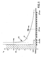
- Figure 5 shows a graph which establishes the voltage - actuation time ratio where it is possible to distinguish a zone (18) of non actuation of the switching device as opposed to another zone (19) of switching device actuation, and finally a curve (c) which establishes maximum limit of actuation time t A .
- the curve values (c ) shall vary according to the state of the art.
- Current international standards consider this maximum tolerance value to be adequate and therefore it is considered that all the connected loads should withstand this without problems for an indefinite period.
- the device could act or not, in the event that it did so it should be with a minimum delay time of 0.5 seconds to avoid tripping. It is considered that within this voltage margin damage to customary loads should not occur either. This margin permits a small tolerance in the actuation voltage, which on one hand does not damage the loads and on the other facilitates the fact that precision components or adjustments which would increase the price of the device are not required.
- the device For values between 15-20 % of the nominal voltage (265-275 V) the device has to act, in the event that it did so it should be with a minimum delay time of 0.5 seconds to avoid tripping, with the maximum value being that indicated in the c curve.
- FIG. 6 shows a diagram of the device in the event of actuation on an under-voltage release type.
- an electromechanical relay R L is used as actuator, and through its normally closed contact in order to adapt the functioning to an under-voltage release.
- the under-voltage release causes the actuation of the switching device when its supply voltage is lower than a specific limit, customarily between 50 to 70 % of its nominal voltage.
- the functioning of the combined device when there is a correct input voltage is such that the R L relay is not activated, the normally closed contact (terminals 11-12) remains in its resting position and the under-voltage release receives voltage, permitting the cut off device to be connecting and thus supply voltage reaches the installation and loads downstream.
- the input voltage exceeds the predetermined levels and times the relay acts opening the contact, this leaves the under-voltage release without voltage and causes opening of the switching device leaving the combined device and the installation without supply in order to protect it.
- under-voltage release introduces an added performance when the input voltage varies as the switching device will act not only through- overvoltage but also by under-voltage, this situation may represent both an advantage and a disadvantage depending on the planned use of the protection device. It may be an advantage as it adds a protection to loads which are sensitive to under-voltage, for example motors, refrigerators or air conditioning equipment, in contrast it may cause the cut off in the supply voltage due to micro cuts, prolonged gaps and drops in voltage.
- Figure 7 of the combined device which is the object of the invention for three-phase networks with configuration of the TT electrical network.
- a possible configuration may be that formed by the DG gas arrester (it limits - transient overvoltages between neutral and earth) the varistors V1,V2 and V3 (they limit transient overvoltages between lines and neutral) and the thermal fuses FT1, FT2 and FT3 which acts when each varistor reaches the end of its lifetime.
- the shunt release receives the L1'-N' voltage and opens the switching device, and consequently also all the devices and loads connected downstream of it (including the combined device they remain without supply and protected).
- the combined protection device for three-phase networks comprises :
- Figures 9 and 10 show the form of SD+ voltage in two of the possible extreme cases, this voltage will be used to obtain the trip signal.
- Figure 9 shows the case in which the three phases are at 265 V whereas figure 10 shows a case where only one phase is at 255 V.
- shunt release for functioning with continuous voltage, however, these have the disadvantage that their electrical characteristics largely depend on the manufacturers, and in order to resolve this disadvantage a trip signal with dephased bursts is used with a variable duty cycle in high frequency.
- the aim is to achieve a sequence of "n" impulses with an average value of growing voltage of one impulse to the next, so that in this way when the release trip voltage is reached this will act, causing the circuit-breaker to open and to cut off the supply voltage:
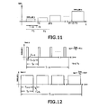
- Figure 11 shows a trip burst resulting from a sequence of impulses, in order to determine the duration of the impulses (T1) the typical release actuation times were taken into account, and therefore T1 duration impulses were considered adequate: 15 ... 25 ms.
- T1 duration impulses were considered adequate: 15 ... 25 ms.
- the impulses are dephased between each other a fixed time T1b, with a value lower than a half period (typical T1b: 3 ... 5 ms), in this way in some of the "n" impulses applied the voltage required to cause the trip will be achieved.
- V OUT2 signals indicated in figure 12 also show the conduction situation of the Q transistor ( figure 8 ):
- the release reacts to the average voltage value of the applied impulses, which depend on the conduction duty cycle of the transistor.
- the first impulse of the burst is preferably initiated with a reduced duty cycle of around (10%) and increases with every impulse until it reaches a maximum of around 90% , the number of impulses is generally restricted to a value between 10 and 15 in order to prevent voltage being permanently applied in the event of malfunctioning of the release.
- the device is also applicable in installations where protection against - transient overvoltages is not considered necessary. This situation is usually considered in applications where the electrical network is subterranean or above ground, however, in the geographical area considered there are few storms. It would therefore be a protection device only against temporary and permanent overvoltages.
- the cost of the device could be reduced by not using components designed to protect - transient overvoltages (in the electronic diagrams indicated above these would be the DG gas arresters and the V varistors).
- the essential nature of this invention is not altered by any variations in materials, form, size and arrangement of its component elements, which are described in a non-restrictive manner, with this being sufficient to proceed to its reproduction by an expert.
Landscapes
- Emergency Protection Circuit Devices (AREA)
Claims (17)
- Système de protection comprenant un dispositif combiné (3) de protection électrique à basse tension contre surtensions transitoires (3a) et contre surtensions transitoires et étendues (3b) fonctionnant en collaboration avec déclencheurs électromécaniques (2) causant l'ouverture d'un dispositif de commutation (1) lorsqu'il existe une surtension d'alimentation au-dessus d'un temps spécifique qui laisse des charges (5, 6) en aval du dispositif sans alimentation; le dispositif est muni d'une partie protégeant contre - surtensions transitoires (3a) et d'une autre partie protégeant contre surtensions transitoires et étendues (2b), dans lequel le dispositif de protection combiné- est disposé en aval du dispositif de commutation (1) sur lequel il agit et, donc, seulement est nécessaire qu'il résiste n'importe quelles surtensions transitoires ou étendues pouvant exister pendant le temps qui s'écoule depuis le début de la surtension jusqu'à l'ouverture de l'élément de commutation et il est séparé du réseau âpres son actionnement et l'ouverture du dispositif de commutation (1),- permet un temps d'actionnement depuis le début de la surtension jusqu'à l'ouverture de l'élément de commutation qui peut charger selon le niveau de surtension, et il est programmable pour éviter actions de déclenchement qui pourraient laisser, de façon pas nécessaire, à l'utilisateur sans service.
Etant caractérisé en ce que- il permet autant la valeur pic et la valeur rms du signal du réseau être traité de manière à produire le déclenchement et l'actionnement du dispositif de commutation (1).- Le déclencheur électromécanique reçoit un signal de déclenchement en accord avec une séquence d'impulsions ayant une valeur moyenne depuis une impulsion jusqu'à la prochaine ayant un temps de conduction croissant. - Système de protection selon la revendication 1, caractérisé en ce que la partie du dispositif qui protège contre surtensions transitoires et étendues pour un réseau monophasé est munie de- un fusible (7)- Une première source d'alimentation électrique (8) pour l'obtention d'une tension continue établie pour alimenter un contrôleur (16).- un filtre passe-bas à haute fréquence (9) disposé dans la sortie de la première source d'alimentation électrique (8).- Une deuxième source d'alimentation électrique (10) pour l'obtention d'une tension continue établie pour alimenter un actionneur (11).- Une commande (12) adaptant le signal de sortie du contrôleur (16) aux besoins de tension et de courant de l'actionneur (11).- Un atténuateur de tension (13) qui obtient dans son sortie un signal proportionnel à la tension du réseau, adapté à niveaux de tension admissibles pour le contrôleur (16).- Une protection contre surtensions transitoires ultra rapides (14) et un filtre passe-bas à haute fréquence (15).- Un témoin lumineux (12) qui s'active quand il existe de la surtension.- Un témoin lumineux (13) indiquant la présence de tension à l'entrée du dispositif combiné et le bon fonctionnement du contrôleur.
- Système de protection selon la revendication 2, caractérisé en ce que:- La première source d'alimentation électrique (8) se compose de:C1, R1: Impédance de limitation de courantD1: Diode redresseuseC2: Condensateur de filtrageDS 1: Diode suppresseur ayant une double fonction en plus de limiter la valeur des possibles surtensions transitoires ultra rapides, il agit aussi comme un stabilisateur de tension d'une manière similaire à une diode Zener.- Le filtre (9) étant connecté à la sortie de la première source d'alimentation électrique (8)
comprend:R2, C3: qui est un filtre passe-bas à haute fréquence.- la deuxième source d'alimentation électrique (10) se compose de:D2. Redresse la tension du réseau en demi-ondeZ1: Diode Zener pour réduire la valeur du signal pic du redresseur.R3: Limite le courant en circulation par la diode Z2.C4: Condensateur de filtrage permettant une tension continue à ondulation réduite.Z2: Diode Zener qui limite et établie la tension d'alimentation de l'actionneur.- L'atténuateur de tension (13) se composant de:R4, R5 et D3: les résistances réduisent la valeur de la tension de sortie du rupteur aux niveaux adéquats de l'entrée du contrôleur. La diode D3 élimine la partie négative du signal alternatif.- la partie protégeant contre surtensions transitoires ultra rapides (14) comprend DS2 qui est une diode suppresseur pour surtensions transitoires ultra rapides.- Le filtre passe-bas à haute fréquence (15) se compose de R6, R7 et C5 et il s'utilise pour les mêmes raisons que dans le cas de la source d'alimentation électrique 1. - Système de protection selon la revendication 2 caractérisé en ce que la commande (12) et l'indication d'activation se composent d'un transistor Q, quand la sortie OUT 2 du contrôleur adopte un niveau haut, il permet la circulation du courant par le témoin lumineux (12) el par l'actionneur RL (11), produisant un signal de déclenchement qui actionne le déclencheur électromécanique, la commande (12) est aussi muni d'une résistance R8 avec une taille telle que avec un niveau haut dans la sortie OUT 2 du contrôleur (16) on fournie un courant de base au transistor Q qui est suffisant pour la conduction.
- Système de protection selon la revendication 2, caractérisé en ce que l'indication de fonctionnement (17) se compose de: R9, I3:
- Système de protection selon la revendication 4, caractérisé en ce que l'actionneur (11) est un relais électromécanique.
- Système de protection selon la revendication 4, caractérisé en ce que les actionneurs (11) sont dispositifs en état solide tels que triacs et thyristors.
- Système de protection selon la revendication 1, caractérisé en ce que pour des réseaux triphasés le dispositif de protection combiné pour réseaux triphasés se compose d'une partie protégeant contre - surtensions transitoires et une autre partie protégeant contre surtensions transitoires et étendues comprenant- un redressement d'entrée et étage de protection (20),- une première source d'alimentation électrique (21) du contrôleur (23),- un filtre passe-bas à haute fréquence (22) en collaboration avec ladite source d'alimentation électrique (21)- un atténuateur de tension (24)- un filtre passe-bas à haute fréquence (25) en collaboration avec ledit atténuateur dans son sortie.- un contrôleur (23)- un indicateur de fonctionnement (26),- un actionneur (28)- une commande (27) et indication d'activation (12)
- Système de protection selon la revendication, 8 caractérisé en ce que le redressement et l'étage de protection d'entrée (20) se compose de:D1, D2, D3: Elles agissent comme redresseur triphasé de la tension du réseau.D4: elle protège les impulsions de courant du potentiel zéro.PTC: il s'utilise comme un dispositif de protection d'entrée au lieu de un fusible, étant donné qu'il évite que les pics de courant circulant par le déclencheur shunt lui endommagent malgré son bon fonctionnement.
- Système de protection selon les revendications 1 à 8, caractérisé en ce que le contrôleur est muni d'une entrée avec un convertisseur analog/numérique de façon qu'il puisse obtenir l'information complète sur les plus importants des paramètres de tension d'entrée de manière à produire le déclenchement: Durée de la surtension, valeur rms (Vrms) et valeur pic (Vpk), depuis que la tension d'entrée surpasse les niveaux de tension et temps prédéterminés, le contrôleur génère dans sa sortie OUT 2 un signal adéquat de manière à déclencher le déclencheur électromécanique, et le dispositif est également adéquat pour réaliser la programmation en circuit.
- Système de protection selon la revendication 8, caractérisé en ce que l'actionneur (28) se compose d'un transistor Q du type MOSFET, contrôlé par sa tension de grille et en plus il est muni de.
R7: on l'utilise pour éviter oscillations quand le photo-transistor de l'optocoupleur O1 est coupé, en évitant ainsi le déclenchement indésirable.
V4, D5: Le transistor agit sur une charge inductive et, donc, quand le flux de courant s'interrompe, des surtensions sont créés, et afin d'éviter qu'elles affectent au transistor, celles-ci sont limitées par l'intermédiaire de une varistance V4 et une diode D5. - Système de protection selon la revendication 8, caractérisé en ce que la commande (27) se compose de une photo-diode O1, une résistance R6 et un indicateur d'activation I2 de façon à ce que quand on détecte une surtension transitoire ou étendue qui surpasse valeurs et temps prédéterminées, la tension de sortie OUT 2 du contrôleur adopte niveaux hauts, circulant courant par la photo diode 01, R6 et l'indicateur d'activation 12, causant la saturation du phototransistor O1 et on applique une tension qui est environ égal à la tension de la diode Zener DZI à la grille du transistor Q, en atteignant ainsi sa conduction et actionnement du déclencheur, où la tension de Zener est obtenue sur la base de la tension triphasée redressée SD+, par l'intermédiaire de R5 et DZI, donc même dans le cas où deux parmi les trois phases se perdent, on fourni tension pour agir sur le transistor Q et sur le déclencheur shunt.
- Système de protection selon la revendication 12, caractérisé en ce que la séquence d'impulsion reçue par les déclencheurs électromécaniques présente un cycle de fonctionnement réduit d'environ (10%) et augmentations à chaque impulsion jusqu'à il atteint un maximum d'environ (90%).
- Système de protection selon la revendication 1, caractérisé en ce que le temps d'actionnement variable et programmable qui évite un déclenchement indésirable se compose d'une zone (18) sans actionnement du dispositif de commutation, par opposition à une autre zone (19) d'activation du dispositif de commutation, où les temps de la zone sans actionnement sont inferieurs à une courbe qui établie le limite maximum du temps d'actionnement tA et qui change selon l'état de la technique.
- Système de protection selon la revendication 10, caractérisé en ce que le déclencheur électromécanique collaborant avec le dispositif de commutation est un déclencheur shunt.
- Système de protection selon la revendication 10, caractérisé en ce que le déclencheur électromécanique collaborant avec le dispositif de commutation est un déclencheur à minimum de tension agissant ne seulement dans le cas de surtension mais aussi dans sub-tension.
- Système de protection selon la revendication 8, caractérisé en ce que le déclencheur shunt du commutateur électromécanique se déclenche même dans le cas où la tension d'une ou deux phases se perdre et, donc, le signal de déclenchement se génère à partir du signal triphasé.
Priority Applications (4)
| Application Number | Priority Date | Filing Date | Title |
|---|---|---|---|
| DE602008001972T DE602008001972D1 (de) | 2008-05-29 | 2008-05-29 | Kombinierte elektrische Schutzvorrichtung gegen transiente, zeitliche und verbreitete Überspannungen |
| EP08381019A EP2131468B1 (fr) | 2008-05-29 | 2008-05-29 | Dispositif combiné de protection électrique contre les surtensions transitoires et étendues |
| ES08381019T ES2350025T3 (es) | 2008-05-29 | 2008-05-29 | Dispositivo combinado de protección eléctrica contra sobretensiones transitorias, temporales y permanentes. |
| AT08381019T ATE476005T1 (de) | 2008-05-29 | 2008-05-29 | Kombinierte elektrische schutzvorrichtung gegen transiente, zeitliche und verbreitete überspannungen |
Applications Claiming Priority (1)
| Application Number | Priority Date | Filing Date | Title |
|---|---|---|---|
| EP08381019A EP2131468B1 (fr) | 2008-05-29 | 2008-05-29 | Dispositif combiné de protection électrique contre les surtensions transitoires et étendues |
Publications (2)
| Publication Number | Publication Date |
|---|---|
| EP2131468A1 EP2131468A1 (fr) | 2009-12-09 |
| EP2131468B1 true EP2131468B1 (fr) | 2010-07-28 |
Family
ID=39869737
Family Applications (1)
| Application Number | Title | Priority Date | Filing Date |
|---|---|---|---|
| EP08381019A Active EP2131468B1 (fr) | 2008-05-29 | 2008-05-29 | Dispositif combiné de protection électrique contre les surtensions transitoires et étendues |
Country Status (4)
| Country | Link |
|---|---|
| EP (1) | EP2131468B1 (fr) |
| AT (1) | ATE476005T1 (fr) |
| DE (1) | DE602008001972D1 (fr) |
| ES (1) | ES2350025T3 (fr) |
Families Citing this family (2)
| Publication number | Priority date | Publication date | Assignee | Title |
|---|---|---|---|---|
| EP3422142B1 (fr) * | 2017-06-30 | 2021-07-14 | duagon AG | Procédé pour fournir de l'énergie électrique à une carte d'interface et contrôleur d'état de sécurité |
| CN121035716B (zh) * | 2025-10-29 | 2026-02-27 | 珠海市钛芯动力科技股份有限公司 | 一种防雷插座 |
Family Cites Families (5)
| Publication number | Priority date | Publication date | Assignee | Title |
|---|---|---|---|---|
| US5450029A (en) * | 1993-06-25 | 1995-09-12 | At&T Corp. | Circuit for estimating a peak or RMS value of a sinusoidal voltage waveform |
| ES2170671B1 (es) | 2000-06-20 | 2003-09-16 | Gordon Salvador Romero | Dispositivo electronico de proteccion electrica en baja tension frente a sobretensiones en el punto de suministro particular. |
| DE10243858A1 (de) * | 2002-09-20 | 2004-04-01 | Siemens Ag | Netzüberspannungsschutz |
| AR042973A1 (es) * | 2004-01-29 | 2005-07-13 | Tyco Electronics Argentina S A | Dispositivo protector contra sobretensiones en lineas telefonicas y/o de datos,apto para instalaciones con puesta a tierra de mala calidad, y metodo para proteger una linea telefonica y/o de datos. |
| ES2368922T3 (es) | 2005-03-08 | 2011-11-23 | Cirprotec, S.L. | Dispositivo combinado de protección eléctrica a baja tensión contra sobretensiones transitorias y prolongadas con reconexión automática. |
-
2008
- 2008-05-29 EP EP08381019A patent/EP2131468B1/fr active Active
- 2008-05-29 DE DE602008001972T patent/DE602008001972D1/de active Active
- 2008-05-29 ES ES08381019T patent/ES2350025T3/es active Active
- 2008-05-29 AT AT08381019T patent/ATE476005T1/de not_active IP Right Cessation
Also Published As
| Publication number | Publication date |
|---|---|
| ES2350025T3 (es) | 2011-01-17 |
| ATE476005T1 (de) | 2010-08-15 |
| DE602008001972D1 (de) | 2010-09-09 |
| EP2131468A1 (fr) | 2009-12-09 |
Similar Documents
| Publication | Publication Date | Title |
|---|---|---|
| US7245470B2 (en) | Unsafe voltage shutoff control | |
| EP3770936B1 (fr) | Disjoncteur hybride à entrefer/semi-conducteur | |
| CA2833384C (fr) | Correcteur de chute de tension utilisant un convertisseur-amplificateur a cycle de service variable | |
| EP1847001B1 (fr) | Limiteurs actifs de pic de courant | |
| CN102315630B (zh) | 家庭用烹调设备 | |
| WO2006074111A2 (fr) | Detection d'un courant de fuite et circuit d'interruption | |
| US12074591B2 (en) | Method for actuating a semiconductor power switch, actuation circuit for a semiconductor power switch, and electronic circuit breaker | |
| SK282610B6 (sk) | Ochranné zapojenie na usporiadanie zvodu prepätia | |
| CN110268493B (zh) | 低电压保护开关单元 | |
| US12562322B2 (en) | Circuit breaker | |
| SK18498A3 (en) | Disconnector for surge arrester | |
| US20240395480A1 (en) | Circuit breaker and method | |
| KR101622187B1 (ko) | 한류기 | |
| EP2131468B1 (fr) | Dispositif combiné de protection électrique contre les surtensions transitoires et étendues | |
| KR200312397Y1 (ko) | 자동복귀형 누전차단기 | |
| EP1701424B1 (fr) | Dispositif combiné de protection electrique a baisse tension contre les sur-tensions transitoires et etendue avec reconnexion automatique | |
| CN109075559B (zh) | 用于保护连接在多相网络上的用电器的具有低压和过压切断功能的电路布置系统 | |
| CN110912101A (zh) | 一种非接触无源式spd后备保护断路器 | |
| RU2619777C2 (ru) | Устройство защиты электрических потребителей от перенапряжений в однофазных сетях переменного тока | |
| US6788515B1 (en) | Over-current control | |
| JPH11299082A (ja) | 過電圧保護機能付き漏電遮断装置 | |
| Gurevich | RCD nuisance tripping: who’s guilty and what needs to be done? | |
| RU2241294C2 (ru) | Устройство кужекова-крыночкина защиты электроприемников от превышения напряжения | |
| KR860001479B1 (ko) | 배전선로 고장구간 자동 개방 차단 장치 | |
| HK40035799B (en) | Hybrid air-gap/solid-state circuit breaker |
Legal Events
| Date | Code | Title | Description |
|---|---|---|---|
| PUAI | Public reference made under article 153(3) epc to a published international application that has entered the european phase |
Free format text: ORIGINAL CODE: 0009012 |
|
| 17P | Request for examination filed |
Effective date: 20090903 |
|
| AK | Designated contracting states |
Kind code of ref document: A1 Designated state(s): AT BE BG CH CY CZ DE DK EE ES FI FR GB GR HR HU IE IS IT LI LT LU LV MC MT NL NO PL PT RO SE SI SK TR |
|
| AX | Request for extension of the european patent |
Extension state: AL BA MK RS |
|
| GRAP | Despatch of communication of intention to grant a patent |
Free format text: ORIGINAL CODE: EPIDOSNIGR1 |
|
| GRAS | Grant fee paid |
Free format text: ORIGINAL CODE: EPIDOSNIGR3 |
|
| GRAA | (expected) grant |
Free format text: ORIGINAL CODE: 0009210 |
|
| AK | Designated contracting states |
Kind code of ref document: B1 Designated state(s): AT BE BG CH CY CZ DE DK EE ES FI FR GB GR HR HU IE IS IT LI LT LU LV MC MT NL NO PL PT RO SE SI SK TR |
|
| REG | Reference to a national code |
Ref country code: GB Ref legal event code: FG4D |
|
| REG | Reference to a national code |
Ref country code: CH Ref legal event code: EP |
|
| AKX | Designation fees paid |
Designated state(s): AT BE BG CH CY CZ DE DK EE ES FI FR GB GR HR HU IE IS IT LI LT LU LV MC MT NL NO PL PT RO SE SI SK TR |
|
| REG | Reference to a national code |
Ref country code: IE Ref legal event code: FG4D |
|
| REF | Corresponds to: |
Ref document number: 602008001972 Country of ref document: DE Date of ref document: 20100909 Kind code of ref document: P |
|
| REG | Reference to a national code |
Ref country code: NL Ref legal event code: VDEP Effective date: 20100728 |
|
| LTIE | Lt: invalidation of european patent or patent extension |
Effective date: 20100728 |
|
| REG | Reference to a national code |
Ref country code: ES Ref legal event code: FG2A Effective date: 20110104 |
|
| PG25 | Lapsed in a contracting state [announced via postgrant information from national office to epo] |
Ref country code: LT Free format text: LAPSE BECAUSE OF FAILURE TO SUBMIT A TRANSLATION OF THE DESCRIPTION OR TO PAY THE FEE WITHIN THE PRESCRIBED TIME-LIMIT Effective date: 20100728 Ref country code: NO Free format text: LAPSE BECAUSE OF FAILURE TO SUBMIT A TRANSLATION OF THE DESCRIPTION OR TO PAY THE FEE WITHIN THE PRESCRIBED TIME-LIMIT Effective date: 20101028 Ref country code: FI Free format text: LAPSE BECAUSE OF FAILURE TO SUBMIT A TRANSLATION OF THE DESCRIPTION OR TO PAY THE FEE WITHIN THE PRESCRIBED TIME-LIMIT Effective date: 20100728 Ref country code: AT Free format text: LAPSE BECAUSE OF FAILURE TO SUBMIT A TRANSLATION OF THE DESCRIPTION OR TO PAY THE FEE WITHIN THE PRESCRIBED TIME-LIMIT Effective date: 20100728 Ref country code: NL Free format text: LAPSE BECAUSE OF FAILURE TO SUBMIT A TRANSLATION OF THE DESCRIPTION OR TO PAY THE FEE WITHIN THE PRESCRIBED TIME-LIMIT Effective date: 20100728 |
|
| PG25 | Lapsed in a contracting state [announced via postgrant information from national office to epo] |
Ref country code: PL Free format text: LAPSE BECAUSE OF FAILURE TO SUBMIT A TRANSLATION OF THE DESCRIPTION OR TO PAY THE FEE WITHIN THE PRESCRIBED TIME-LIMIT Effective date: 20100728 Ref country code: IS Free format text: LAPSE BECAUSE OF FAILURE TO SUBMIT A TRANSLATION OF THE DESCRIPTION OR TO PAY THE FEE WITHIN THE PRESCRIBED TIME-LIMIT Effective date: 20101128 Ref country code: HR Free format text: LAPSE BECAUSE OF FAILURE TO SUBMIT A TRANSLATION OF THE DESCRIPTION OR TO PAY THE FEE WITHIN THE PRESCRIBED TIME-LIMIT Effective date: 20100728 Ref country code: BG Free format text: LAPSE BECAUSE OF FAILURE TO SUBMIT A TRANSLATION OF THE DESCRIPTION OR TO PAY THE FEE WITHIN THE PRESCRIBED TIME-LIMIT Effective date: 20101028 Ref country code: CY Free format text: LAPSE BECAUSE OF FAILURE TO SUBMIT A TRANSLATION OF THE DESCRIPTION OR TO PAY THE FEE WITHIN THE PRESCRIBED TIME-LIMIT Effective date: 20100728 Ref country code: SI Free format text: LAPSE BECAUSE OF FAILURE TO SUBMIT A TRANSLATION OF THE DESCRIPTION OR TO PAY THE FEE WITHIN THE PRESCRIBED TIME-LIMIT Effective date: 20100728 |
|
| PG25 | Lapsed in a contracting state [announced via postgrant information from national office to epo] |
Ref country code: LV Free format text: LAPSE BECAUSE OF FAILURE TO SUBMIT A TRANSLATION OF THE DESCRIPTION OR TO PAY THE FEE WITHIN THE PRESCRIBED TIME-LIMIT Effective date: 20100728 Ref country code: BE Free format text: LAPSE BECAUSE OF FAILURE TO SUBMIT A TRANSLATION OF THE DESCRIPTION OR TO PAY THE FEE WITHIN THE PRESCRIBED TIME-LIMIT Effective date: 20100728 Ref country code: SE Free format text: LAPSE BECAUSE OF FAILURE TO SUBMIT A TRANSLATION OF THE DESCRIPTION OR TO PAY THE FEE WITHIN THE PRESCRIBED TIME-LIMIT Effective date: 20100728 Ref country code: GR Free format text: LAPSE BECAUSE OF FAILURE TO SUBMIT A TRANSLATION OF THE DESCRIPTION OR TO PAY THE FEE WITHIN THE PRESCRIBED TIME-LIMIT Effective date: 20101029 |
|
| PG25 | Lapsed in a contracting state [announced via postgrant information from national office to epo] |
Ref country code: DK Free format text: LAPSE BECAUSE OF FAILURE TO SUBMIT A TRANSLATION OF THE DESCRIPTION OR TO PAY THE FEE WITHIN THE PRESCRIBED TIME-LIMIT Effective date: 20100728 |
|
| PG25 | Lapsed in a contracting state [announced via postgrant information from national office to epo] |
Ref country code: CZ Free format text: LAPSE BECAUSE OF FAILURE TO SUBMIT A TRANSLATION OF THE DESCRIPTION OR TO PAY THE FEE WITHIN THE PRESCRIBED TIME-LIMIT Effective date: 20100728 Ref country code: EE Free format text: LAPSE BECAUSE OF FAILURE TO SUBMIT A TRANSLATION OF THE DESCRIPTION OR TO PAY THE FEE WITHIN THE PRESCRIBED TIME-LIMIT Effective date: 20100728 Ref country code: SK Free format text: LAPSE BECAUSE OF FAILURE TO SUBMIT A TRANSLATION OF THE DESCRIPTION OR TO PAY THE FEE WITHIN THE PRESCRIBED TIME-LIMIT Effective date: 20100728 Ref country code: IT Free format text: LAPSE BECAUSE OF FAILURE TO SUBMIT A TRANSLATION OF THE DESCRIPTION OR TO PAY THE FEE WITHIN THE PRESCRIBED TIME-LIMIT Effective date: 20100728 Ref country code: RO Free format text: LAPSE BECAUSE OF FAILURE TO SUBMIT A TRANSLATION OF THE DESCRIPTION OR TO PAY THE FEE WITHIN THE PRESCRIBED TIME-LIMIT Effective date: 20100728 |
|
| PLBE | No opposition filed within time limit |
Free format text: ORIGINAL CODE: 0009261 |
|
| STAA | Information on the status of an ep patent application or granted ep patent |
Free format text: STATUS: NO OPPOSITION FILED WITHIN TIME LIMIT |
|
| 26N | No opposition filed |
Effective date: 20110429 |
|
| REG | Reference to a national code |
Ref country code: DE Ref legal event code: R097 Ref document number: 602008001972 Country of ref document: DE Effective date: 20110429 |
|
| PG25 | Lapsed in a contracting state [announced via postgrant information from national office to epo] |
Ref country code: MT Free format text: LAPSE BECAUSE OF FAILURE TO SUBMIT A TRANSLATION OF THE DESCRIPTION OR TO PAY THE FEE WITHIN THE PRESCRIBED TIME-LIMIT Effective date: 20100728 Ref country code: MC Free format text: LAPSE BECAUSE OF NON-PAYMENT OF DUE FEES Effective date: 20110531 |
|
| REG | Reference to a national code |
Ref country code: IE Ref legal event code: MM4A |
|
| PG25 | Lapsed in a contracting state [announced via postgrant information from national office to epo] |
Ref country code: IE Free format text: LAPSE BECAUSE OF NON-PAYMENT OF DUE FEES Effective date: 20110529 |
|
| REG | Reference to a national code |
Ref country code: CH Ref legal event code: PL |
|
| PG25 | Lapsed in a contracting state [announced via postgrant information from national office to epo] |
Ref country code: LI Free format text: LAPSE BECAUSE OF NON-PAYMENT OF DUE FEES Effective date: 20120531 Ref country code: CH Free format text: LAPSE BECAUSE OF NON-PAYMENT OF DUE FEES Effective date: 20120531 |
|
| PG25 | Lapsed in a contracting state [announced via postgrant information from national office to epo] |
Ref country code: LU Free format text: LAPSE BECAUSE OF NON-PAYMENT OF DUE FEES Effective date: 20110529 |
|
| PG25 | Lapsed in a contracting state [announced via postgrant information from national office to epo] |
Ref country code: PT Free format text: LAPSE BECAUSE OF NON-PAYMENT OF DUE FEES Effective date: 20100728 |
|
| PG25 | Lapsed in a contracting state [announced via postgrant information from national office to epo] |
Ref country code: TR Free format text: LAPSE BECAUSE OF FAILURE TO SUBMIT A TRANSLATION OF THE DESCRIPTION OR TO PAY THE FEE WITHIN THE PRESCRIBED TIME-LIMIT Effective date: 20100728 |
|
| PG25 | Lapsed in a contracting state [announced via postgrant information from national office to epo] |
Ref country code: HU Free format text: LAPSE BECAUSE OF FAILURE TO SUBMIT A TRANSLATION OF THE DESCRIPTION OR TO PAY THE FEE WITHIN THE PRESCRIBED TIME-LIMIT Effective date: 20100728 |
|
| REG | Reference to a national code |
Ref country code: FR Ref legal event code: PLFP Year of fee payment: 8 |
|
| REG | Reference to a national code |
Ref country code: FR Ref legal event code: PLFP Year of fee payment: 9 |
|
| REG | Reference to a national code |
Ref country code: FR Ref legal event code: PLFP Year of fee payment: 10 |
|
| REG | Reference to a national code |
Ref country code: FR Ref legal event code: PLFP Year of fee payment: 11 |
|
| PGFP | Annual fee paid to national office [announced via postgrant information from national office to epo] |
Ref country code: IT Payment date: 20190527 Year of fee payment: 10 |
|
| PGFP | Annual fee paid to national office [announced via postgrant information from national office to epo] |
Ref country code: FR Payment date: 20190529 Year of fee payment: 12 |
|
| PGFP | Annual fee paid to national office [announced via postgrant information from national office to epo] |
Ref country code: GB Payment date: 20190423 Year of fee payment: 12 |
|
| REG | Reference to a national code |
Ref country code: DE Ref legal event code: R119 Ref document number: 602008001972 Country of ref document: DE |
|
| GBPC | Gb: european patent ceased through non-payment of renewal fee |
Effective date: 20200529 |
|
| PG25 | Lapsed in a contracting state [announced via postgrant information from national office to epo] |
Ref country code: FR Free format text: LAPSE BECAUSE OF NON-PAYMENT OF DUE FEES Effective date: 20200531 Ref country code: GB Free format text: LAPSE BECAUSE OF NON-PAYMENT OF DUE FEES Effective date: 20200529 |
|
| PG25 | Lapsed in a contracting state [announced via postgrant information from national office to epo] |
Ref country code: DE Free format text: LAPSE BECAUSE OF NON-PAYMENT OF DUE FEES Effective date: 20201201 |
|
| PGFP | Annual fee paid to national office [announced via postgrant information from national office to epo] |
Ref country code: ES Payment date: 20250807 Year of fee payment: 18 |