EP2132117B1 - Procédé et circuit de commande permettant de régler un interstice - Google Patents
Procédé et circuit de commande permettant de régler un interstice Download PDFInfo
- Publication number
- EP2132117B1 EP2132117B1 EP08735065.8A EP08735065A EP2132117B1 EP 2132117 B1 EP2132117 B1 EP 2132117B1 EP 08735065 A EP08735065 A EP 08735065A EP 2132117 B1 EP2132117 B1 EP 2132117B1
- Authority
- EP
- European Patent Office
- Prior art keywords
- gap
- material surface
- product
- gap width
- predetermined
- Prior art date
- Legal status (The legal status is an assumption and is not a legal conclusion. Google has not performed a legal analysis and makes no representation as to the accuracy of the status listed.)
- Active
Links
Images


Classifications
-
- B—PERFORMING OPERATIONS; TRANSPORTING
- B65—CONVEYING; PACKING; STORING; HANDLING THIN OR FILAMENTARY MATERIAL
- B65H—HANDLING THIN OR FILAMENTARY MATERIAL, e.g. SHEETS, WEBS, CABLES
- B65H3/00—Separating articles from piles
- B65H3/46—Supplementary devices or measures to assist separation or prevent double feed
- B65H3/52—Friction retainers acting on under or rear side of article being separated
- B65H3/5246—Driven retainers, i.e. the motion thereof being provided by a dedicated drive
-
- B—PERFORMING OPERATIONS; TRANSPORTING
- B65—CONVEYING; PACKING; STORING; HANDLING THIN OR FILAMENTARY MATERIAL
- B65H—HANDLING THIN OR FILAMENTARY MATERIAL, e.g. SHEETS, WEBS, CABLES
- B65H2511/00—Dimensions; Position; Numbers; Identification; Occurrences
- B65H2511/10—Size; Dimensions
- B65H2511/13—Thickness
-
- B—PERFORMING OPERATIONS; TRANSPORTING
- B65—CONVEYING; PACKING; STORING; HANDLING THIN OR FILAMENTARY MATERIAL
- B65H—HANDLING THIN OR FILAMENTARY MATERIAL, e.g. SHEETS, WEBS, CABLES
- B65H2515/00—Physical entities not provided for in groups B65H2511/00 or B65H2513/00
- B65H2515/30—Forces; Stresses
- B65H2515/32—Torque e.g. braking torque
-
- B—PERFORMING OPERATIONS; TRANSPORTING
- B65—CONVEYING; PACKING; STORING; HANDLING THIN OR FILAMENTARY MATERIAL
- B65H—HANDLING THIN OR FILAMENTARY MATERIAL, e.g. SHEETS, WEBS, CABLES
- B65H2557/00—Means for control not provided for in groups B65H2551/00 - B65H2555/00
- B65H2557/60—Details of processes or procedures
- B65H2557/61—Details of processes or procedures for calibrating
-
- B—PERFORMING OPERATIONS; TRANSPORTING
- B65—CONVEYING; PACKING; STORING; HANDLING THIN OR FILAMENTARY MATERIAL
- B65H—HANDLING THIN OR FILAMENTARY MATERIAL, e.g. SHEETS, WEBS, CABLES
- B65H2801/00—Application field
- B65H2801/66—Envelope filling machines
Definitions
- the invention relates to a method and a control circuit for setting a gap, in particular a gap, through which a good is conveyed.
- Paper handling systems such as Inserting systems include applications where a stack of goods, e.g. Leaves or envelopes, one sheet or envelope for processing in the system is provided.
- Such systems include, for example, slip feeders or envelope feeders, but also folding units, which are provided with goods from a stack individually or in groups from a stack.
- the EP 0 776 845 A1 describes a lock for paper sheets which can be adjusted to different material thicknesses.
- De lock comprises between a continuously rotating during operation friction roller and a radially adjustable with respect to the friction roller, paraxial brake roller a passage gap.
- An electrical switching element outputs a control signal for an electrical circuit when setting the passage gap to a certain thickness of a pattern located in the passage gap.
- the brake roller is rotatably mounted on the cylindrical eccentric driven by a first electric motor drive, optionally in both directions adjustable eccentric shaft and stationary stationary friction roller by a second electric motor drive with respect to the adjustment of the brake roller substantially higher rotational speed, via a movable from its normal position Transmission part drivable.
- the present invention has for its object to enable a positive effect on the processing impacting, precise and reproducible lock adjustment with respect to the pull-out force.
- Fig. 1 shows a supplement feeder comprising a transport belt 100 which is guided around a suction drum 102 and about other guide rollers 104, 106 and 108.
- the transport belt 100 is driven in the conveying direction A.
- two fixed lock rollers 110a and 110b are provided, which are arranged between the suction drum 102 and the guide roller 104 such that the transport belt 100 is also moved over the lock rollers.
- the lock rollers 110a and 110b are attached to a holder 112.
- the installer feeder includes a controller 120 which controls the operation of the insert feeder.
- the controller 120 is connected to a servo motor 122 for moving a chassis 124, as indicated by the arrow 126.
- a chassis or support 124 of the lock counter-rotating belt 128 is arranged, which is guided over a plurality of guide rollers 130 to 138 and against the conveying direction A is driven (preferably clocked).
- the chassis 124 and thus the mating belt 128 is arranged such that the guide roller 130 is arranged via a hook-shaped projection on the chassis 124 opposite to the lock rollers 110a and 110b and opposite to the transport belt 100.
- a gap 140 (also referred to as a lock gap) is defined adjustable by the distance between the transport belt 100 and the lock rollers 110a, 110b and the counter-rotating belt 128.
- the servo motor 122 causes a lateral movement of the chassis 124 and thus the counter-rotating belt 128, whereby the gap 140, so the distance between the rollers can be adjusted.
- the supplement feeder further comprises a baffle 142 and a counter roll 144 for advancing a product after singulation in a desired direction.
- a crop receptacle 145 for receiving a stack of goods 146 for example a sheet or paper stack
- a crop receptacle 145 for receiving a stack of goods 146, for example a sheet or paper stack, is provided, in the Fig. 1 is shown schematically and from which the individual goods 148 are deducted.
- the goods 148 are arranged standing in the stack 146 (standing on one of the edges) and rest against a stop 150.
- the goods 148 facing surface of the stopper 150 is flush with the belt 100 in a forward direction A region, wherein the suction drum and the transport belt 100 cooperate to suck the foremost material of the stack 146 and to move in the conveying direction A. If the gap 140 is set correctly, only a single good is allowed through. A possibly double-deducted good, so another deducted Good is retained due to the small width and working counter to the direction of counter-belt 128.
- the crop receptacle 145 further includes a guide member 152 extending to the gap 140 through which the goods are dispensed.
- the guide element 152 for example a guide plate, can also have other shapes.
- the guide element 152 may, for example, have a rounding in the region of the gap 140 in order to guide the goods in the direction of the gap 140 and to the guide roller 130.
- the goods receptacle 145 For feeding the goods to the stop 150, the goods receptacle 145 comprises a goods transport 154, which comprises two parallel belts 154a and 154b, which convey the introduced goods standing in the direction of the stop 150.
- the Guttransport 154 further includes a rear, movable stopper 154c, which holds the goods introduced.
- the belts 154a and 154b are arranged in a bottom plate 156 of the Gutfact 145.
- a sheet feeder comprises a separating lock, which includes, for example, a first transport belt which runs around at least one suction drum to withdraw individual goods from a stack in a conveying direction. Further, a lock mating belt provided, which is driven in a direction opposite to the conveying direction of the goods and cooperates with the transport belt to form the separating lock. More specifically, the transport belt and the lock mating belt are arranged to each other such that the lock gap is set therebetween. The distance between the transport belt and the lock mating belt is chosen so that when a deduction of a good from the stack only the withdrawn Good is moved through the lock gap. Other goods that may also be deducted will be withheld.
- the transport belt used also transport or counter-rotating rollers can be used.
- the functionality is similar both when using belts and when using rollers or a combination of roller and belt.
- a user will manually adjust the lock gap before beginning the singulation to a suitable width for the material to be processed. It must be ensured that the width is chosen so that on the one hand double deductions, ie the simultaneous deduction of two or more goods, and on the other a "non-deduction" of goods safely avoided.
- the transport belt or the transport rollers are arranged, for example, fixed, whereas the counter-rotating or counter-rotating rollers are arranged movable (displaceable) so as to be able to adjust the lock gap to the required width for the material to be processed by a corresponding displacement of the mating device.
- This setting requires at least the user input regarding the thickness of the material to be processed.
- the lock gap is then adjusted by moving the mating belt. Further, in the setting of the gap, the restraining force of the between Transport unit and the retaining element clamped Guts to be observed during transport through the lock.
- the lock adjustment of the pull-out force (restraint force of the goods clamped between the transfer unit and the counter-holding member when transported through the lock) is made manually on the basis of the personal "feeling" or manually with a measuring or adjusting instrument, e.g. a spring balance. In order to enable the withdrawal process, the lock adjustment is realized so that the pull-out force is less than a possible withdrawal force.
- a measuring or adjusting instrument e.g. a spring balance.
- Embodiments of the present invention allow adjustment of the lock pull-out force side-by-side and material-independent.
- the setting can be done fully automatically without user intervention according to the following method.
- the supplement is placed in the feeder and at the lock.
- the lock is then opened by, for example, the transport unit and the holding unit are moved apart relative to each other.
- the supplement is inserted into the open lock and stopped in the lock.
- the retaining element for example the counter-rotating roller, is acted upon by a specific torque in order to drive it against the conveying direction.
- the predetermined torque which was applied to the counter-rotating roller, for example, corresponds to the amount of injected current in a flanged stepper motor.
- the angry Torque is proportional to the injected current and can be adjusted accordingly by this.
- the lock is closed by an automatic feed of the retaining element until the retaining element stops due to the applied force.
- the applied force results from the friction force resulting from the applied normal force and the coefficient of friction on the side surface of the insert. If the retaining element stops due to the applied force, the lock can be closed even further. Alternatively, decreasing the nip width may be stopped as soon as the restraining element stops due to the applied force.
- the closing of the lock can be realized in small steps.
- the engine may be coupled to the rotatable member via a mechanical transmission, wherein the mechanical transmission is dimensioned in response to a desired restraining force in the gap to adjust the predetermined torque. Since at a constant drive torque, which is defined by the introduced current, the force is always the same, which counteracts the torque at the time of standstill, the restraining force applied in this method is also always the same size.
- the now found Lock setting corresponds to a pull-out force that is proportional to the torque applied by the injected current.
- the pull-out force can be adjusted by this method, regardless of material always the same and constant to a level below the withdrawal force. Since this value is significant and characteristic element of a reliable functionality, a simple and reliable setting is possible by the described method.
- the retaining element In production, the retaining element is subject to ongoing wear, so that this also change the conditions in the air gap and thus the pull-out force.
- the correction of these conditions in the event of a fault and the compensation of wear, which was traditionally done manually only when needed, are now possible by the method according to embodiments of the invention fully automatically and at regular times.
- Embodiments of the invention therefore allow the detection of wear of the retaining element by the change in the lock gap (distance between the transport element and the retaining element) is determined, and possibly also compared with the measured thickness of the goods.
- the currently prevailing frictional force can be determined. Possible deviations from an initial state can also be indexed, for example, by increasingly occurring false or double prints.
- corrective measures can be taken, such as, for example, a readjustment of the pull-out force or of the lock gap.
- Embodiments of the invention optimize the process so that it takes only about 25 seconds, whereby the corrective actions can also be performed periodically during ongoing production.
- Embodiments of the invention may be embodied as a digital storage medium, such as a floppy disk or file, that includes electronically readable control signals that may interact with a programmable computer system such that the method is practiced in accordance with embodiments of the invention.
- the invention may be implemented as a computer program product having program code stored on a machine-readable carrier for carrying out the method when the program product runs on a computer.
- the invention may be implemented in the form of a computer program with program code for carrying out the method according to embodiments of the invention when the program runs on a computer.
- Fig. 2 shows a schematic representation of a method for adjusting the sluice gap according to an embodiment of the invention, in an investor according to Fig. 1 ,
- Fig. 2A schematically shown the lock 140 with two parallel guide elements 141a, 141b (eg guide plates), the roller 110a and the counter-roller 130, which is arranged movable relative to the roller 110a, as indicated by the arrow 170.
- the rotatable member 130 is movably arranged to be displaced so as to pass through one of the guide members 141a, 141b may extend to contact the material in the gap.
- a product 148 is shown, which is in the in Fig. 2A shown, opened gap 140 is retracted.
- Fig. 2A schematically shown the lock 140 with two parallel guide elements 141a, 141b (eg guide plates), the roller 110a and the counter-roller 130, which is arranged movable relative to the roller 110a, as indicated by the arrow 170.
- Fig. 2A For example, an operator places an insert on the trigger as shown at 148. This is held for example by suction openings on the outlet flap.
- the shim 148 is moved into the sheath 140 via a trigger mechanism.
- the counter-roller 130 is turned on with a fixed current and at the same time closes the lock 140. So that the large distance to the supplement is achieved as quickly as possible, can drive, according to embodiments, the lock at its highest speed. If the lock has reached the supplement, the mating roller 130 is thereby braked to a standstill. This is detected by a rotary encoder on the mating roller.
- the lock is now opened again with small steps until the counter-roller 130 moves again.
- the lock is closed again and the step size is reduced again.
- the supplement can be moved by a distance, for example a few millimeters or centimeters, since the supplement at the measuring point has already been smoothed out by the preceding calibration. This can lead to too tight a result with rough inserts. Furthermore, this may take into account any unevenness or irregularities of the surface of the rotatable element 130 and / or abrasion of the material due to the initial conveyance into the gap. By advancing a new position of the supplement is achieved. Now in the last measurement the lock with a still opened smaller step resolution. As soon as the counter-roller begins to turn again, a desired lock opening is reached.
- a first step S100 the method begins, for example, by a corresponding programming in the controller (see Fig. 1 ) of the investor can be stored.
- a step S102 the lock is opened, the shim is retracted, and the desired torque of the reverse roller is selected. Further, the reverse roller is turned on, and the current applied to a stepping motor is adjusted according to the desired torque.
- step S104 it is checked whether the mating roller is still rotating. If this is the case, then the lock gap is closed by a first distance (with a first step size) in step 106.
- step S104 the rotation of the mating roller is checked again.
- the method proceeds to step S108, in which the lock gap is incrementally smaller by a second distance than the first distance (with a second increment less than the first increment ) is opened until the mating roller rotates again (ie, the escapement fulfills, for example, another predetermined condition), which is checked in step S110.
- the gate gap is closed by a third distance less than the second distance (less than the second pitch) mm until the mating roller stops again, which checks at step S114 becomes.
- step S116 the shim is further conveyed by a predetermined distance in step S116, whereupon, in step S118, the sluice gap is kept as long as a fourth distance smaller than the third distance (with a fourth increment less than the third increment) is reopened until the mating roll begins to rotate again, which is monitored at step S120. If the mating roller starts to rotate again, it is turned off in step S122 and the insert is issued.
- the lock setting now achieved corresponds to the desired lock setting, and the method ends in step S124.
- the stock 148 may be moved in step S116 by a distance selected so that a portion of the stock 148 may be contacted with the rotatable member 130 that was not previously in contact with the rotatable member 130.
- the product 148 may be moved in step S116 by a distance of between about 1 mm and the product length.
- the first increment in step S106 may be between about 125 mm and about 25 mm.
- the second increment in step S108 may be between about 10 mm and about 0.1 mm.
- the third increment in step S112 may be between about 0.1 mm and about 0.01 mm.
- the fourth increment in step S118 may be between about 0.01 mm and about 0.001 mm.
- the second increment in step S108 may be about 1/5 to about 1/20 of the first increment
- the third increment in step S112 may be about 1/5 to about 1/20 of the second increment
- the fourth increment in FIG Step S118 may be about 1/5 to about 1/20 of the third increment be.
- the second step size in step S108 may be about 1/10 of the first step size
- the third step size in step S112 may be about 1/10 of the second step size
- the fourth step size in step S118 may be about 1/10 of the third step size Be increment.
- the rotatable element 110a, 130 may comprise a roller, a roller or a belt.
- the gap between two transport elements of a transport mechanism for conveying goods is formed in a conveying direction, wherein one of the transport elements with the predetermined torque is driven, and wherein the driven transport element 130 is moved against the material contained in the gap until the driven transport element 130 stops.
- One of the transport elements can be driven counter to the conveying direction.
- the transport elements of the transport mechanism for conveying goods 148 in a conveying direction may comprise a pair of rollers, a pair of rollers, a pair of belts, a combination of roller and belt or a combination of roller and belt.
- the rotatable element may be provided as an additional element.
- the gap is defined by two elements which are movable relative to each other, for example by two non-rotatable elements such as guide plates. Combinations of a non-rotatable element with a roller, a roller or a belt may also be used. Also, as described above, a pair of rollers, a pair of rollers, a pair of belts, a combination of roller and belt or a combination of roller and belt may be provided to define the gap. Based on the position of the rotatable element at the end of the adjustment process, the relative displacement of the two elements can then be carried out. to adjust the gap according to the desired retention force.
- embodiments of the invention allow a fully automatic and in particular material-independent adjustment of the lock gap and the pull-out force, which also takes into account wear aspects of the transport elements.
- the described method can be carried out when predetermined events occur, for example at periodic times or after the detection of a certain error frequency, in order to enable readjustment of the lock gap.
- a lock setting is achieved, which always allows a safe separation.
- the embodiments have been explained in the context of a supplement feeder, however, the invention is not limited to use with side-feeders. Rather, the invention finds its use at a variety of locations within a paper handling facility.
- the adjustment of a gap for example between two transport elements, may be desirable at other stations, for example when setting a distance between two transport rollers of a folding unit, in a sheet feeder or in an envelope feeder.
- a friction between the material located in the gap and the first material surface depends on the gap width.
- the narrower the gap the greater is a pressure acting on the material to be conveyed pressure, and the greater is a friction between the material to be conveyed and the first material surface.
- This friction counteracts the drive action exerted on the first material surface so that the drive effect is effectively inhibited.
- An inhibition of the drive effect is understood to mean an effect which counteracts the drive effect, it not being assumed that the drive effect must be completely eliminated.
- the inhibition of the drive effect may, for example, be shown by the fact that the first material surface is braked to a predetermined speed (which may be greater than or equal to zero) for a predetermined drive force acting on the first material surface (or for a predetermined drive torque acting on the first material surface) ,
- the inhibition of the drive effect can also be demonstrated, for example, in that in a system in which the speed of movement of the first material surface is controlled such that the material surface moves at a predetermined minimum speed, the force required to drive the first material surface is a predetermined value reached.
- it is determined quite generally (for example indirectly) how strongly the friction between the material to be conveyed and the first material surface counteracts the driving force (or drive effect) acting on the first material surface.
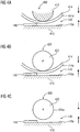
- Fig. 4a shows a cross section through an arrangement for forming a gap.
- the arrangement according to the Fig. 4a is designated in its entirety by 400 and includes a first guide member 412 which serves as a guide for a belt or a band 414.
- the arrangement 400 comprises a second guide element 416.
- the gap 140 thus exists between the belt or band 414 and the second guide element 416.
- a guide so that the relative position of the first guide member 412 and the second guide member 416 to each other can be changed in order to adjust the gap width of the gap can.
- a device not shown in detail e.g, a guide
- a guide allows to bring the material to be conveyed in the gap.
- a lower surface 414a of the belt or belt 414 forms the first material surface
- the upper surface 416a of the second guide element 416 forms the second material surface.
- the guide element 412 does not necessarily have to be a rotatably mounted component. Rather, a substantially torsionally rigidly mounted component, for example a rounded or curved guide plate, can be used.
- Fig. 4b shows a cross section through a further arrangement for providing a gap.
- the arrangement according to the Fig. 4b is designated 420 in its entirety.
- the arrangement 420 differs from the arrangement 400 according to FIG Fig. 4a merely in that the guide element 412 is replaced by a guide roller 422.
- the guide roller 422 is preferably rotatably mounted. Further, the guide roller 422 is mounted in one embodiment so that it is displaceable relative to the second guide member 416, so that the gap width of the gap 140 is adjustable.
- the roller 422 may serve as a drive for the belt 414 or may merely form a passive (non-driven) guide roller.
- Fig. 4c shows a cross-sectional view of an arrangement for providing a gap.
- the arrangement according to the Fig. 4c is designated in its entirety with 430.
- the arrangement 430 substantially corresponds to the arrangement 420 according to FIG Fig. 4b , However, in the embodiment according to the Fig. 4c dispensed on the belt or the band 414.
- the surface 434a of the roller 422 serves as the first material surface
- a surface 416a of the second guide member 416 serves as the second material surface.
- the roller 422 is for example rotatably mounted and can be driven in one embodiment.
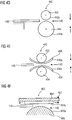
- Fig. 4d shows a cross-sectional view of another arrangement for the realization of a gap, according to another embodiment of the present invention.
- the arrangement according to Fig. 4d is designated 440 in its entirety.
- the assembly 440 includes a first roller 442 and a second roller 444.
- a surface 442a of the first roller 442 serves, for example, as the first material surface, while a surface 444a of the second roller 444 serves as the second material surface.
- the first roller 442 is a driven roller while the second roller 444 is a non-driven (passive) roller.
- the two rollers 442, 444 are driven. Furthermore, it is not absolutely necessary that both rollers 442, 444 are rotatably mounted. Rather, it is sufficient if only one of the two rollers is rotatably mounted.
- the rollers 442, 444 are supported so that a gap width between the surfaces 442a, 444a through which the product can be conveyed is adjustable.
- a gap width between the surfaces 442a, 444a through which the product can be conveyed is adjustable.
- only one of the rollers can be movable, or both rollers can be movable.
- Fig. 4e shows a cross-sectional view of another arrangement for the realization of a gap.
- the arrangement according to the Fig. 4e is designated in its entirety by 450.
- the assembly 450 includes, for example, two rollers 452, 454, both of which may be rotatably mounted. Via the first roller 452, a first belt or belt 456 is guided, and via the second roller 454, a second belt or belt 458 is guided.
- a surface 456a of the first belt 456 forms the first material surface
- a surface 458a of the second belt 458 forms the second material surface. It should be noted that the first belt 456 and / or the second belt 458 may be driven.
- the drive can be done for example via the rollers 452 and / or 454, or by other drive means, which are not shown here.
- the rollers 452, 454 are arranged so that the gap width of the gap between the first surface 456a and the second surface 458a can be changed.
- Fig. 4f shows a cross-sectional view of another arrangement for the realization of a gap, according to another embodiment.
- the arrangement according to the Fig. 4f is designated in its entirety with 460.
- the assembly 460 includes a linear actuator 462 having a driven member 464.
- a surface 464a of the driven member 464 may form the first material surface.
- the arrangement 460 comprises a second guide element or a solid component 466, whose surface 466a forms the second material surface.
- the gap 140 exists between the surface 464a of the driven member 464 and the surface 466a of the second guide member.
- the linear drive 462 may, for example, be designed to drive the driven component 464 with a specific, specifiable or predeterminable force.
- the first surface of the gap 140 be directly formed by a surface of the driven member 464.
- a transmission means for example, a belt, a belt, a gear or other mechanical transmission means
- a transmission means may be provided to transmit the force provided by the linear drive 462 force on a located in the region of the gap 140 first material surface.
- both surfaces that is, for example, both the first material surface, which forms a first boundary of the gap, and the second material surface, which forms a second boundary of the gap
- both surfaces that is, for example, both the first material surface, which forms a first boundary of the gap
- the second material surface which forms a second boundary of the gap
- the first material surface and the second material surface may be driven in the same directions with respect to the product.
- the same speeds or different speeds for the relative movement of the first material surface with respect to the material or for the relative movement of the second material surface with respect to the material can be selected.
- the first surface and the second surface may be driven in different or opposite directions with respect to the material. As a result, for example, a total force can be reduced to the good.
- Fig. 5 shows a cross-sectional view of an arrangement for realizing a gap, according to another embodiment of the present invention.
- the arrangement according to the Fig. 5 is designated in its entirety by 500.
- the assembly 500 includes a belt or strap 510 and a plate 520.
- the plate 520 acts as a guide plate to guide the goods to a gap between the plate 520 and the strap 510.
- the gap is designated 140.
- the assembly 500 further includes a drive member 530 configured to drive the belt 510 using, for example, a predetermined drive force or using a predetermined drive torque.
- the drive member 530 may include, for example, a driven roller.
- the assembly 500 includes means configured to move the sheet 520 toward the belt 510 with a force F (which may differ from the driving force to drive the belt 510) toward the belt to press.
- a force F which may differ from the driving force to drive the belt 510
- the width of the gap 140 is reduced.
- Fig. 6 shows for this purpose a flowchart of a method for adjusting the operating gap width.
- the method according to Fig. 6 is designated in its entirety by 600.
- the method 600 includes a first step 610 in which the first material surface is set in motion.
- a predetermined driving force which may also be defined by a predetermined drive torque, is used.
- the method 600 further includes a second step 620 of reducing the gap width until the first material surface is decelerated to a predetermined speed v 0 .
- the gap width is reduced continuously or stepwise until the predetermined speed is reached.
- the driving force or the drive torque is preferably kept constant.
- the default speed can be greater than or equal to zero. If the predetermined speed is chosen equal to zero, this corresponds to a complete blocking of the movement of the first material surface. If it is detected that the first material surface has reached the predetermined speed or has been braked to the predetermined speed, a gap width is identified which is assigned to this state. In a third step 630, an operating gap width is then set as a function of the identified gap width.
- Fig. 7 shows a flowchart of another method for setting an operating gap width.
- the method according to the Fig. 7 is designated in its entirety by 700.
- the method 700 comprises, in a first step, moving the first material surface in motion.
- a driving force is used, and it is further set the driving force so that the first material surface moves with at least a predetermined minimum speed with respect to the good.
- a speed control can be carried out, for example, whereby the speed of the first material surface is regulated. It can be assumed, for example, that the estate is recorded.
- the gap width is reduced until the driving force reaches a predetermined value. In other words, the narrower the gap width, the greater the friction between the first material surface and the product. Therefore, the driving force required to maintain the predetermined minimum speed becomes larger and larger. If the gap width reaches a certain value, the required driving force thus reaches the predetermined value. The corresponding gap width is thus identified as the identified gap width.
- the operating gap width is then set as a function of the identified gap width.
- the operating gap width may be larger than the identified gap width by a predetermined value.
- the operating gap width can be selected equal to the identified gap width.
- a fine adjustment of the gap width can take place.
- the method of the invention may be implemented in hardware or in software.
- the implementation may be on a digital storage medium, eg a floppy disk or CD, with electronically readable control signals that may interact with a programmable computer system such that the corresponding method is executed.
- the invention thus also consists in a computer program product with program code stored on a machine-readable carrier for carrying out the method according to exemplary embodiments of the invention, when the computer program product runs on a computer.
- the invention can thus be realized as a computer program with a program code for carrying out the method when the computer program runs on a computer.
- FIG. 8 shows a schematic representation of a method for adjusting the lock gap.
- the method according to the Fig. 8 is different from the procedure as it is based on the FIGS. 2A and 2B essentially, by moving the counter roll 130 away from the material 148 during the process, so that in carrying out the process a gap width between the roller 110a and the counter roller 130 is increased.
- the estate 148 may be defined by retaining elements included in the Fig. 8 shown schematically, and which are designated 810a, 810b, are held.
- a gap width between the roller 110a and the counter roller 130 may be reduced so far in an initial state that there is strong stiction between the counter roller 130 and a surface of the article 148.
- the counter-roller 130 can be acted upon, for example, with a drive effect, which acts on a rotation of the counter-roller 130.
- the drive effect can, for example, act on a movement of the surface of the counter roll 130 tangentially to the gap, so that the drive effect leaves the gap width unchanged.
- a torque acting on the counter-roller 130 can, for example, act on a movement of the surface of the counter roll 130 tangentially to the gap, so that the drive effect leaves the gap width unchanged.
- the stiction between the surface of the article 148 and the counter-roller 130 may cause the counter-roller 130 to move in spite of the effect of the driving (or driving) torque. not turning.
- the movement of the surface of the counter roll 130 with respect to the material 148 is thus inhibited by a static friction.
- the width of the gap between the roller 110a and the counter roller 130 is increased in the method.
- the counter-roller 130 is further subjected to the drive effect, for example in the form of an acting torque.
- the gap width increased sufficiently strong the static friction between the surface of the material 148 and the counter-roller 130 decreases until the counter-roller 130, for example, due to the driving effect acting on them, sets in the presence of a certain gap width in motion. From this point, it can therefore be assumed that in the gap width at which the counter-roller 130 sets in motion, the frictional force transmitted to the counter-roller by the surface of the goods 148 is smaller than the drive effect acting on the counter-roller 130.
- an inhibition of the drive effect for example a frictional force exerted by the surface of the material 148 on the counter roller 130
- the gap width between the roller 110a and the counter roller 130 reaches or falls below a predetermined value
- the gap width can be adjusted. For example, as the desired lock setting that gap width can be used at which the counter-roller 130 is just starting to move. However, it is also possible to set the desired lock setting on the basis of the value of the gap width at which the counter roll is just starting to move, eg a specific change in the gap width can be made. Further, based on the determination of which gap width the counter roll 130 is moving, a multi-step gap width adjustment method may be initiated as shown, for example, in US Pat Fig. 3 already described.
- the method according to the Fig. 9 is designated in its entirety by 900.
- the method 900 includes, in a step 910, impacting the first material surface with a driving action that is responsive to movement of the first material surface with respect to the material, such that the first material surface moves Driving effect leaves a gap width between the first material surface and the second material surface unchanged.
- a driving action that is responsive to movement of the first material surface with respect to the material, such that the first material surface moves
- Driving effect leaves a gap width between the first material surface and the second material surface unchanged.
- counter roller 130 can be subjected to a torque.
- the good to be promoted is located in the gap. Further, in the step 910, for example, the movement of the first material surface with respect to the material is inhibited by a frictional force between the first material surface and the material.
- a step 920 for example, the gap width is increased, wherein the first material surface continues to be acted upon by the drive effect.
- the gap width is set based on when (eg at which gap width) an inhibition of the driving force by the frictional force increases or falls below a predetermined value (or, more generally, when the inhibition of the driving action has a certain condition) Fulfills).
- the gap width may be increased, with the first material surface still being imparted with the drive effect, until an inhibition of the drive effect by the frictional force in increasing the gap width satisfies a predetermined condition.
- the property 148 in addition to being in contact with the roller 110a and the counter-roller 130, to be acted upon by a driving action.
- This drive effect can be exerted on the material 148, for example by further rollers 1010a, 1010b.
- the gap between the counter roll 130 and the roll 110a can be set as follows:
- the material 148 which is located in the gap between the roller 110a and the counter-roller 130, can for example be acted upon by the further rollers 1010a, 1010b with a driving action, which acts on a relative movement between the surface of the counter-roller 130 and the material.
- the counter-roller 130 can be acted on (for example by a correspondingly driven motor, by a brake or by another means) with a holding action, which counteracts a rotation of the counter-roller 130.
- the gap width between the roller 110a and the counter-roller 130 can be changed, wherein the material to be conveyed 148 is in the gap to determine at which gap width an inhibition that counteracts a relative movement between the surface of the counter-roller 130 and the estate 148 satisfies a predetermined condition. Further, generally speaking, the gap width can be adjusted based on which gap width the inhibition meets the predetermined condition.
- the product 148 may be driven with a predetermined drive effect.
- one of the rollers 1010a, 1010b (or both rollers) may be driven at a predetermined torque. If the material 148 is driven with a predetermined torque, and further, the distance between the roller 110a and the counter-roller 130 is increasingly reduced, the material 148 comes in one embodiment from a certain gap width to stop. If it is assumed that the rollers 1010a, 1010b rest sufficiently firmly against the material 148, the rollers 110a, 110b also come to stop correspondingly, which are evaluated, for example, by a simple speed sensor which is connected to one of the rollers 1010a, 1010b can. Based on the determination of the gap width at which the material or the rotation of one of the rollers 1010a, 1010b is decelerated in a predetermined manner (for example up to a predetermined speed or until standstill), then an operating gap width can be set.
- the stock 148 moves between the roll 110a and the counter roll 130 while reducing the nip width. This can avoid that a certain surface area of the material 148 is flattened particularly strong. Thus, in some embodiments, a very precise adjustment of the gap width (sometimes even in a one-step process) is possible.
- Fig. 11 shows a method 1100 for adjusting a gap between a first material surface and a second material surface through which a product is to be conveyed.
- the method 1100 includes, in a step 1110, subjecting a material to be conveyed located in the gap between the first material surface and the second material surface to a driving action that is responsive to relative movement between the first material surface and the product.
- the first material surface is acted upon in the step 1110 with a holding action, which counteracts a movement of the first material surface such that a gap width between the first material surface and the second material surface remains unchanged.
- the method 1100 includes varying the nip width in a step 1120 wherein the product to be conveyed is in the nip to determine at which nip width an escapement that opposes relative movement between the first material surface and the product meets a predetermined condition.
- the first material surface may still be subjected to a holding action.
- the method 1100 includes, in a step 1130, adjusting the slit width based on which slit width the inhibit reaches the predetermined condition.
- the first material surface may be driven when performing the method 1100.
- the first surface of the material may be a fixed surface that is rotationally fixed, for example.
- the Fig. 12 shows a flowchart of a method for adjusting a gap between a first material surface and a second material surface through which a product is to be conveyed.
- the method 1200 comprises, in a step 1210, exerting a drive action which acts on a relative movement between the first material surface and a material to be conveyed in the gap, such that the drive action leaves a gap width between the first material surface and the second material surface unchanged.
- the method 1200 includes, in a step 1220, varying the nip width to determine at which nip width an escapement that opposes the relative movement between the first material surface and the product to be conveyed meets a predetermined condition.
- the method 1200 further includes, in a step 1230, adjusting the gap width based on determining which gap width the inhibition meets the predetermined condition.
- a control circuit for adjusting a gap between a first material surface and a second material surface through which a product is conveyed
- the control circuit may be configured to implement methods as described herein.
Landscapes
- Engineering & Computer Science (AREA)
- Mechanical Engineering (AREA)
- Delivering By Means Of Belts And Rollers (AREA)
- Sheets, Magazines, And Separation Thereof (AREA)
- Control Of Electric Motors In General (AREA)
Claims (16)
- Procédé permettant de régler un interstice entre une première surface de matériau et une deuxième surface de matériau à travers lequel doit être acheminé un produit, aux étapes suivantes consistant à:(a) soumettre un produit à acheminer qui se trouve dans l'interstice entre la première surface de matériau et la deuxième surface de matériau à une action d'entraînement qui agit sur un mouvement relatif entre la première surface de matériau et le produit; et(b) modifier la largeur d'interstice, où le produit à acheminer se trouve dans l'interstice jusqu'à ce qu'un blocage qui s'oppose à un mouvement relatif entre la première surface de matériau et le produit remplisse une condition prédéterminée,dans lequel l'étape (a) comporte un déplacement de la première surface de matériau en un mouvement par une action d'entraînement de sorte que la première surface de matériau se déplace par rapport au produit de sorte que reste inchangée une largeur d'interstice entre la première surface de matériau et la deuxième surface de matériau;
dans lequel l'étape (b) comporte une réduction de la largeur d'interstice, où le produit à acheminer se trouve dans l'interstice jusqu'à ce qu'un blocage de l'action d'entraînement remplisse une condition prédéterminée; et
dans lequel l'étape (b) comporte les étapes suivantes consistant à:(b.1) réduire pas à pas (S106) la largeur d'interstice à l'aide d'une première largeur de pas jusqu'à ce que le blocage remplisse la condition prédéterminée;(b.2) augmenter pas à pas (S108) la largeur d'interstice à l'aide d'une deuxième largeur de pas qui est inférieure à la première largeur de pas jusqu'à ce que le blocage remplisse une autre condition prédéterminée;(b.3) réduire pas à pas (S112) la largeur d'interstice à l'aide d'une troisième largeur de pas qui est inférieure à la deuxième largeur de pas jusqu'à ce que le blocage remplisse la condition prédéterminée;(b.4) déplacer (S116) le produit (148) d'une distance prédéterminée; et(b.5) augmenter pas à pas (S118) la largeur d'interstice à l'aide d'une quatrième largeur de pas qui est inférieure à la troisième largeur de pas jusqu'à ce que le blocage remplisse l'autre condition prédéterminée. - Procédé selon la revendication 1, dans lequel la première surface de matériau est fixée de manière immobile dans une direction de transport ou de manière non déplaçable dans la direction de transport, ou est mobile ou entraînée dans la direction de transport.
- Procédé selon la revendication 1 ou 2, dans lequel une constatation de la largeur d'interstice à laquelle le blocage remplit la condition prédéterminée comprend ce qui suit:une constatation de la largeur d'interstice à laquelle une action de freinage exercée par la première surface sur le produit ou sur un élément d'entraînement qui transmet l'action d'entraînement au produit remplit une condition prédéterminée, ouune constatation de la largeur d'interstice à laquelle est arrêté un mouvement du produit ou de l'élément d'entraînement, ou une constatation de la largeur d'interstice à laquelle le produit ou l'élément d'entraînement commence un mouvement, ouune constatation de la largeur d'interstice à laquelle une action d'entraînement qui est transmise par le produit à la première surface remplit une condition prédéterminée, ouune constatation de la largeur d'interstice à laquelle la première surface se met en mouvement par transmission d'une force du produit à la première surface, ouune constatation de la largeur d'interstice à laquelle la première surface vient en position de repos.
- Procédé selon l'une des revendications 1 à 3, dans lequel le déplacement de la surface de matériau en un mouvement comporte le fait d'entraîner un élément rotatif (110a, 130) à un couple de rotation prédéterminé.
- Procédé selon l'une des revendications 1 à 3, dans lequel la réduction de la largeur d'interstice jusqu'à ce que le blocage de l'action d'entraînement remplisse une condition prédéterminée comporte un déplacement (S104 à S120) d'un élément rotatif (110a, 130) contre le produit disposé dans l'interstice (140) jusqu'à ce que l'élément rotatif (110a, 130) s'arrête.
- Procédé selon l'une des revendications 1 à 5, dans lequel le produit (148) est déplacé d'une distance de sorte que la première surface de matériau puisse entrer en contact avec une zone du produit (148) qui n'était pas encore en contact auparavant avec la première surface de matériau.
- Procédé selon l'une des revendications 1 à 6, dans lequel l'étape (a) comporte l'application d'une énergie prédéterminée à un moteur d'un élément d'entraînement en vue d'obtenir l'action d'entraînement qui est choisie en fonction d'une force de retenue souhaitée dans l'interstice pour régler un couple de rotation prédéterminé, où un courant appliqué au moteur est réglé en fonction de la force de retenue souhaitée.
- Procédé selon l'une des revendications 1 à 7, aux étapes suivantes, avant l'étape (a), consistant à:appliquer un produit (148) à l'interstice (140);ouvrir l'interstice (140);introduire le produit (148) dans l'interstice (140); etarrêter le produit (148) dans l'interstice (140).
- Procédé selon l'une des revendications 1 à 8, dans lequel les étapes (a) et (b) sont répétées lorsqu'il se produit un événement prédéterminé, où l'événement prédéterminé est choisi dans un groupe qui comporte des moments ou intervalles de temps prédéterminés après un réglage de l'interstice (140) effectué, un nombre prédéterminé de produits acheminés (148) et la production d'erreurs prédéterminées.
- Procédé selon l'une des revendications 1 à 9, dans lequel l'interstice entre deux éléments de transport (110a, 130) d'un mécanisme de transport pour acheminer des produits (148) est formé dans une direction de transport.
- Procédé selon la revendication 10, dans lequel un des éléments de transport (110a, 130) est l'élément rotatif, dans lequel l'étape (a) comporte l'entraînement de l'un des éléments de transport (110a, 130) avec le couple de rotation prédéterminé, et dans lequel l'étape (b) comporte la fermeture (S104 à S120) de l'interstice (140) jusqu'à ce que l'élément de transport entraîné (130) s'arrête, dans lequel l'un des éléments de transport (110a, 130) est entraîné dans la direction opposée à la direction de transport, et dans lequel les éléments de transport du mécanisme de transport pour acheminer des produits (148) dans une direction de transport comportent une paire de rouleaux, une paire de cylindres, une paire de courroies, une combinaison de cylindre et courroie ou une combinaison de rouleau et courroie.
- Procédé selon l'une des revendications 1 à 11, dans lequel l'étape (a) comporte un entraînement de la première surface de matériau de sorte que la première surface de matériau se déplace par rapport au produit à une vitesse prédéterminée; et
dans l'étape (b), une réduction de la largeur d'interstice jusqu'à ce qu'une force d'entraînement nécessaire pour entraîner la première surface de matériau atteigne une valeur prédéterminée. - Procédé selon l'une des revendications 1 à 12, dans lequel la réduction de la largeur d'interstice est arrêtée lorsque le blocage de l'action d'entraînement remplit la condition prédéterminée, ou dans lequel la largeur d'interstice est davantage réduite lorsque le blocage de l'action d'entraînement ne remplit pas la condition prédéterminée.
- Programme d'ordinateur avec un code de programme pour la mise en oeuvre du procédé selon l'une des revendications 1 à 13 lorsque le programme est exécuté sur un ordinateur.
- Circuit de commande permettant de régler un interstice entre une première surface de matériau et une deuxième surface de matériau à travers lequel doit être acheminé un produit, où le circuit de commande est configuré pour mettre en oeuvre un procédé selon l'une des revendications 1 à 14.
- Dispositif de manipulation de papier avec un circuit de commande (120) selon la revendication 15.
Applications Claiming Priority (2)
| Application Number | Priority Date | Filing Date | Title |
|---|---|---|---|
| DE102007016589A DE102007016589A1 (de) | 2007-04-05 | 2007-04-05 | Verfahren und Steuerungsschaltung zum Einstellen eines Spalts |
| PCT/EP2008/002745 WO2008122433A1 (fr) | 2007-04-05 | 2008-04-07 | Procédé et circuit de commande permettant de régler un interstice |
Publications (2)
| Publication Number | Publication Date |
|---|---|
| EP2132117A1 EP2132117A1 (fr) | 2009-12-16 |
| EP2132117B1 true EP2132117B1 (fr) | 2018-10-31 |
Family
ID=39577704
Family Applications (1)
| Application Number | Title | Priority Date | Filing Date |
|---|---|---|---|
| EP08735065.8A Active EP2132117B1 (fr) | 2007-04-05 | 2008-04-07 | Procédé et circuit de commande permettant de régler un interstice |
Country Status (5)
| Country | Link |
|---|---|
| US (1) | US8825204B2 (fr) |
| EP (1) | EP2132117B1 (fr) |
| JP (1) | JP2010523433A (fr) |
| DE (1) | DE102007016589A1 (fr) |
| WO (1) | WO2008122433A1 (fr) |
Families Citing this family (6)
| Publication number | Priority date | Publication date | Assignee | Title |
|---|---|---|---|---|
| US8083232B2 (en) * | 2009-08-25 | 2011-12-27 | Xerox Corporation | Substrate media transport system with spaced nip |
| US8727099B2 (en) | 2010-05-24 | 2014-05-20 | Usnr/Kockums Cancar Company | Tapered roll feed |
| CA2869064C (fr) | 2012-11-21 | 2016-01-19 | Usnr/Kockums Cancar Company | Systemes, procedes et appareils pour modifier la direction ou la vitesse d'une piece |
| JP6082290B2 (ja) * | 2013-03-19 | 2017-02-15 | 株式会社Pfu | 媒体供給装置 |
| US9171430B2 (en) * | 2013-08-06 | 2015-10-27 | Ncr Corporation | Media item transporter |
| CN112757079B (zh) * | 2020-12-31 | 2022-05-17 | 泉州市海恩德机电科技发展有限公司 | 一种智能化石材打磨设备 |
Citations (3)
| Publication number | Priority date | Publication date | Assignee | Title |
|---|---|---|---|---|
| EP0776845A1 (fr) * | 1995-12-01 | 1997-06-04 | Mathias Bäuerle GmbH | Fente de séparation adjustable pour des feuilles en papier et similaire |
| WO1998004484A1 (fr) * | 1996-07-25 | 1998-02-05 | Siemens Nixdorf Informationssysteme Ag | Dispositif de separation a interstice de separation reglable |
| DE29823055U1 (de) * | 1998-12-18 | 1999-05-06 | Francotyp-Postalia AG & Co., 16547 Birkenwerder | Vorrichtung zum Vereinzeln flacher Gegenstände unterschiedlicher Dicke und Größe von einem Stapel |
Family Cites Families (8)
| Publication number | Priority date | Publication date | Assignee | Title |
|---|---|---|---|---|
| DE2914097A1 (de) * | 1979-04-07 | 1980-10-16 | Pixa Joachim W Fa | Vorrichtung zum vereinzeln von einen stapel bildenden blaettern bzw. blattgruppen |
| JPS60213642A (ja) * | 1984-04-06 | 1985-10-25 | Laurel Bank Mach Co Ltd | 紙幣繰り出し装置 |
| US5203846A (en) * | 1991-11-12 | 1993-04-20 | A. B. Dick Company | Media feed roll apparatus and method for its use |
| US5435540A (en) * | 1992-12-01 | 1995-07-25 | Xerox Corporation | Apparatus and method for sheet feeding and separating using retard roll relief/enhancement |
| DE29516265U1 (de) * | 1995-10-13 | 1995-12-07 | Mathias Bäuerle GmbH, 78112 St Georgen | Stauchfalzmaschine mit einer Sammelfalztasche |
| GB9718798D0 (en) * | 1997-09-05 | 1997-11-12 | Ncr Int Inc | Document feeding apparatus |
| US6234470B1 (en) * | 1998-03-18 | 2001-05-22 | Canon Denshi Kabushiki Kaisha | Sheet material feeding apparatus |
| US6354583B1 (en) | 1999-01-25 | 2002-03-12 | Bell & Howell Mail And Messaging Technologies Company | Sheet feeder apparatus and method with throughput control |
-
2007
- 2007-04-05 DE DE102007016589A patent/DE102007016589A1/de not_active Withdrawn
-
2008
- 2008-04-07 US US12/532,631 patent/US8825204B2/en active Active
- 2008-04-07 EP EP08735065.8A patent/EP2132117B1/fr active Active
- 2008-04-07 JP JP2010501446A patent/JP2010523433A/ja active Pending
- 2008-04-07 WO PCT/EP2008/002745 patent/WO2008122433A1/fr not_active Ceased
Patent Citations (3)
| Publication number | Priority date | Publication date | Assignee | Title |
|---|---|---|---|---|
| EP0776845A1 (fr) * | 1995-12-01 | 1997-06-04 | Mathias Bäuerle GmbH | Fente de séparation adjustable pour des feuilles en papier et similaire |
| WO1998004484A1 (fr) * | 1996-07-25 | 1998-02-05 | Siemens Nixdorf Informationssysteme Ag | Dispositif de separation a interstice de separation reglable |
| DE29823055U1 (de) * | 1998-12-18 | 1999-05-06 | Francotyp-Postalia AG & Co., 16547 Birkenwerder | Vorrichtung zum Vereinzeln flacher Gegenstände unterschiedlicher Dicke und Größe von einem Stapel |
Also Published As
| Publication number | Publication date |
|---|---|
| EP2132117A1 (fr) | 2009-12-16 |
| WO2008122433A1 (fr) | 2008-10-16 |
| JP2010523433A (ja) | 2010-07-15 |
| US8825204B2 (en) | 2014-09-02 |
| US20100191368A1 (en) | 2010-07-29 |
| DE102007016589A1 (de) | 2008-10-09 |
Similar Documents
| Publication | Publication Date | Title |
|---|---|---|
| EP1084072B1 (fr) | Dispositif et procede pour separer des supports d'impression sous forme de feuilles empiles | |
| EP2132117B1 (fr) | Procédé et circuit de commande permettant de régler un interstice | |
| DE2935653C2 (de) | Vorrichtung zum Vereinzeln von gestapelten Papierblättern | |
| EP3694799B1 (fr) | Dispositif d'orientation de feuille, machine pour le traitement d'une feuille ainsi que procédé pour l'orientation d'une feuille | |
| DE69316457T2 (de) | Blattzuführvorrichtung | |
| EP1513753B1 (fr) | Dispositif de separation de produits en forme de feuillets | |
| EP1663828B1 (fr) | Procede et dispositif pour separer des produits sous forme de feuille | |
| EP3533609B1 (fr) | Dispositif et procédé de traitement ultérieur séquentiel de feuilles imprimées | |
| DE19515506B4 (de) | Einrichtung zum Verarbeiten von Druckereiprodukten | |
| EP1603818A1 (fr) | Procede et dispositif pour traiter une bande en papier ou en matiere pour film | |
| DE3503168C2 (fr) | ||
| DE102009021320A1 (de) | Vorrichtung und Verfahren zur Vereinzelung von Wertscheinen eines Wertscheinstapels | |
| EP2467323B1 (fr) | Applicateur de frottement et installation d'emballage pour un applicateur de frottement | |
| EP1832536B1 (fr) | Dispositif pour le traitement et/ou le transport d'articles postaux plats | |
| EP1360130A2 (fr) | Dispositif et procede pour la separation d'articles en feuilles | |
| EP2017210B1 (fr) | Procédé destiné au fonctionnement d'un appareil de pliage en longueur | |
| WO2007082884A1 (fr) | Dispositif pour deposer des feuilles en piles | |
| EP3186091B1 (fr) | Dispositif d'insertion de documents | |
| DE69208593T2 (de) | Vorrichtung zum Vereinzeln und Zuführen von Papierblättern und Steuerungsverfahren dafür, und dieses Verfahren verwendender Kassenautomat | |
| EP0017227A1 (fr) | Dispositif pour le démariage des feuilles composant une pile | |
| CH712159A2 (de) | Verfahren und Vorrichtung für den Transport von dickenvariablen Druckprodukten. | |
| DE69214716T2 (de) | Blattzuführeinrichtung mit einer oder mehreren Schichten | |
| EP0934221B1 (fr) | Procede et dispositifs pour introduire un materiau sous forme de feuille dans une imprimante ou une photocopieuse | |
| EP4065496B1 (fr) | Appareil pour faire tourner des objets allongés | |
| EP1344736B1 (fr) | Dispositif pour transporter des billets de banque |
Legal Events
| Date | Code | Title | Description |
|---|---|---|---|
| PUAI | Public reference made under article 153(3) epc to a published international application that has entered the european phase |
Free format text: ORIGINAL CODE: 0009012 |
|
| 17P | Request for examination filed |
Effective date: 20090922 |
|
| AK | Designated contracting states |
Kind code of ref document: A1 Designated state(s): AT BE BG CH CY CZ DE DK EE ES FI FR GB GR HR HU IE IS IT LI LT LU LV MC MT NL NO PL PT RO SE SI SK TR |
|
| DAX | Request for extension of the european patent (deleted) | ||
| RAP1 | Party data changed (applicant data changed or rights of an application transferred) |
Owner name: BOEWE SYSTEC GMBH |
|
| 17Q | First examination report despatched |
Effective date: 20130701 |
|
| STAA | Information on the status of an ep patent application or granted ep patent |
Free format text: STATUS: EXAMINATION IS IN PROGRESS |
|
| GRAP | Despatch of communication of intention to grant a patent |
Free format text: ORIGINAL CODE: EPIDOSNIGR1 |
|
| STAA | Information on the status of an ep patent application or granted ep patent |
Free format text: STATUS: GRANT OF PATENT IS INTENDED |
|
| INTG | Intention to grant announced |
Effective date: 20180516 |
|
| GRAS | Grant fee paid |
Free format text: ORIGINAL CODE: EPIDOSNIGR3 |
|
| GRAA | (expected) grant |
Free format text: ORIGINAL CODE: 0009210 |
|
| STAA | Information on the status of an ep patent application or granted ep patent |
Free format text: STATUS: THE PATENT HAS BEEN GRANTED |
|
| AK | Designated contracting states |
Kind code of ref document: B1 Designated state(s): AT BE BG CH CY CZ DE DK EE ES FI FR GB GR HR HU IE IS IT LI LT LU LV MC MT NL NO PL PT RO SE SI SK TR |
|
| REG | Reference to a national code |
Ref country code: CH Ref legal event code: EP Ref country code: GB Ref legal event code: FG4D Free format text: NOT ENGLISH |
|
| REG | Reference to a national code |
Ref country code: AT Ref legal event code: REF Ref document number: 1059113 Country of ref document: AT Kind code of ref document: T Effective date: 20181115 |
|
| REG | Reference to a national code |
Ref country code: DE Ref legal event code: R096 Ref document number: 502008016425 Country of ref document: DE |
|
| REG | Reference to a national code |
Ref country code: IE Ref legal event code: FG4D Free format text: LANGUAGE OF EP DOCUMENT: GERMAN |
|
| REG | Reference to a national code |
Ref country code: CH Ref legal event code: NV Representative=s name: BOVARD AG PATENT- UND MARKENANWAELTE, CH |
|
| REG | Reference to a national code |
Ref country code: NL Ref legal event code: MP Effective date: 20181031 |
|
| REG | Reference to a national code |
Ref country code: LT Ref legal event code: MG4D |
|
| PG25 | Lapsed in a contracting state [announced via postgrant information from national office to epo] |
Ref country code: ES Free format text: LAPSE BECAUSE OF FAILURE TO SUBMIT A TRANSLATION OF THE DESCRIPTION OR TO PAY THE FEE WITHIN THE PRESCRIBED TIME-LIMIT Effective date: 20181031 Ref country code: IS Free format text: LAPSE BECAUSE OF FAILURE TO SUBMIT A TRANSLATION OF THE DESCRIPTION OR TO PAY THE FEE WITHIN THE PRESCRIBED TIME-LIMIT Effective date: 20190228 Ref country code: BG Free format text: LAPSE BECAUSE OF FAILURE TO SUBMIT A TRANSLATION OF THE DESCRIPTION OR TO PAY THE FEE WITHIN THE PRESCRIBED TIME-LIMIT Effective date: 20190131 Ref country code: LT Free format text: LAPSE BECAUSE OF FAILURE TO SUBMIT A TRANSLATION OF THE DESCRIPTION OR TO PAY THE FEE WITHIN THE PRESCRIBED TIME-LIMIT Effective date: 20181031 Ref country code: NO Free format text: LAPSE BECAUSE OF FAILURE TO SUBMIT A TRANSLATION OF THE DESCRIPTION OR TO PAY THE FEE WITHIN THE PRESCRIBED TIME-LIMIT Effective date: 20190131 Ref country code: FI Free format text: LAPSE BECAUSE OF FAILURE TO SUBMIT A TRANSLATION OF THE DESCRIPTION OR TO PAY THE FEE WITHIN THE PRESCRIBED TIME-LIMIT Effective date: 20181031 Ref country code: LV Free format text: LAPSE BECAUSE OF FAILURE TO SUBMIT A TRANSLATION OF THE DESCRIPTION OR TO PAY THE FEE WITHIN THE PRESCRIBED TIME-LIMIT Effective date: 20181031 Ref country code: HR Free format text: LAPSE BECAUSE OF FAILURE TO SUBMIT A TRANSLATION OF THE DESCRIPTION OR TO PAY THE FEE WITHIN THE PRESCRIBED TIME-LIMIT Effective date: 20181031 Ref country code: PL Free format text: LAPSE BECAUSE OF FAILURE TO SUBMIT A TRANSLATION OF THE DESCRIPTION OR TO PAY THE FEE WITHIN THE PRESCRIBED TIME-LIMIT Effective date: 20181031 |
|
| PG25 | Lapsed in a contracting state [announced via postgrant information from national office to epo] |
Ref country code: NL Free format text: LAPSE BECAUSE OF FAILURE TO SUBMIT A TRANSLATION OF THE DESCRIPTION OR TO PAY THE FEE WITHIN THE PRESCRIBED TIME-LIMIT Effective date: 20181031 Ref country code: SE Free format text: LAPSE BECAUSE OF FAILURE TO SUBMIT A TRANSLATION OF THE DESCRIPTION OR TO PAY THE FEE WITHIN THE PRESCRIBED TIME-LIMIT Effective date: 20181031 Ref country code: GR Free format text: LAPSE BECAUSE OF FAILURE TO SUBMIT A TRANSLATION OF THE DESCRIPTION OR TO PAY THE FEE WITHIN THE PRESCRIBED TIME-LIMIT Effective date: 20190201 Ref country code: PT Free format text: LAPSE BECAUSE OF FAILURE TO SUBMIT A TRANSLATION OF THE DESCRIPTION OR TO PAY THE FEE WITHIN THE PRESCRIBED TIME-LIMIT Effective date: 20190301 |
|
| PG25 | Lapsed in a contracting state [announced via postgrant information from national office to epo] |
Ref country code: CZ Free format text: LAPSE BECAUSE OF FAILURE TO SUBMIT A TRANSLATION OF THE DESCRIPTION OR TO PAY THE FEE WITHIN THE PRESCRIBED TIME-LIMIT Effective date: 20181031 Ref country code: DK Free format text: LAPSE BECAUSE OF FAILURE TO SUBMIT A TRANSLATION OF THE DESCRIPTION OR TO PAY THE FEE WITHIN THE PRESCRIBED TIME-LIMIT Effective date: 20181031 Ref country code: IT Free format text: LAPSE BECAUSE OF FAILURE TO SUBMIT A TRANSLATION OF THE DESCRIPTION OR TO PAY THE FEE WITHIN THE PRESCRIBED TIME-LIMIT Effective date: 20181031 |
|
| REG | Reference to a national code |
Ref country code: DE Ref legal event code: R097 Ref document number: 502008016425 Country of ref document: DE |
|
| PG25 | Lapsed in a contracting state [announced via postgrant information from national office to epo] |
Ref country code: RO Free format text: LAPSE BECAUSE OF FAILURE TO SUBMIT A TRANSLATION OF THE DESCRIPTION OR TO PAY THE FEE WITHIN THE PRESCRIBED TIME-LIMIT Effective date: 20181031 Ref country code: SK Free format text: LAPSE BECAUSE OF FAILURE TO SUBMIT A TRANSLATION OF THE DESCRIPTION OR TO PAY THE FEE WITHIN THE PRESCRIBED TIME-LIMIT Effective date: 20181031 Ref country code: EE Free format text: LAPSE BECAUSE OF FAILURE TO SUBMIT A TRANSLATION OF THE DESCRIPTION OR TO PAY THE FEE WITHIN THE PRESCRIBED TIME-LIMIT Effective date: 20181031 |
|
| PLBE | No opposition filed within time limit |
Free format text: ORIGINAL CODE: 0009261 |
|
| STAA | Information on the status of an ep patent application or granted ep patent |
Free format text: STATUS: NO OPPOSITION FILED WITHIN TIME LIMIT |
|
| 26N | No opposition filed |
Effective date: 20190801 |
|
| PG25 | Lapsed in a contracting state [announced via postgrant information from national office to epo] |
Ref country code: SI Free format text: LAPSE BECAUSE OF FAILURE TO SUBMIT A TRANSLATION OF THE DESCRIPTION OR TO PAY THE FEE WITHIN THE PRESCRIBED TIME-LIMIT Effective date: 20181031 |
|
| REG | Reference to a national code |
Ref country code: BE Ref legal event code: MM Effective date: 20190430 |
|
| GBPC | Gb: european patent ceased through non-payment of renewal fee |
Effective date: 20190407 |
|
| PG25 | Lapsed in a contracting state [announced via postgrant information from national office to epo] |
Ref country code: MC Free format text: LAPSE BECAUSE OF FAILURE TO SUBMIT A TRANSLATION OF THE DESCRIPTION OR TO PAY THE FEE WITHIN THE PRESCRIBED TIME-LIMIT Effective date: 20181031 Ref country code: LU Free format text: LAPSE BECAUSE OF NON-PAYMENT OF DUE FEES Effective date: 20190407 |
|
| PG25 | Lapsed in a contracting state [announced via postgrant information from national office to epo] |
Ref country code: GB Free format text: LAPSE BECAUSE OF NON-PAYMENT OF DUE FEES Effective date: 20190407 |
|
| PG25 | Lapsed in a contracting state [announced via postgrant information from national office to epo] |
Ref country code: BE Free format text: LAPSE BECAUSE OF NON-PAYMENT OF DUE FEES Effective date: 20190430 Ref country code: FR Free format text: LAPSE BECAUSE OF NON-PAYMENT OF DUE FEES Effective date: 20190430 |
|
| PG25 | Lapsed in a contracting state [announced via postgrant information from national office to epo] |
Ref country code: TR Free format text: LAPSE BECAUSE OF FAILURE TO SUBMIT A TRANSLATION OF THE DESCRIPTION OR TO PAY THE FEE WITHIN THE PRESCRIBED TIME-LIMIT Effective date: 20181031 |
|
| PG25 | Lapsed in a contracting state [announced via postgrant information from national office to epo] |
Ref country code: IE Free format text: LAPSE BECAUSE OF NON-PAYMENT OF DUE FEES Effective date: 20190407 |
|
| REG | Reference to a national code |
Ref country code: AT Ref legal event code: MM01 Ref document number: 1059113 Country of ref document: AT Kind code of ref document: T Effective date: 20190407 |
|
| PG25 | Lapsed in a contracting state [announced via postgrant information from national office to epo] |
Ref country code: AT Free format text: LAPSE BECAUSE OF NON-PAYMENT OF DUE FEES Effective date: 20190407 |
|
| PG25 | Lapsed in a contracting state [announced via postgrant information from national office to epo] |
Ref country code: CY Free format text: LAPSE BECAUSE OF FAILURE TO SUBMIT A TRANSLATION OF THE DESCRIPTION OR TO PAY THE FEE WITHIN THE PRESCRIBED TIME-LIMIT Effective date: 20181031 |
|
| PG25 | Lapsed in a contracting state [announced via postgrant information from national office to epo] |
Ref country code: HU Free format text: LAPSE BECAUSE OF FAILURE TO SUBMIT A TRANSLATION OF THE DESCRIPTION OR TO PAY THE FEE WITHIN THE PRESCRIBED TIME-LIMIT; INVALID AB INITIO Effective date: 20080407 Ref country code: MT Free format text: LAPSE BECAUSE OF FAILURE TO SUBMIT A TRANSLATION OF THE DESCRIPTION OR TO PAY THE FEE WITHIN THE PRESCRIBED TIME-LIMIT Effective date: 20181031 |
|
| P01 | Opt-out of the competence of the unified patent court (upc) registered |
Effective date: 20230527 |
|
| PGFP | Annual fee paid to national office [announced via postgrant information from national office to epo] |
Ref country code: DE Payment date: 20250422 Year of fee payment: 18 |
|
| PGFP | Annual fee paid to national office [announced via postgrant information from national office to epo] |
Ref country code: CH Payment date: 20250501 Year of fee payment: 18 |