EP2133703B1 - Dispositif d'essai pour des composants électriques à haute tension par tension de choc - Google Patents
Dispositif d'essai pour des composants électriques à haute tension par tension de choc Download PDFInfo
- Publication number
- EP2133703B1 EP2133703B1 EP08010755A EP08010755A EP2133703B1 EP 2133703 B1 EP2133703 B1 EP 2133703B1 EP 08010755 A EP08010755 A EP 08010755A EP 08010755 A EP08010755 A EP 08010755A EP 2133703 B1 EP2133703 B1 EP 2133703B1
- Authority
- EP
- European Patent Office
- Prior art keywords
- test arrangement
- arrangement according
- voltage generator
- container
- box
- Prior art date
- Legal status (The legal status is an assumption and is not a legal conclusion. Google has not performed a legal analysis and makes no representation as to the accuracy of the status listed.)
- Not-in-force
Links
Images

Classifications
-
- G—PHYSICS
- G01—MEASURING; TESTING
- G01R—MEASURING ELECTRIC VARIABLES; MEASURING MAGNETIC VARIABLES
- G01R31/00—Arrangements for testing electric properties; Arrangements for locating electric faults; Arrangements for electrical testing characterised by what is being tested not provided for elsewhere
- G01R31/12—Testing dielectric strength or breakdown voltage ; Testing or monitoring effectiveness or level of insulation, e.g. of a cable or of an apparatus, for example using partial discharge measurements; Electrostatic testing
- G01R31/1227—Testing dielectric strength or breakdown voltage ; Testing or monitoring effectiveness or level of insulation, e.g. of a cable or of an apparatus, for example using partial discharge measurements; Electrostatic testing of components, parts or materials
-
- G—PHYSICS
- G01—MEASURING; TESTING
- G01R—MEASURING ELECTRIC VARIABLES; MEASURING MAGNETIC VARIABLES
- G01R31/00—Arrangements for testing electric properties; Arrangements for locating electric faults; Arrangements for electrical testing characterised by what is being tested not provided for elsewhere
- G01R31/28—Testing of electronic circuits, e.g. by signal tracer
- G01R31/2801—Testing of printed circuits, backplanes, motherboards, hybrid circuits or carriers for multichip packages [MCP]
- G01R31/2805—Bare printed circuit boards
-
- G—PHYSICS
- G01—MEASURING; TESTING
- G01R—MEASURING ELECTRIC VARIABLES; MEASURING MAGNETIC VARIABLES
- G01R31/00—Arrangements for testing electric properties; Arrangements for locating electric faults; Arrangements for electrical testing characterised by what is being tested not provided for elsewhere
- G01R31/50—Testing of electric apparatus, lines, cables or components for short-circuits, continuity, leakage current or incorrect line connections
- G01R31/58—Testing of lines, cables or conductors
-
- G—PHYSICS
- G01—MEASURING; TESTING
- G01R—MEASURING ELECTRIC VARIABLES; MEASURING MAGNETIC VARIABLES
- G01R31/00—Arrangements for testing electric properties; Arrangements for locating electric faults; Arrangements for electrical testing characterised by what is being tested not provided for elsewhere
- G01R31/12—Testing dielectric strength or breakdown voltage ; Testing or monitoring effectiveness or level of insulation, e.g. of a cable or of an apparatus, for example using partial discharge measurements; Electrostatic testing
- G01R31/14—Circuits therefor, e.g. for generating test voltages, sensing circuits
-
- G—PHYSICS
- G01—MEASURING; TESTING
- G01R—MEASURING ELECTRIC VARIABLES; MEASURING MAGNETIC VARIABLES
- G01R31/00—Arrangements for testing electric properties; Arrangements for locating electric faults; Arrangements for electrical testing characterised by what is being tested not provided for elsewhere
- G01R31/50—Testing of electric apparatus, lines, cables or components for short-circuits, continuity, leakage current or incorrect line connections
- G01R31/62—Testing of transformers
Definitions
- the invention relates to a mobile test arrangement for surge voltage testing of electrical high-voltage components with a surge voltage generator wherein the surge voltage generator and / or the voltage divider from a first approximately horizontal position in each case approximately vertical position are pivotable and with measuring devices and evaluation devices.
- surge voltage generators are used to test high voltage components, particularly power transformers.
- a voltage pulse can be generated, which is supplied to the test part of the test object, for example a high-voltage winding, by means of a suitable electrical connection of the surge voltage generator and the test object.
- a voltage pulse has a duration in the range of usually up to a few tens of ⁇ s, the maximum voltage is - depending on the device under test - up to a few MV. From the continuous measurement of current and / or voltage values within the electrical circuitry of the test setup when the voltage pulse is applied, information about the condition of the tested component can be derived, for example on the state of aging or even a fault in the electrical insulation.
- a surge voltage generator has a plurality of capacitors, which are first charged to generate a high voltage pulse in electrical parallel connection and then discharged in electrical series connection. By the series connection correspondingly higher voltages can be realized.
- the embodiment of a surge voltage generator according to the general state of the art usually in a tower-like structure, in which the components used capacitor, resistance, spark gap and insulators are assembled in a lattice structure.
- the insulators can also be embodied as tubes made of an insulating material, for example GRP, wherein the insulators are preferably arranged one behind the other along the tower-like structure in the form of a plurality of support columns extending over the entire length of the structure and the electrical components transverse thereto.
- Surge generators are usually only in the vertical, upright condition to operate, because only so all the necessary isolation distances to the adjacent grounded potential are met. The highest voltage occurs at the top of the surge generator.
- High-voltage components such as power transformers have a very high weight, depending on the electrical rated power also several 100 t.
- test arrangement with surge voltage generator and other components required for the test, such as voltage dividers, measuring and evaluation devices, are transported in a plurality of modules to the location at which the transformer to be tested or maintained is located and assembled there to form a test arrangement.
- the voltage divider which is required for measuring the high voltages of, for example, up to 2MV, is in addition to the surge generator a component of considerable size, for example, a height of 10m.
- the disadvantage here is that the on-site assembly requires the use of a crane for the assembly and disassembly of the respective components.
- the positioning and mounting of a surge voltage generator or a voltage divider is very time consuming.
- the test arrangement of the type mentioned above characterized in that the surge voltage generator is in the form of a respective tower-like structure, each having a first front and a second rear structural end that the surge voltage generator and the voltage divider and the measuring devices and evaluation devices together within a cuboid container are arranged, which is connected to one, which has wheels carrying it, and that the surge voltage generator and the voltage divider are erected together about a arranged at the rear end of the structural pivot axis transverse to the longitudinal axis of the structure.
- the transport is preferably in the horizontal Position of surge generator and voltage divider so that all essential components of the test set are within the confinement of the container.
- the insulating isolation required in operation distances of surge generator and voltage divider to grounded components, such as a side wall of the container or the adjacent soil, is not given in this horizontal position.
- the container is connected to a transport device which has wheels carrying it, for example with a truck, a truck trailer, a semitrailer or a railroad car.
- test arrangement is particularly easy to transport by conventional means of transport.
- the container has at its first end an inner region in which measuring devices and / or evaluation devices are arranged.
- a measuring device is provided, for example, for measuring and detecting the course of the voltage pulse during a surge voltage test, wherein a voltage which is reduced to a low voltage level by means of the voltage divider is measured.
- An evaluation device is provided to evaluate the values measured and recorded during the voltage pulse and, for example, to provide information about the state of the insulation of the tested high-voltage component, for example a power transformer.
- the container is a transportable container, which is bounded on each of its six sides at least partially by walls or wall segments. Particularly preferred is the execution of the container as a 40-foot container.
- a standard 40-foot container is particularly suitable for being transported by conventional means of transport such as a ship, railroad or truck.
- the length of 40 feet corresponds to one of the largest available lengths of a standard container and is insignificantly larger than the required for the accommodation of a surge voltage generator or voltage divider length of about 10m. Test arrangements with shorter lengths of surge generator or voltage divider can be arranged accordingly in shorter containers.
- the container is approved according to CSC (Container Safety Convention). This means, for example, that the container can be arranged in any stacking position when loading on a container ship. The transport of the test arrangement is thereby further simplified.
- CSC Consumer Safety Convention
- the surge voltage generator and the container are connected at their respective second ends to each other by means of a rotary connection, which allows a particularly simple pivotal movement of surge voltage generator and / or voltage divider from a horizontal to a vertical position.
- a drive is provided to perform the pivoting movement.
- At least one necessary during a test procedure step or the entire test procedure can be initiated by means of a remote control.
- a remote control reduces the installation effort required for the test arrangement in an advantageous manner and also allows a simpler implementation of a surge test.
- the container can be closed at its upper side by at least one movable cover.
- a continuous cover protects the test arrangement against external influences such as rain or dirt during transport and is also inescapable when the container is designed as a container with CSC approval.
- the container is closed during transport on its upper side with a continuous cover which is opened on site, so that an erection of surge generator and voltage divider is possible in a vertical position, which is necessary for operation of the surge generator due to compliance with insulation distances ,
- test arrangement container is limited at its two side surfaces at its second end at least partially by at least one wall or a wall segment which is movable between an open position and a closed position.
- the sides of the container are closed, which proves to be advantageous for its transport.
- the respective opening position the side walls are open in the rear region of the container at its second end, the respective wall or respective wall segments are thus displaced in the direction of the first end or opened in the manner of a door.
- the container is secured by means of the respective at least one wall or the respective at least one wall segment in its respective opening position against tilting.
- test arrangement of the surge voltage generator at the second end of the container with the respective end wall force and / or positively connected and pivotable together with this about the axis of rotation.
- the rear end wall of the container is to move from a vertical transport position to a position which does not affect the operation of the surge voltage generator for isolation reasons prior to operation of the surge voltage generator. When connected to the bottom of the surge voltage generator, this movement takes place simultaneously with the erection of the surge voltage generator or the voltage divider. It can thus account for one step.
- the voltage divider and the surge voltage generator are connected to each other by means of a length-adjustable movement device acting transversely to their parallel longitudinal axes.
- Both components are thus space-saving in the horizontal state in a small parallel distance transportable to each other. On site, these are common can be transferred by means of a single pivoting movement in the vertical state.
- the parallel distance between the surge voltage generator and the voltage divider can be increased in a simple manner by means of the length-adjustable movement device to a separation required in isolation during operation.
- the voltage divider is integrated within a support column of the surge voltage generator, which is formed from a plurality of insulation tubes arranged one after the other along the tower-like structure. The space required is thus reduced in an advantageous manner.
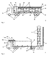
- Fig. 1 shows a side view 2 on a test assembly on a transport device 32, 34 which is movable on wheels 50 - a truck with semi-trailer.
- a cuboid container 16 which is connected to the semi-trailer 32 is designed as a container in this example. For purposes of illustration, a side wall of the container 16 is not shown, so that the components contained in it are visible in the figure.
- a surge generator 12 is disposed in a horizontal position within the container 16.
- a first Base 20 connected to this, which serves in a later vertical position, in particular as a base.
- a voltage divider 14 is arranged above this.
- both components abut each other at a common contact surface, so that the load of the voltage divider 14 in a horizontal position - possibly also using spacers - is removed from the surge voltage generator 12, the load is in turn removed from several spacers 30 on the surface of the container bottom ,
- the voltage divider 14 is connected at its second end to a second base 22, which in turn is connected to the first base 20 by means of a telescopic rail not visible in this illustration. Both pedestals 20, 22 are also connected to the rear end wall 48 of the container 16. Stossbondsgenerator 12, voltage divider 14 and rear end wall 48 are pivotally mounted about a common axis of rotation 18.
- an internal region 26 is separated by means of a partition wall 24, within which measurement and evaluation devices 28 are accommodated.
- This measuring space preferably also serves as a working space for the staff entrusted with the surge voltage test.
- the upper container side is provided with a cover 38 which is composed of a plurality of individual cover segments and is preferably formed of the same material as the side walls of the container, for example steel.
- Fig. 2 shows a side view 4 on the same test arrangement with identical reference numerals as in Fig. 1 ,
- the surge voltage generator 12 and the voltage divider 14 are now shown in a vertical position, which is suitable to perform a surge test.
- a component to be tested for example a power transformer, and electrical connections leading to it are not shown in this figure. All electrical connections between the container 16 arranged on the components 12, 14, 28 are also not shown.
- a rear wall segment 40 of a container side which is moved about a folding axis 42 perpendicular to the remaining outer container wall.
- the rear portion of the container side is thus free and it is a sufficiently high isolation distance to the erected surge voltage generator 12 is reached.
- a support device 44 is mounted, which supports the wall segment relative to the standing surface of the trailer 32.
- Such a foldable wall segment 40 with supporting device 44 is provided on both sides of the container 16. A tilting of the container is prevented.
- cover 38 is now in the form of several superposed cover segments 38a, 38b, 38c and 38d located in the region of the front end of the container 16 and the container is now open at its upper side.
- a corresponding opening movement includes both sliding and folding movements of the cover segments 38a, 38b, 38c and 38d.
- surge voltage generator 12 and voltage divider 14 are pivotable about the axis of rotation 18.
- Fig. 3 shows the top view on the same arrangement as in Fig. 2 represented by the same reference numerals. Particularly clearly visible in this illustration, the support function of the unfolded wall segments 40 with support device 44th
Landscapes
- Physics & Mathematics (AREA)
- General Physics & Mathematics (AREA)
- Engineering & Computer Science (AREA)
- Computer Hardware Design (AREA)
- Microelectronics & Electronic Packaging (AREA)
- General Engineering & Computer Science (AREA)
- Testing Relating To Insulation (AREA)
- Testing Electric Properties And Detecting Electric Faults (AREA)
Claims (15)
- Arrangement d'essai mobile (2, 4, 6) pour les essais de tension de choc de composants électriques à haute tension, comprenant- un générateur de tension de choc (12) et- un diviseur de tension (14),- le générateur de tension de choc (12) et/ou le diviseur de tension (14) pouvant être pivotés d'une première position à chaque fois approximativement horizontale dans une position à chaque fois approximativement verticale, ainsi que- des dispositifs de mesure (28) et des dispositifs d'interprétation (28),- le générateur de tension de choc (12) étant configuré sous la forme d'une structure similaire à une tour qui présente à chaque fois une première extrémité de structure avant et une deuxième extrémité de structure arrière,
caractérisé en ce que- l'arrangement d'essai mobile présente un axe de pivotement disposé sur l'extrémité de structure arrière et un récipient de forme parallélépipédique, en ce que- le générateur de tension de choc (12) et le diviseur de tension (14) ainsi que les dispositifs de mesure (28) et les dispositifs d'interprétation (28) sont disposés ensemble à l'intérieur du récipient de forme parallélépipédique (16), lequel est relié à un dispositif de transport (32, 34) qui présente des roues (50) qui le portent, et en ce que- le générateur de tension de choc (12) et le diviseur de tension (14) peuvent être orientés conjointement autour d'un axe de pivotement disposé sur l'extrémité de structure arrière transversalement à l'axe longitudinal de la structure. - Arrangement d'essai selon la revendication 1, caractérisé en ce que le récipient (16) présente à sa première extrémité une zone intérieure (26) dans laquelle sont disposés les dispositifs de mesure (28) et/ou les dispositifs d'interprétation (28).
- Arrangement d'essai selon l'une des revendications précédentes, caractérisé en ce que le récipient (16) est un conteneur transportable qui est délimité en chacun de ses six côtés au moins partiellement par des parois (38, 48) ou des segments de paroi (38a, 38b, 38c, 38d, 40).
- Arrangement d'essai selon la revendication 3, caractérisé en ce que le conteneur est réalisé sous la forme d'un conteneur de 40 pieds.
- Arrangement d'essai selon la revendication 3 ou 4, caractérisé en ce que le conteneur est homologué selon CSC.
- Arrangement d'essai selon l'une des revendications précédentes, caractérisé en ce que le générateur de tension de choc (12) et le récipient (16) sont reliés entre eux au moyen d'une liaison rotative à leurs deuxièmes extrémités respectives.
- Arrangement d'essai selon l'une des revendications précédentes, caractérisé en ce qu'il est prévu un mécanisme d'entraînement pour réaliser le mouvement de pivotement.
- Arrangement d'essai selon l'une des revendications précédentes, caractérisé en ce qu'au moins une étape de procédé nécessaire pendant une opération d'essai, ou la totalité de l'opération d'essai, peut être initiée au moyen d'une commande à distance.
- Arrangement d'essai selon l'une des revendications précédentes, caractérisé en ce que le récipient (16) peut être fermé sur son côté supérieur par au moins un couvercle amovible (38, 38a, 38b, 38c, 38d).
- Arrangement d'essai selon la revendication 9, caractérisé en ce que le générateur de tension de choc (12) et le diviseur de tension (14) peuvent être pivotés à travers une ouverture sur le côté supérieur du récipient (16), ladite ouverture résultant d'un déplacement du couvercle (38, 38a, 38b, 38c, 38d) dans une position finale.
- Arrangement d'essai selon l'une des revendications précédentes, caractérisé en ce que le récipient (16) est délimité à ses deux surfaces latérales à sa deuxième extrémité au moins partiellement à chaque fois par au moins une paroi ou un segment de paroi (40), lequel peut être déplacé entre une position d'ouverture et une position de fermeture.
- Arrangement d'essai selon la revendication 11, caractérisé en ce que le récipient est bloqué contre un basculement à chaque fois par l'au moins une paroi ou à chaque fois par l'au moins un segment de paroi (40) dans sa position d'ouverture respective.
- Arrangement d'essai selon l'une des revendications précédentes, caractérisé en ce que le générateur de tension de choc est relié par adhérence et/ou par engagement géométrique à la paroi frontale (48) concernée à la deuxième extrémité du récipient et peut pivoter conjointement avec celle-ci autour de l'axe de rotation (18).
- Arrangement d'essai selon l'une des revendications précédentes, caractérisé en ce que le diviseur de tension et le générateur de tension de choc sont reliés entre eux au moyen d'un dispositif de déplacement positionnable en longueur et agissant transversalement à leurs axes longitudinaux parallèles.
- Arrangement d'essai selon l'une des revendications précédentes, caractérisé en ce que le diviseur de tension est intégré à l'intérieur d'une colonne de soutien du générateur de tension de choc, laquelle est formée par plusieurs tubes isolants disposés les uns derrière les autres le long de la structure similaire à une tour.
Priority Applications (19)
| Application Number | Priority Date | Filing Date | Title |
|---|---|---|---|
| EP11004437A EP2378302B1 (fr) | 2008-06-12 | 2008-06-12 | Dispositif d'essai pour des composants électriques à haute tension par tension de choc |
| DE200820016238 DE202008016238U1 (de) | 2008-06-12 | 2008-06-12 | Prüfanordnung |
| ES08010755T ES2374957T3 (es) | 2008-06-12 | 2008-06-12 | Dispositivo de prueba para el ensayo de tensión transitoria de componentes eléctricos de alta tensión. |
| EP08010755A EP2133703B1 (fr) | 2008-06-12 | 2008-06-12 | Dispositif d'essai pour des composants électriques à haute tension par tension de choc |
| AT08010755T ATE528653T1 (de) | 2008-06-12 | 2008-06-12 | Prüfanordnung zur stossspannungsprüfung von elektrischen hochspannungskomponenten |
| RU2011100161/28A RU2505829C2 (ru) | 2008-06-12 | 2009-06-04 | Испытательная система для проверки импульсным напряжением электрических высоковольтных компонентов |
| AU2009256926A AU2009256926B2 (en) | 2008-06-12 | 2009-06-04 | Test arrangement for testing surge voltage in electrical high voltage components |
| CA2725901A CA2725901C (fr) | 2008-06-12 | 2009-06-04 | Systeme d'essai permettant l'essai a la tension de choc de composants electriques a haute tension |
| UAA201014836A UA105180C2 (ru) | 2008-06-12 | 2009-06-04 | Испытательная установка для испытания импульсным напряжением электрических высоковольтных компонентов |
| PCT/EP2009/003976 WO2009149856A1 (fr) | 2008-06-12 | 2009-06-04 | Système d'essai permettant l'essai à la tension de choc de composants électriques à haute tension |
| BRPI0915209A BRPI0915209A8 (pt) | 2008-06-12 | 2009-06-04 | Arranjo de teste para testar pulso de tensão de componentes elétricos de alta tensão |
| CN200980122429.5A CN102057285B (zh) | 2008-06-12 | 2009-06-04 | 用于电高压元件的冲击电压测试的测试布置 |
| PCT/EP2009/004048 WO2009149872A1 (fr) | 2008-06-12 | 2009-06-05 | Système de contrôle pour contrôler la tension de choc de composants a haute tension électrique |
| BRPI0915363A BRPI0915363B1 (pt) | 2008-06-12 | 2009-06-05 | arranjo de teste para teste de tensão de impulso de componentes elétricos de alta tensão |
| EP09761435A EP2286255B1 (fr) | 2008-06-12 | 2009-06-05 | Dispositif d'essai pour des composants électriques à haute tension par tension de choc |
| AT09761435T ATE522818T1 (de) | 2008-06-12 | 2009-06-05 | Prüfanordnung zur stossspannungsprüfung von elektrischen hochspannungskomponenten |
| ARP090102142A AR072127A1 (es) | 2008-06-12 | 2009-06-12 | Disposicion de ensayo |
| US12/961,094 US8502543B2 (en) | 2008-06-12 | 2010-12-06 | Test configuration for the impulse voltage test of electric high-voltage components |
| US12/961,988 US8487637B2 (en) | 2008-06-12 | 2010-12-07 | Test arrangement for impulse voltage testing of electrical high-voltage components |
Applications Claiming Priority (1)
| Application Number | Priority Date | Filing Date | Title |
|---|---|---|---|
| EP08010755A EP2133703B1 (fr) | 2008-06-12 | 2008-06-12 | Dispositif d'essai pour des composants électriques à haute tension par tension de choc |
Related Child Applications (2)
| Application Number | Title | Priority Date | Filing Date |
|---|---|---|---|
| EP11004437A Division EP2378302B1 (fr) | 2008-06-12 | 2008-06-12 | Dispositif d'essai pour des composants électriques à haute tension par tension de choc |
| EP11004437.7 Division-Into | 2011-05-31 |
Publications (2)
| Publication Number | Publication Date |
|---|---|
| EP2133703A1 EP2133703A1 (fr) | 2009-12-16 |
| EP2133703B1 true EP2133703B1 (fr) | 2011-10-12 |
Family
ID=39967961
Family Applications (3)
| Application Number | Title | Priority Date | Filing Date |
|---|---|---|---|
| EP11004437A Not-in-force EP2378302B1 (fr) | 2008-06-12 | 2008-06-12 | Dispositif d'essai pour des composants électriques à haute tension par tension de choc |
| EP08010755A Not-in-force EP2133703B1 (fr) | 2008-06-12 | 2008-06-12 | Dispositif d'essai pour des composants électriques à haute tension par tension de choc |
| EP09761435A Not-in-force EP2286255B1 (fr) | 2008-06-12 | 2009-06-05 | Dispositif d'essai pour des composants électriques à haute tension par tension de choc |
Family Applications Before (1)
| Application Number | Title | Priority Date | Filing Date |
|---|---|---|---|
| EP11004437A Not-in-force EP2378302B1 (fr) | 2008-06-12 | 2008-06-12 | Dispositif d'essai pour des composants électriques à haute tension par tension de choc |
Family Applications After (1)
| Application Number | Title | Priority Date | Filing Date |
|---|---|---|---|
| EP09761435A Not-in-force EP2286255B1 (fr) | 2008-06-12 | 2009-06-05 | Dispositif d'essai pour des composants électriques à haute tension par tension de choc |
Country Status (12)
| Country | Link |
|---|---|
| US (2) | US8502543B2 (fr) |
| EP (3) | EP2378302B1 (fr) |
| CN (1) | CN102057285B (fr) |
| AR (1) | AR072127A1 (fr) |
| AT (2) | ATE528653T1 (fr) |
| AU (1) | AU2009256926B2 (fr) |
| BR (2) | BRPI0915209A8 (fr) |
| CA (1) | CA2725901C (fr) |
| ES (1) | ES2374957T3 (fr) |
| RU (1) | RU2505829C2 (fr) |
| UA (1) | UA105180C2 (fr) |
| WO (2) | WO2009149856A1 (fr) |
Families Citing this family (19)
| Publication number | Priority date | Publication date | Assignee | Title |
|---|---|---|---|---|
| EP2485313B1 (fr) * | 2009-09-30 | 2021-11-24 | Dai Nippon Printing Co., Ltd. | Appareil de contrôle de rupture d'isolation, procédé de contrôle de rupture d'isolation l'utilisant et procédé de fabrication d'une cellule électrochimique |
| CN102285333B (zh) * | 2011-07-13 | 2012-10-03 | 苏州华电电气股份有限公司 | 超高压电力互感器校验车 |
| EP2590185B1 (fr) * | 2011-11-02 | 2014-04-02 | ABB Technology AG | Module de transformateur haute tension |
| US20130176046A1 (en) * | 2012-01-05 | 2013-07-11 | General Electric Company | Mobile transformer testing system |
| CN102901917B (zh) * | 2012-10-22 | 2015-04-01 | 云南电力试验研究院(集团)有限公司电力研究院 | 一种陡前沿脉冲的现场生成装置 |
| CN102955109B (zh) * | 2012-11-15 | 2014-11-26 | 云南电力试验研究院(集团)有限公司电力研究院 | 一种用于便携式冲击电压发生器组装运输试验平台的装置 |
| US9664716B1 (en) | 2013-03-15 | 2017-05-30 | Meg-Alert, Inc. | Automatic insulation resistance testers |
| CN103278750A (zh) * | 2013-04-25 | 2013-09-04 | 国家电网公司 | 陡前沿冲击电压现场gis试验装置 |
| DE102013111018A1 (de) * | 2013-10-04 | 2015-04-09 | Abb Technology Ag | Trägerstruktur für Leistungselektronik |
| EP2863236B1 (fr) * | 2013-10-18 | 2019-12-04 | ABB Schweiz AG | Système de contrôle pour composants haute tension |
| CN103969616B (zh) * | 2014-05-21 | 2016-08-24 | 山东泰开高压开关有限公司 | 用于电子式互感器的型式试验装置 |
| CN105588959A (zh) * | 2016-03-04 | 2016-05-18 | 云南电网有限责任公司电力科学研究院 | 一种可移动冲击电流发生器及使用方法 |
| CN105842597B (zh) * | 2016-06-02 | 2019-05-24 | 国家电网公司 | 一体式冲击电压发生器的车载移动试验平台 |
| RU2621479C1 (ru) * | 2016-07-13 | 2017-06-06 | Общество с ограниченной ответственностью "Аналиттехприбор" | Установка для испытания изоляции объектов электротехнического назначения |
| CN108761216B (zh) * | 2018-07-24 | 2020-12-08 | 深圳市勘察研究院有限公司 | 闪电下劈位置探测装置 |
| CN110501549B (zh) * | 2019-07-19 | 2021-08-17 | 武汉大学 | 一种塔身冲击高电压的测量方法 |
| US11225808B2 (en) | 2020-05-11 | 2022-01-18 | Electric Power Research Institute, Inc. | Emergency restoration system and method |
| US11855470B2 (en) * | 2021-09-23 | 2023-12-26 | Fluidity Power LLC | Mobile generator charging system and method |
| CN116908631B (zh) * | 2023-07-19 | 2024-08-16 | 苏州华电电气股份有限公司 | 一种集成式冲击试验平台 |
Family Cites Families (20)
| Publication number | Priority date | Publication date | Assignee | Title |
|---|---|---|---|---|
| DE521475C (de) | 1929-03-28 | 1931-03-21 | Koch & Sterzel Akt Ges | Transformator, insbesondere Messwandler, fuer hohe Spannungen, bestehend aus in Kaskade geschalteten Einzelsystemen mit in Reihe liegenden Primaerwicklungen und Schub- und UEberkopplungswicklungen |
| US2032904A (en) * | 1935-10-03 | 1936-03-03 | Westinghouse Electric & Mfg Co | Lightning-stroke generator |
| US2237812A (en) | 1940-02-23 | 1941-04-08 | Gen Electric | Portable unit substation |
| US2551841A (en) | 1946-11-27 | 1951-05-08 | Westinghouse Electric Corp | Electrical apparatus |
| US2905891A (en) * | 1957-03-18 | 1959-09-22 | Moloney Electric Company | Electrical testing apparatus |
| DE1563442A1 (de) | 1966-12-08 | 1970-04-02 | Siemens Ag | Kurzschlussdrosselspule |
| DE2328375C3 (de) | 1973-06-04 | 1978-12-14 | Transformatoren Union Ag, 7000 Stuttgart | Kondensatorbatterie zur Spannungssteuerung an Wicklungen von Transformatoren und Drosseln |
| AT330887B (de) | 1974-11-08 | 1976-07-26 | Leinweber Anstalt Ing Joh | Vorrichtung zum pressen von gekrümmten bremsbelägen |
| JPS5936091Y2 (ja) | 1978-11-24 | 1984-10-05 | 株式会社明電舎 | 移動用変電設備 |
| US4427898A (en) | 1981-12-22 | 1984-01-24 | Mitsubishi Denki Kabushiki Kaisha | Mobile power station apparatus |
| JPS58177915U (ja) | 1982-05-20 | 1983-11-28 | 三菱電機株式会社 | 移動用電気装置 |
| SU1179234A1 (ru) * | 1983-08-19 | 1985-09-15 | Проектно-конструкторское бюро электрогидравлики АН УССР | Устройство дл возбуждени сейсмических волн |
| JPS61102176A (ja) * | 1984-10-24 | 1986-05-20 | Kansai Electric Power Co Inc:The | インパルス電圧発生装置 |
| JPS6319570A (ja) * | 1986-07-11 | 1988-01-27 | Hitachi Ltd | ガス絶縁機器の試験方法 |
| RU2083824C1 (ru) * | 1995-06-13 | 1997-07-10 | Научно-исследовательский институт высоких напряжений при Томском политехническом университете | Способ разрушения горных пород |
| DE19639023A1 (de) * | 1996-09-23 | 1998-03-26 | Haefely Trench Ag | Impulsspannungsgeneratorschaltung |
| WO2002051007A1 (fr) * | 2000-12-20 | 2002-06-27 | Haefely Test Ag | Structure de cheminee porteuse pour generateur d'impulsions electriques |
| US6586697B1 (en) * | 2002-07-26 | 2003-07-01 | Pauwels Contracting Inc. | Transportable electrical switching assembly with high voltage circuit interrupter |
| EP2133704B2 (fr) | 2008-06-12 | 2015-12-02 | ABB Technology AG | Dispositif d'essai pour des composants électriques à haute tension par courant alternatif |
| DE202009001837U1 (de) * | 2009-02-13 | 2009-04-16 | Fachhochschule Flensburg | Mobiler Norm-Blitzstoßspannungsgenerator |
-
2008
- 2008-06-12 AT AT08010755T patent/ATE528653T1/de active
- 2008-06-12 EP EP11004437A patent/EP2378302B1/fr not_active Not-in-force
- 2008-06-12 ES ES08010755T patent/ES2374957T3/es active Active
- 2008-06-12 EP EP08010755A patent/EP2133703B1/fr not_active Not-in-force
-
2009
- 2009-06-04 RU RU2011100161/28A patent/RU2505829C2/ru not_active IP Right Cessation
- 2009-06-04 CN CN200980122429.5A patent/CN102057285B/zh not_active Expired - Fee Related
- 2009-06-04 BR BRPI0915209A patent/BRPI0915209A8/pt not_active Application Discontinuation
- 2009-06-04 UA UAA201014836A patent/UA105180C2/ru unknown
- 2009-06-04 CA CA2725901A patent/CA2725901C/fr not_active Expired - Fee Related
- 2009-06-04 WO PCT/EP2009/003976 patent/WO2009149856A1/fr not_active Ceased
- 2009-06-04 AU AU2009256926A patent/AU2009256926B2/en not_active Ceased
- 2009-06-05 AT AT09761435T patent/ATE522818T1/de active
- 2009-06-05 EP EP09761435A patent/EP2286255B1/fr not_active Not-in-force
- 2009-06-05 BR BRPI0915363A patent/BRPI0915363B1/pt not_active IP Right Cessation
- 2009-06-05 WO PCT/EP2009/004048 patent/WO2009149872A1/fr not_active Ceased
- 2009-06-12 AR ARP090102142A patent/AR072127A1/es not_active Application Discontinuation
-
2010
- 2010-12-06 US US12/961,094 patent/US8502543B2/en active Active
- 2010-12-07 US US12/961,988 patent/US8487637B2/en active Active
Also Published As
| Publication number | Publication date |
|---|---|
| UA105180C2 (ru) | 2014-04-25 |
| AU2009256926A1 (en) | 2009-12-17 |
| EP2286255A1 (fr) | 2011-02-23 |
| BRPI0915363A8 (pt) | 2017-12-26 |
| BRPI0915363A2 (pt) | 2015-11-03 |
| CN102057285A (zh) | 2011-05-11 |
| US20110133754A1 (en) | 2011-06-09 |
| AR072127A1 (es) | 2010-08-04 |
| BRPI0915209A8 (pt) | 2017-12-26 |
| RU2505829C2 (ru) | 2014-01-27 |
| EP2133703A1 (fr) | 2009-12-16 |
| CN102057285B (zh) | 2015-04-08 |
| RU2011100161A (ru) | 2012-07-20 |
| EP2378302B1 (fr) | 2012-08-22 |
| ES2374957T3 (es) | 2012-02-23 |
| BRPI0915363B1 (pt) | 2020-02-04 |
| ATE528653T1 (de) | 2011-10-15 |
| CA2725901C (fr) | 2015-11-10 |
| EP2286255B1 (fr) | 2011-08-31 |
| CA2725901A1 (fr) | 2009-12-17 |
| WO2009149856A1 (fr) | 2009-12-17 |
| US8502543B2 (en) | 2013-08-06 |
| AU2009256926B2 (en) | 2013-06-20 |
| WO2009149872A1 (fr) | 2009-12-17 |
| BRPI0915209A2 (pt) | 2016-02-16 |
| ATE522818T1 (de) | 2011-09-15 |
| US20110109319A1 (en) | 2011-05-12 |
| EP2378302A1 (fr) | 2011-10-19 |
| US8487637B2 (en) | 2013-07-16 |
Similar Documents
| Publication | Publication Date | Title |
|---|---|---|
| EP2133703B1 (fr) | Dispositif d'essai pour des composants électriques à haute tension par tension de choc | |
| EP2133704B1 (fr) | Dispositif d'essai pour des composants électriques à haute tension par courant alternatif | |
| DE102009023713A1 (de) | Vorrichtung zur Prüfung von Geräten der Hochspannungstechnik | |
| EP2756320A1 (fr) | Procédé d'identification d'une ou plusieurs sources de décharge partielle apparaissant simultanément | |
| EP2863236B1 (fr) | Système de contrôle pour composants haute tension | |
| EP2859374B1 (fr) | Dispositif pour calibrer un système de mesure de puissance pour des transformateurs de puissance | |
| DE202008016238U1 (de) | Prüfanordnung | |
| EP2133889A1 (fr) | Bobine d'arrêt et agencement de vérification comportant la bobine d'arrêt | |
| DE102011053361A1 (de) | Vorrichtung zur Auswahl eines Stromabnehmers eines Schienenfahrzeugs sowie Verfahren zum kontaktlosen Erkennen eines Spannungssystems | |
| DE202022105380U1 (de) | Messgeräteanordnung zur Funktionsprüfung an elektrischen Leitungen sowie Fahrzeug mit Messgeräteanordnung | |
| EP4105667B1 (fr) | Procédé de mesure de la décharge partielle d'au moins un câble moyenne tension d'un réseau moyenne tension | |
| DE19725611C2 (de) | Überwachungsverfahren und Überwachungsgerät für ein Kabel | |
| DE3738065C2 (fr) | ||
| DE3011619C2 (de) | Schaltgeräteschrank für transportable Siganlanlagen | |
| WO2014009084A1 (fr) | Agencement de composants d'un diviseur de tension adapté en fonction du champ électrique | |
| DE7739092U1 (de) | Geraet zum ueberpruefen der funktion von zuendanlagen und deren bestandteilen an otto-motoren | |
| EP2887045B1 (fr) | Installation d'entrelacement | |
| DE102021120050A1 (de) | Mobile elektrische Energiebereitstellungsvorrichtung | |
| WO2009149865A1 (fr) | Module de générateur de tension de choc et générateur de tension de choc | |
| DE1008400B (de) | Einrichtung zur Erzeugung von Stossspannungen fuer Pruefzwecke |
Legal Events
| Date | Code | Title | Description |
|---|---|---|---|
| PUAI | Public reference made under article 153(3) epc to a published international application that has entered the european phase |
Free format text: ORIGINAL CODE: 0009012 |
|
| AK | Designated contracting states |
Kind code of ref document: A1 Designated state(s): AT BE BG CH CY CZ DE DK EE ES FI FR GB GR HR HU IE IS IT LI LT LU LV MC MT NL NO PL PT RO SE SI SK TR |
|
| AX | Request for extension of the european patent |
Extension state: AL BA MK RS |
|
| AKX | Designation fees paid |
Designated state(s): AT BE BG CH CY CZ DE DK EE ES FI FR GB GR HR HU IE IS IT LI LT LU LV MC MT NL NO PL PT RO SE SI SK TR |
|
| 17P | Request for examination filed |
Effective date: 20100903 |
|
| 17Q | First examination report despatched |
Effective date: 20101027 |
|
| RIN1 | Information on inventor provided before grant (corrected) |
Inventor name: WERLE,PETER Inventor name: STEIGER, MATTHIAS |
|
| GRAP | Despatch of communication of intention to grant a patent |
Free format text: ORIGINAL CODE: EPIDOSNIGR1 |
|
| RTI1 | Title (correction) |
Free format text: TEST ASSEMBLY FOR SURGE VOLTAGE TESTING OF HIGH VOLTAGE ELECTRICAL COMPONENTS |
|
| RIN1 | Information on inventor provided before grant (corrected) |
Inventor name: MATTHIAS STEIGER Inventor name: WERLE, PETER |
|
| GRAS | Grant fee paid |
Free format text: ORIGINAL CODE: EPIDOSNIGR3 |
|
| GRAA | (expected) grant |
Free format text: ORIGINAL CODE: 0009210 |
|
| AK | Designated contracting states |
Kind code of ref document: B1 Designated state(s): AT BE BG CH CY CZ DE DK EE ES FI FR GB GR HR HU IE IS IT LI LT LU LV MC MT NL NO PL PT RO SE SI SK TR |
|
| REG | Reference to a national code |
Ref country code: GB Ref legal event code: FG4D Free format text: NOT ENGLISH |
|
| REG | Reference to a national code |
Ref country code: CH Ref legal event code: EP |
|
| REG | Reference to a national code |
Ref country code: IE Ref legal event code: FG4D |
|
| REG | Reference to a national code |
Ref country code: DE Ref legal event code: R096 Ref document number: 502008005116 Country of ref document: DE Effective date: 20111208 |
|
| REG | Reference to a national code |
Ref country code: NL Ref legal event code: VDEP Effective date: 20111012 |
|
| REG | Reference to a national code |
Ref country code: ES Ref legal event code: FG2A Ref document number: 2374957 Country of ref document: ES Kind code of ref document: T3 Effective date: 20120223 |
|
| LTIE | Lt: invalidation of european patent or patent extension |
Effective date: 20111012 |
|
| PG25 | Lapsed in a contracting state [announced via postgrant information from national office to epo] |
Ref country code: NO Free format text: LAPSE BECAUSE OF FAILURE TO SUBMIT A TRANSLATION OF THE DESCRIPTION OR TO PAY THE FEE WITHIN THE PRESCRIBED TIME-LIMIT Effective date: 20120112 Ref country code: IS Free format text: LAPSE BECAUSE OF FAILURE TO SUBMIT A TRANSLATION OF THE DESCRIPTION OR TO PAY THE FEE WITHIN THE PRESCRIBED TIME-LIMIT Effective date: 20120212 Ref country code: LT Free format text: LAPSE BECAUSE OF FAILURE TO SUBMIT A TRANSLATION OF THE DESCRIPTION OR TO PAY THE FEE WITHIN THE PRESCRIBED TIME-LIMIT Effective date: 20111012 |
|
| REG | Reference to a national code |
Ref country code: IE Ref legal event code: FD4D |
|
| PG25 | Lapsed in a contracting state [announced via postgrant information from national office to epo] |
Ref country code: SE Free format text: LAPSE BECAUSE OF FAILURE TO SUBMIT A TRANSLATION OF THE DESCRIPTION OR TO PAY THE FEE WITHIN THE PRESCRIBED TIME-LIMIT Effective date: 20111012 Ref country code: GR Free format text: LAPSE BECAUSE OF FAILURE TO SUBMIT A TRANSLATION OF THE DESCRIPTION OR TO PAY THE FEE WITHIN THE PRESCRIBED TIME-LIMIT Effective date: 20120113 Ref country code: SI Free format text: LAPSE BECAUSE OF FAILURE TO SUBMIT A TRANSLATION OF THE DESCRIPTION OR TO PAY THE FEE WITHIN THE PRESCRIBED TIME-LIMIT Effective date: 20111012 Ref country code: HR Free format text: LAPSE BECAUSE OF FAILURE TO SUBMIT A TRANSLATION OF THE DESCRIPTION OR TO PAY THE FEE WITHIN THE PRESCRIBED TIME-LIMIT Effective date: 20111012 Ref country code: NL Free format text: LAPSE BECAUSE OF FAILURE TO SUBMIT A TRANSLATION OF THE DESCRIPTION OR TO PAY THE FEE WITHIN THE PRESCRIBED TIME-LIMIT Effective date: 20111012 Ref country code: PT Free format text: LAPSE BECAUSE OF FAILURE TO SUBMIT A TRANSLATION OF THE DESCRIPTION OR TO PAY THE FEE WITHIN THE PRESCRIBED TIME-LIMIT Effective date: 20120213 Ref country code: LV Free format text: LAPSE BECAUSE OF FAILURE TO SUBMIT A TRANSLATION OF THE DESCRIPTION OR TO PAY THE FEE WITHIN THE PRESCRIBED TIME-LIMIT Effective date: 20111012 |
|
| PG25 | Lapsed in a contracting state [announced via postgrant information from national office to epo] |
Ref country code: CY Free format text: LAPSE BECAUSE OF FAILURE TO SUBMIT A TRANSLATION OF THE DESCRIPTION OR TO PAY THE FEE WITHIN THE PRESCRIBED TIME-LIMIT Effective date: 20111012 |
|
| PG25 | Lapsed in a contracting state [announced via postgrant information from national office to epo] |
Ref country code: DK Free format text: LAPSE BECAUSE OF FAILURE TO SUBMIT A TRANSLATION OF THE DESCRIPTION OR TO PAY THE FEE WITHIN THE PRESCRIBED TIME-LIMIT Effective date: 20111012 Ref country code: CZ Free format text: LAPSE BECAUSE OF FAILURE TO SUBMIT A TRANSLATION OF THE DESCRIPTION OR TO PAY THE FEE WITHIN THE PRESCRIBED TIME-LIMIT Effective date: 20111012 Ref country code: EE Free format text: LAPSE BECAUSE OF FAILURE TO SUBMIT A TRANSLATION OF THE DESCRIPTION OR TO PAY THE FEE WITHIN THE PRESCRIBED TIME-LIMIT Effective date: 20111012 Ref country code: IE Free format text: LAPSE BECAUSE OF FAILURE TO SUBMIT A TRANSLATION OF THE DESCRIPTION OR TO PAY THE FEE WITHIN THE PRESCRIBED TIME-LIMIT Effective date: 20111012 Ref country code: BG Free format text: LAPSE BECAUSE OF FAILURE TO SUBMIT A TRANSLATION OF THE DESCRIPTION OR TO PAY THE FEE WITHIN THE PRESCRIBED TIME-LIMIT Effective date: 20120112 Ref country code: SK Free format text: LAPSE BECAUSE OF FAILURE TO SUBMIT A TRANSLATION OF THE DESCRIPTION OR TO PAY THE FEE WITHIN THE PRESCRIBED TIME-LIMIT Effective date: 20111012 |
|
| PLBE | No opposition filed within time limit |
Free format text: ORIGINAL CODE: 0009261 |
|
| STAA | Information on the status of an ep patent application or granted ep patent |
Free format text: STATUS: NO OPPOSITION FILED WITHIN TIME LIMIT |
|
| PG25 | Lapsed in a contracting state [announced via postgrant information from national office to epo] |
Ref country code: RO Free format text: LAPSE BECAUSE OF FAILURE TO SUBMIT A TRANSLATION OF THE DESCRIPTION OR TO PAY THE FEE WITHIN THE PRESCRIBED TIME-LIMIT Effective date: 20111012 Ref country code: PL Free format text: LAPSE BECAUSE OF FAILURE TO SUBMIT A TRANSLATION OF THE DESCRIPTION OR TO PAY THE FEE WITHIN THE PRESCRIBED TIME-LIMIT Effective date: 20111012 |
|
| 26N | No opposition filed |
Effective date: 20120713 |
|
| REG | Reference to a national code |
Ref country code: DE Ref legal event code: R097 Ref document number: 502008005116 Country of ref document: DE Effective date: 20120713 |
|
| BERE | Be: lapsed |
Owner name: ABB TECHNOLOGY A.G. Effective date: 20120630 |
|
| PG25 | Lapsed in a contracting state [announced via postgrant information from national office to epo] |
Ref country code: MC Free format text: LAPSE BECAUSE OF NON-PAYMENT OF DUE FEES Effective date: 20120630 |
|
| REG | Reference to a national code |
Ref country code: CH Ref legal event code: PL |
|
| REG | Reference to a national code |
Ref country code: CH Ref legal event code: PL |
|
| PG25 | Lapsed in a contracting state [announced via postgrant information from national office to epo] |
Ref country code: LI Free format text: LAPSE BECAUSE OF NON-PAYMENT OF DUE FEES Effective date: 20120630 Ref country code: CH Free format text: LAPSE BECAUSE OF NON-PAYMENT OF DUE FEES Effective date: 20120630 Ref country code: BE Free format text: LAPSE BECAUSE OF NON-PAYMENT OF DUE FEES Effective date: 20120630 |
|
| PG25 | Lapsed in a contracting state [announced via postgrant information from national office to epo] |
Ref country code: FI Free format text: LAPSE BECAUSE OF FAILURE TO SUBMIT A TRANSLATION OF THE DESCRIPTION OR TO PAY THE FEE WITHIN THE PRESCRIBED TIME-LIMIT Effective date: 20111012 |
|
| PG25 | Lapsed in a contracting state [announced via postgrant information from national office to epo] |
Ref country code: MT Free format text: LAPSE BECAUSE OF FAILURE TO SUBMIT A TRANSLATION OF THE DESCRIPTION OR TO PAY THE FEE WITHIN THE PRESCRIBED TIME-LIMIT Effective date: 20111012 |
|
| PG25 | Lapsed in a contracting state [announced via postgrant information from national office to epo] |
Ref country code: TR Free format text: LAPSE BECAUSE OF FAILURE TO SUBMIT A TRANSLATION OF THE DESCRIPTION OR TO PAY THE FEE WITHIN THE PRESCRIBED TIME-LIMIT Effective date: 20111012 |
|
| PG25 | Lapsed in a contracting state [announced via postgrant information from national office to epo] |
Ref country code: LU Free format text: LAPSE BECAUSE OF NON-PAYMENT OF DUE FEES Effective date: 20120612 |
|
| PG25 | Lapsed in a contracting state [announced via postgrant information from national office to epo] |
Ref country code: HU Free format text: LAPSE BECAUSE OF FAILURE TO SUBMIT A TRANSLATION OF THE DESCRIPTION OR TO PAY THE FEE WITHIN THE PRESCRIBED TIME-LIMIT Effective date: 20080612 |
|
| REG | Reference to a national code |
Ref country code: AT Ref legal event code: MM01 Ref document number: 528653 Country of ref document: AT Kind code of ref document: T Effective date: 20130612 |
|
| PG25 | Lapsed in a contracting state [announced via postgrant information from national office to epo] |
Ref country code: AT Free format text: LAPSE BECAUSE OF NON-PAYMENT OF DUE FEES Effective date: 20130612 |
|
| REG | Reference to a national code |
Ref country code: FR Ref legal event code: PLFP Year of fee payment: 8 |
|
| PGFP | Annual fee paid to national office [announced via postgrant information from national office to epo] |
Ref country code: GB Payment date: 20150618 Year of fee payment: 8 Ref country code: DE Payment date: 20150619 Year of fee payment: 8 Ref country code: ES Payment date: 20150626 Year of fee payment: 8 |
|
| PGFP | Annual fee paid to national office [announced via postgrant information from national office to epo] |
Ref country code: IT Payment date: 20150622 Year of fee payment: 8 Ref country code: FR Payment date: 20150619 Year of fee payment: 8 |
|
| REG | Reference to a national code |
Ref country code: DE Ref legal event code: R119 Ref document number: 502008005116 Country of ref document: DE |
|
| GBPC | Gb: european patent ceased through non-payment of renewal fee |
Effective date: 20160612 |
|
| REG | Reference to a national code |
Ref country code: FR Ref legal event code: ST Effective date: 20170228 |
|
| PG25 | Lapsed in a contracting state [announced via postgrant information from national office to epo] |
Ref country code: FR Free format text: LAPSE BECAUSE OF NON-PAYMENT OF DUE FEES Effective date: 20160630 Ref country code: DE Free format text: LAPSE BECAUSE OF NON-PAYMENT OF DUE FEES Effective date: 20170103 |
|
| PG25 | Lapsed in a contracting state [announced via postgrant information from national office to epo] |
Ref country code: GB Free format text: LAPSE BECAUSE OF NON-PAYMENT OF DUE FEES Effective date: 20160612 |
|
| PG25 | Lapsed in a contracting state [announced via postgrant information from national office to epo] |
Ref country code: IT Free format text: LAPSE BECAUSE OF NON-PAYMENT OF DUE FEES Effective date: 20160612 |
|
| PG25 | Lapsed in a contracting state [announced via postgrant information from national office to epo] |
Ref country code: ES Free format text: LAPSE BECAUSE OF NON-PAYMENT OF DUE FEES Effective date: 20160613 |
|
| REG | Reference to a national code |
Ref country code: ES Ref legal event code: FD2A Effective date: 20181203 |