EP2138759A1 - Automotive lamp - Google Patents
Automotive lamp Download PDFInfo
- Publication number
- EP2138759A1 EP2138759A1 EP20090163408 EP09163408A EP2138759A1 EP 2138759 A1 EP2138759 A1 EP 2138759A1 EP 20090163408 EP20090163408 EP 20090163408 EP 09163408 A EP09163408 A EP 09163408A EP 2138759 A1 EP2138759 A1 EP 2138759A1
- Authority
- EP
- European Patent Office
- Prior art keywords
- air
- heatsink
- centrifugal fan
- plate fins
- fins
- Prior art date
- Legal status (The legal status is an assumption and is not a legal conclusion. Google has not performed a legal analysis and makes no representation as to the accuracy of the status listed.)
- Withdrawn
Links
- 238000009423 ventilation Methods 0.000 claims abstract description 52
- 238000001816 cooling Methods 0.000 claims abstract description 29
- 238000007599 discharging Methods 0.000 claims abstract description 9
- 239000004065 semiconductor Substances 0.000 claims description 16
- 230000005855 radiation Effects 0.000 description 11
- 239000000758 substrate Substances 0.000 description 7
- 229910052782 aluminium Inorganic materials 0.000 description 2
- XAGFODPZIPBFFR-UHFFFAOYSA-N aluminium Chemical compound [Al] XAGFODPZIPBFFR-UHFFFAOYSA-N 0.000 description 2
- 238000004519 manufacturing process Methods 0.000 description 2
- 229910052751 metal Inorganic materials 0.000 description 2
- 239000002184 metal Substances 0.000 description 2
- 238000012986 modification Methods 0.000 description 2
- 230000004048 modification Effects 0.000 description 2
- 230000015572 biosynthetic process Effects 0.000 description 1
- 239000000919 ceramic Substances 0.000 description 1
- 239000012141 concentrate Substances 0.000 description 1
- 239000004020 conductor Substances 0.000 description 1
- 238000004512 die casting Methods 0.000 description 1
- 238000010438 heat treatment Methods 0.000 description 1
- 239000000463 material Substances 0.000 description 1
- 238000000034 method Methods 0.000 description 1
- 229920000515 polycarbonate Polymers 0.000 description 1
- 239000004417 polycarbonate Substances 0.000 description 1
- 239000011347 resin Substances 0.000 description 1
- 229920005989 resin Polymers 0.000 description 1
Images

Classifications
-
- F—MECHANICAL ENGINEERING; LIGHTING; HEATING; WEAPONS; BLASTING
- F21—LIGHTING
- F21S—NON-PORTABLE LIGHTING DEVICES; SYSTEMS THEREOF; VEHICLE LIGHTING DEVICES SPECIALLY ADAPTED FOR VEHICLE EXTERIORS
- F21S41/00—Illuminating devices specially adapted for vehicle exteriors, e.g. headlamps
- F21S41/10—Illuminating devices specially adapted for vehicle exteriors, e.g. headlamps characterised by the light source
- F21S41/14—Illuminating devices specially adapted for vehicle exteriors, e.g. headlamps characterised by the light source characterised by the type of light source
- F21S41/141—Light emitting diodes [LED]
- F21S41/147—Light emitting diodes [LED] the main emission direction of the LED being angled to the optical axis of the illuminating device
- F21S41/148—Light emitting diodes [LED] the main emission direction of the LED being angled to the optical axis of the illuminating device the main emission direction of the LED being perpendicular to the optical axis
-
- B—PERFORMING OPERATIONS; TRANSPORTING
- B60—VEHICLES IN GENERAL
- B60Q—ARRANGEMENT OF SIGNALLING OR LIGHTING DEVICES, THE MOUNTING OR SUPPORTING THEREOF OR CIRCUITS THEREFOR, FOR VEHICLES IN GENERAL
- B60Q1/00—Arrangement of optical signalling or lighting devices, the mounting or supporting thereof or circuits therefor
-
- F—MECHANICAL ENGINEERING; LIGHTING; HEATING; WEAPONS; BLASTING
- F21—LIGHTING
- F21S—NON-PORTABLE LIGHTING DEVICES; SYSTEMS THEREOF; VEHICLE LIGHTING DEVICES SPECIALLY ADAPTED FOR VEHICLE EXTERIORS
- F21S45/00—Arrangements within vehicle lighting devices specially adapted for vehicle exteriors, for purposes other than emission or distribution of light
- F21S45/40—Cooling of lighting devices
- F21S45/42—Forced cooling
- F21S45/43—Forced cooling using gas
- F21S45/435—Forced cooling using gas circulating the gas within a closed system
-
- F—MECHANICAL ENGINEERING; LIGHTING; HEATING; WEAPONS; BLASTING
- F21—LIGHTING
- F21V—FUNCTIONAL FEATURES OR DETAILS OF LIGHTING DEVICES OR SYSTEMS THEREOF; STRUCTURAL COMBINATIONS OF LIGHTING DEVICES WITH OTHER ARTICLES, NOT OTHERWISE PROVIDED FOR
- F21V29/00—Protecting lighting devices from thermal damage; Cooling or heating arrangements specially adapted for lighting devices or systems
-
- F—MECHANICAL ENGINEERING; LIGHTING; HEATING; WEAPONS; BLASTING
- F21—LIGHTING
- F21V—FUNCTIONAL FEATURES OR DETAILS OF LIGHTING DEVICES OR SYSTEMS THEREOF; STRUCTURAL COMBINATIONS OF LIGHTING DEVICES WITH OTHER ARTICLES, NOT OTHERWISE PROVIDED FOR
- F21V29/00—Protecting lighting devices from thermal damage; Cooling or heating arrangements specially adapted for lighting devices or systems
- F21V29/50—Cooling arrangements
- F21V29/60—Cooling arrangements characterised by the use of a forced flow of gas, e.g. air
- F21V29/67—Cooling arrangements characterised by the use of a forced flow of gas, e.g. air characterised by the arrangement of fans
-
- F—MECHANICAL ENGINEERING; LIGHTING; HEATING; WEAPONS; BLASTING
- F21—LIGHTING
- F21V—FUNCTIONAL FEATURES OR DETAILS OF LIGHTING DEVICES OR SYSTEMS THEREOF; STRUCTURAL COMBINATIONS OF LIGHTING DEVICES WITH OTHER ARTICLES, NOT OTHERWISE PROVIDED FOR
- F21V29/00—Protecting lighting devices from thermal damage; Cooling or heating arrangements specially adapted for lighting devices or systems
- F21V29/50—Cooling arrangements
- F21V29/70—Cooling arrangements characterised by passive heat-dissipating elements, e.g. heat-sinks
- F21V29/74—Cooling arrangements characterised by passive heat-dissipating elements, e.g. heat-sinks with fins or blades
- F21V29/76—Cooling arrangements characterised by passive heat-dissipating elements, e.g. heat-sinks with fins or blades with essentially identical parallel planar fins or blades, e.g. with comb-like cross-section
- F21V29/763—Cooling arrangements characterised by passive heat-dissipating elements, e.g. heat-sinks with fins or blades with essentially identical parallel planar fins or blades, e.g. with comb-like cross-section the planes containing the fins or blades having the direction of the light emitting axis
-
- F—MECHANICAL ENGINEERING; LIGHTING; HEATING; WEAPONS; BLASTING
- F21—LIGHTING
- F21Y—INDEXING SCHEME ASSOCIATED WITH SUBCLASSES F21K, F21L, F21S and F21V, RELATING TO THE FORM OR THE KIND OF THE LIGHT SOURCES OR OF THE COLOUR OF THE LIGHT EMITTED
- F21Y2115/00—Light-generating elements of semiconductor light sources
- F21Y2115/10—Light-emitting diodes [LED]
Definitions
- An automotive lamp comprises: a semiconductor light emitting device as a light source; a heatsink which radiates heat produced by the semiconductor light emitting device, the heatsink including a plurality of plate fins installed upright on a base part and a plurality of ventilation passages formed between the plate fins; a centrifugal fan which performs a forced air cooling of the plate fins by sending air through the ventilation passages of the heatsink, the centrifugal fan having air inlets open in an axial direction thereof for drawing air in and a plurality of air outlets for discharging air in a plurality of directions perpendicular to the axial direction thereof; and a lamp housing which houses the semiconductor light emitting device, heatsink, and centrifugal fan, wherein the plate fins of the heatsink are forced such that an entrance of at least one of the plurality of ventilation passages faces each of the air outlets of the centrifugal fan.
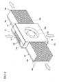
- FIG. 2 is a perspective illustration of a heatsink 14 and a centrifugal fan 56 of an automotive lamp 10 according to the first embodiment of the present invention.
- the heatsink 14 is comprised of a first sub-heatsink 50, a second sub-heatsink 52, and a third sub-heatsink 54,
- the second sub-heatsink 52 is located in the middle, with the first sub-heatsink 50 on the left and the third sub-heatsink 54 on the right facing frontward from the automotive lamp 10.
- the first lamp unit is mounted to the first sub-heatsink 50, the second lamp unit to the second sub-heatsink 52, and the third lamp unit to the third sub-heatsink 54 (first to third lamp units being not shown in FIG. 2 ).
- the air discharged from the left-side air outlet 56c of the centrifugal fan 56 flows through the entrances of the ventilation passages facing the left-side air outlet 56c into the ventilation passages of the first sub-heatsink 50.
- the air whose temperature is raised by the heat radiated from the first plate fins 50b of the first sub-heatsink 50 is discharged from the exits of the ventilation passages as shown in FIG. 2 .
- the air discharged from the right-side air outlet 56d of the centrifugal fan 56 flows through the entrances of the ventilation passages facing the right-side air outlet 56d into the ventilation passages of the third sub-heatsink 54.
- the air whose temperature is raised by the heat radiated from the third plate fins 54b of the third sub-heatsink 54 is discharged from the exits of the ventilation passages as shown in FIG. 2 .
- the automotive lamp 10 is so structured that the second plate fins 52b of the second sub-heatsink 52, which are subjected to forced air cooling by the intake of air caused by the centrifugal fan 56, extend in a direction perpendicular to the direction in which the first plate fins 50b of the first sub-heatsink 50 and the third plate fins 54b of the third sub-heatsink 54, which are subjected to forced air cooling by the discharge of air caused by the centrifugal fan 56, extend. If the air immediately after the discharge goes back to the air inlets of the centrifugal fan, then there will be no active circulation of air inside the lamp chamber, which leads to a drop in heat radiation efficiency. Formation of the plate fins as implemented in the first embodiment can therefor prevent the air immediately after the discharge from going back to the air inlets of the centrifugal fan. And this promotes an active circulation of air inside the lamp chamber, thus improving the heat radiation efficiency.
Landscapes
- Engineering & Computer Science (AREA)
- General Engineering & Computer Science (AREA)
- Physics & Mathematics (AREA)
- Microelectronics & Electronic Packaging (AREA)
- Optics & Photonics (AREA)
- Mechanical Engineering (AREA)
- Arrangement Of Elements, Cooling, Sealing, Or The Like Of Lighting Devices (AREA)
- Non-Portable Lighting Devices Or Systems Thereof (AREA)
Abstract
Description
- The present invention relates to an automotive lamp and, in particular, to an automotive lamp whose light source is a semiconductor light emitting device.
- There are automotive lamps that use a semiconductor light emitting device, such as an LED (light emitting diode) or the like, as the light source. When a semiconductor light emitting device is used as the light source for an automotive lamp, the level of light intensity required of the automotive lamp must be satisfied by a maximum use of the light emission from the semiconductor light emitting device.
- Generally, a semiconductor light emitting device produces more heat for larger current which is supplied to obtain a greater output. And this correspondingly lowers the luminance efficiency of the semiconductor light emitting device as it gets hotter due to the heating. Thus, there have been various heat radiation structures proposed for automotive lamps in order to radiate heat from the semiconductor light emitting device efficiently. An example can be found in Japanese Patent Application Publication No.
2006-286395 - With the automotive lamp as disclosed in Japanese Patent Application Publication No.
2006-286395 - The present invention has been made in view of the foregoing circumstances, and one aim of embodiments thereof is to provide an automotive lamp capable of efficiently transferring heat that is produced by the semiconductor light emitting device.
- An automotive lamp according to one embodiment of the present invention comprises: a semiconductor light emitting device as a light source; a heatsink which radiates heat produced by the semiconductor light emitting device, the heatsink including a plurality of plate fins installed upright on a base part and a plurality of ventilation passages formed between the plate fins; a centrifugal fan which performs a forced air cooling of the plate fins by sending air through the ventilation passages of the heatsink, the centrifugal fan having air inlets open in an axial direction thereof for drawing air in and a plurality of air outlets for discharging air in a plurality of directions perpendicular to the axial direction thereof; and a lamp housing which houses the semiconductor light emitting device, heatsink, and centrifugal fan, wherein the plate fins of the heatsink are forced such that an entrance of at least one of the plurality of ventilation passages faces each of the air outlets of the centrifugal fan.
- Embodiments will now be described by way of example only, with reference to the accompanying drawings which are meant to be exemplary, not limiting and wherein like elements are numbered alike in several Figures in which:
-
FIG, 1 is a schematic cross-sectional view of an automotive lamp according to a first embodiment; -
FIG. 2 is a perspective illustration of a heatsink and a fan of an automotive lamp according to a first embodiment; and -
FIG. 3 is a perspective illustration of a heatsink and a fan of an automotive lamp according to a second embodiment - A detailed description is given hereinbelow of some automotive lamps embodying the invention, with reference to the accompanying drawings.
- As illustrated in
FIG. 1 , theautomotive lamp 10 is of a structure such that alamp unit 30 is housed in a lamp housing which includes alamp body 48 formed of a resin, which is open in the front, and anouter cover 34 formed of a translucent material, which covers the front of thelamp body 48 in an airtight manner. - It is to be noted that although only a
single lamp unit 30 is shown inFIG. 1 , theautomotive lamp 10 houses three lamp units, namely, a first lamp unit, a second lamp unit, and a third lamp unit, within the lamp housing thereof. The first to third lamp units are of an identical structure. The first to third lamp units are installed adjacent to each other left to right in a row. That is, facing the front of theautomotive lamp 10, the first lamp unit is located on the left, the second lamp unit in the middle, and the third lamp unit on the right. Thelamp unit 30 shown inFIG. 1 is the second lamp unit located in the Middle. Hereinbelow, the first to third lamp units, when they are named generically, will simply be referred to as "lamp unit 30". - The
lamp unit 30, which is a so-called projector-type lamp unit, uses an LED as the light source. Eachlamp unit 30 includes anLED 20, a thermally conductiveinsulating substrate 24, areflector 22, amounting member 26, and aprotection lens 32. TheLED 20 is a white-color LED comprising a not-shown LED chip and an approximately hemispherical cap covering the LED chip. TheLED 20 is disposed on the thermally conductiveinsulating substrate 24 which is formed of a ceramic or the like, TheLED 20 is installed in a position on a light axis Ax of thelamp unit 30 such that the light emission direction thereof faces a direction perpendicular to the light axis Ax. Power is supplied to theLED 20 through a wiring pattern formed on the thermallyconductive insulating substrate 24. - The
reflector 22, which is shaped as a half dome made of, for instance, a polycarbonate, is disposed over theLED 20. Thereflector 22 has a reflecting surface on the inside thereof which reflects light from theLED 20 in the front direction in such a manner as to concentrate it toward the light axis Ax. - The
projection lens 32, which is a planoconvex aspheric lens having a convex front surface and a plane rear surface, irradiates the image of the light source formed on the rear focal plane as a reverted image. Themounting member 26 is substantially a flat plate formed of a metal having aluminum as the main component by die casting. And anchored to the upper surface thereof are thesubstrate 24 mounted with theLED 20 and thereflector 22, Also, attached to the front end of themounting member 26 is theprojection lens 32. - The rear end of the
mounting member 26 of eachlamp unit 30 is attached to aheatsink 14 which is provided in alamp chamber 35. Theheats ink 14, which is formed of aluminum or other metal having a high thermal conductivity, radiates heat produced by theLED 20 of eachlamp unit 30 into the air inside thelamp chamber 35. Attached to theheatsink 14 is acentrifugal fan 56. Thecentrifugal fan 56 draws air in from an axial direction and sends air out in centrifugal directions. A detailed description of the structures of theheatsink 14 and thecentrifugal fan 56 will be given with reference toFIG. 2 . - The
lamp unit 30, theheatsink 14 and thecentrifugal fan 56 are installed within thelamp chamber 35 by means of a not-shown support member in such a manner that the light emitted by eachlamp unit 30 can be irradiated frontward from theautomotive lamp 10. In the first embodiment, thelamp unit 30, theheatsink 14 and thecentrifugal fan 56 are installed near the center of thelamp chamber 35. -
FIG. 2 is a perspective illustration of aheatsink 14 and acentrifugal fan 56 of anautomotive lamp 10 according to the first embodiment of the present invention. As shown inFIG. 2 , theheatsink 14 is comprised of afirst sub-heatsink 50, asecond sub-heatsink 52, and athird sub-heatsink 54, In theheatsink 14, thesecond sub-heatsink 52 is located in the middle, with thefirst sub-heatsink 50 on the left and thethird sub-heatsink 54 on the right facing frontward from theautomotive lamp 10. The first lamp unit is mounted to thefirst sub-heatsink 50, the second lamp unit to thesecond sub-heatsink 52, and the third lamp unit to the third sub-heatsink 54 (first to third lamp units being not shown inFIG. 2 ). - The
first sub-heatsink 50 is comprised of afirst base part 50a and a plurality offirst plate fins 50b mounted upright on thefirst base part 50a in parallel with each other at predetermined intervals. Formed between the plurality offirst plate fins 50b are a plurality of ventilation passages in parallel with each other. Also, thesecond sub-heatsink 52 is comprised of asecond base part 52a and a plurality ofsecond plate fins 52b disposed upright on thesecond base part 52a in parallel with each other at predetermined intervals, Formed between the plurality ofsecond plate fins 52b are a plurality of ventilation passages in parallel with each other. Also, thethird sub-heatsink 54 is comprised of athird base part 54a and a plurality ofthird plate fins 54b disposed upright on thethird base part 54a in parallel with each other at predetermined intervals. Formed between the plurality ofthird plate fins 54b are a plurality of ventilation passages in parallel with each other. - The
first base part 50a, thesecond base part 52a and thethird base part 54a are formed by a single plate member. In this manner, forming the first tothird base parts 50a to 54a by a single plate member allows easy handling of the first tothird sub-heatsinks 50 to 54 as a single assembly. As a result, the assembly can be installed on thelamp body 48 with great ease. Alternatively, however, the first tothird base parts 50a to 54a may be formed as separate bodies, in which case the manufacture of the first tothird sub-heatsinks 50 to 54 can be made easier. - In the first embodiment, the first plate fins 50b of the
first sub-heatsink 50 are so formed as to extend in the left-right (horizontal) direction. The direction of extension of the plate fins meant here is the longitudinal direction of the plate fins. Also, thethird plate fins 54b of thethird sub-heatsink 54 are so formed as to extend in the left-right (horizontal) direction. On the other hand, the second plate fins 52b of thesecond sub-heatsink 52, which is located in the middle, are so formed as to extend in the vertical direction. That is, the direction of extension of the plate fins of thesecond sub-heatsink 52 is perpendicular to the direction thereof of thefirst sub-heatsink 50 and thethird sub-heatsink 54. - The first plate fins 50b and the
third plate fins 54b are so formed as to be approximately the same in height from the base part. On the other hand, thesecond plate fins 52b are so formed that the height from the base part thereof is about half that of thefirst plate fins 50b and thethird plate fins 54b. Accordingly, there results a space, between thefirst plate fins 50b and thethird plate fins 54b, recessed as much as thesecond plate fins 52b are lower in height than the first plate fins 50b and the third plate fins 54b. - The
centrifugal fan 56 is installed on thesecond plate fins 52b in such a manner that it fits into the above-mentioned recessed space. Thecentrifugal fan 56 has anair inlet 56a in the front in the axial direction thereof and anair inlet 56b in the rear in the axial direction thereof for drawing air in, anair outlet 56c in the left side thereof for discharging air leftward perpendicular to the axial direction thereof, and anair outlet 56d in the right side thereof for discharging air rightward perpendicular to the axial direction thereof. As power is supplied to a motor (not shown) of thecentrifugal fan 56 and fan blades (not shown) begin rotating, air is drawn in through the axiallyfront air inlet 56a and the axiallyrear air inlet 56b and then discharged leftward and rightward through the left-side air outlet 56c and the right-side air outlet 56d, respectively. - As air is drawn in through the axially
front air inlet 56a, the pressure inside the ventilation passages of thesecond sub-heatsink 52 becomes negative, so that air flows into the ventilation passages between thesecond plate fins 52b from above and below. In this manner, thesecond sub-heatsink 52 is subjected to a forced air cooling by the intake of air caused by thecentrifugal fan 56. - The left-
side air outlet 56c and the right-side air outlet 56d of thecentrifugal fan 56 are so formed that the height thereof is about half that of thefirst plate fins 50b and thethird plate fins 54b. Hence, when thecentrifugal fan 56 is installed on thesecond sub-heatsink 52, the entrances of the ventilation passages of the first sub-heatsink 50 face the left-side air outlet 56c and the entrances of the ventilation passages of the third sub-heatsink 54 face the right-side air outlet 56d. As a result, most of the air discharged leftward from the left-side air outlet 56c flows into the ventilation passages between thefirst plate fins 50b, so that thefirst sub-heatsink 50 is subjected to a forced air cooling. Likewise, most of the air discharged rightward from the right-side air outlet 56d flows into the ventilation passages between thethird plate fins 54b, so that thethird sub-heatsink 54 is subjected to a forced air cooling. - In the first embodiment, the ventilation passages of the first sub-heatsink 50 whose entrances face the left-
side air outlet 56c of thecentrifugal fan 56 extend in a direction parallel to the air discharge direction of the left-side air outlet 56c. Also, the ventilation passages of the third sub-heatsink 54 whose entrances face the right-side air outlet 56d of thecentrifugal fan 56 extend in a direction parallel to the air discharge direction of the right-side air outlet 56d. Thus, extension of each ventilation passage whose entrance faces each of the air outlets of thecentrifugal fan 56 in a direction parallel to the air discharge direction of each air outlet allows a smooth flow of air through each ventilation passage, and this promotes a forced air cooling of each sub-heatsink. - Next, the heat radiation mechanism in the
automotive lamp 10 according to the first embodiment will be described. InFIG. 2 , white arrows indicate the flows of air, In theautomotive lamp 10 as shown inFIG. 1 , as theLED 20 of eachlamp unit 30 emits light, the heat resulting from the emission of light is conducted to the mountingmember 26 through the thermally conductive insulatingsubstrate 24 with which theLED 20 is in contact. The heat conducted to the mountingmember 26 of eachlamp unit 30 is conducted to the base part of the sub-heatsink with which the rear end of each mountingmember 26 is in contact. In this manner, the thermally conductive insulatingsubstrate 24 and the mountingmember 26 function as heat conductors conducting the heat produced by theLED 20 to the sub-heatsink. The heat conducted to the base part of each sub-heatsink is conducted to the plate fins of each sub-heatsink before it is radiated into the surrounding air. - As the fan blades are rotated with power supplied to the motor of the
centrifugal fan 56 and, air is drawn in through the axiallyfront air inlet 56a and the axiallyrear air inlet 56b and then discharged leftward and rightward through the left-side air outlet 56c and the right-side air outlet 56d, respectively. - With the intake of air through the axially
front air inlet 56a, the pressure inside the ventilation passages of thesecond sub-heatsink 52 becomes negative, so that, as shown inFIG. 2 , air flows into the ventilation passages between thesecond plate fins 52b from above and below. Thus, the air whose temperature is raised by the heat radiated from thesecond plate fins 52b of thesecond sub-heatsink 52 is drawn in by thecentrifugal fan 56, and new air is introduced into the ventilation passages. - The air discharged from the left-
side air outlet 56c of thecentrifugal fan 56 flows through the entrances of the ventilation passages facing the left-side air outlet 56c into the ventilation passages of thefirst sub-heatsink 50. As a result, the air whose temperature is raised by the heat radiated from thefirst plate fins 50b of thefirst sub-heatsink 50 is discharged from the exits of the ventilation passages as shown inFIG. 2 . Similarly, the air discharged from the right-side air outlet 56d of thecentrifugal fan 56 flows through the entrances of the ventilation passages facing the right-side air outlet 56d into the ventilation passages of thethird sub-heatsink 54. As a result, the air whose temperature is raised by the heat radiated from thethird plate fins 54b of thethird sub-heatsink 54 is discharged from the exits of the ventilation passages as shown inFIG. 2 . - By a mechanism as described above, the sub-heatsinks of the
heatsink 14 are subjected to a forced air cooling, and the heat produced by thelamp units 30 connected to the respective sub-heatsinks is radiated. In theautomotive lamp 10 according to the first embodiment, the air from thecentrifugal fan 56 is discharged in two directions, namely, leftward and rightward, and the plate fins are formed such that the entrances of the ventilation passages of thefirst sub-heatsink 50 and the third sub-heatsink 54 face the left-side air outlet 56c and the right-side air outlet 56d, respectively. This configuration provides more parts of theheatsink 14 that are exposed to the drafts of air sent. As a result, the forced air cooling of theheatsink 14 is better facilitated, thus radiating the heat produced by theLED 20 more efficiently. - The
automotive lamp 10 according to the first embodiment is so configured that thesecond plate fins 52b are provided in the axial front of thecentrifugal fan 56 and thus thesecond sub-heatsink 52 is subjected to a forced air cooling by the intake of air caused by thecentrifugal fan 56. In this manner, the utilization of not only the discharge of air from thecentrifugal fan 56 but also the intake of air thereby for forced air cooling ensures the radiation of the heat produced by theLED 20 with greater efficiency. - Moreover, the
automotive lamp 10 is so structured that thesecond plate fins 52b of thesecond sub-heatsink 52, which are subjected to forced air cooling by the intake of air caused by thecentrifugal fan 56, extend in a direction perpendicular to the direction in which thefirst plate fins 50b of thefirst sub-heatsink 50 and thethird plate fins 54b of thethird sub-heatsink 54, which are subjected to forced air cooling by the discharge of air caused by thecentrifugal fan 56, extend. If the air immediately after the discharge goes back to the air inlets of the centrifugal fan, then there will be no active circulation of air inside the lamp chamber, which leads to a drop in heat radiation efficiency. Formation of the plate fins as implemented in the first embodiment can therefor prevent the air immediately after the discharge from going back to the air inlets of the centrifugal fan. And this promotes an active circulation of air inside the lamp chamber, thus improving the heat radiation efficiency. - Further, in the first embodiment, a recessed space is provided by the
second plate fins 52b whose height from the base part is lower than the plate fins of the sub-heatsinks on both sides, and thecentrifugal fan 56 is fitted into the recessed space. This configuration realizes a compact heat radiation structure of theheatsink 14 and thecentrifugal fan 56 in combination. And this heat radiation structure can be applied for use in more automotive lamps. -
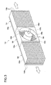
FIG. 3 is a perspective illustration of aheatsink 114 and afan 156 of an automotive lamp according to a second embodiment of the present invention. Though the structure of the automotive lamp according to the second embodiment is basically the same as that of theautomatic lamp 10 shown inFIG. 1 , the structure differs in theheatsink 114 and thefan 156. Note that the structural components identical or equivalent to those in the first embodiment are denoted with the same reference numerals as those therein, and the repeated description thereof will be omitted as appropriate. - In the second embodiment, the
heatsink 114 is comprised of afirst sub-heatsink 150, asecond sub-heatsink 152, and athird sub-heatsink 154. In theheatsink 114, thesecond sub-heatsink 152 is located in the middle, with thefirst sub-heatsink 150 on the left and thethird sub-heatsink 154 on the right facing frontward from theautomotive lamp 10. The first lamp unit is mounted to thefirst sub-heatsink 150, the second lamp unit to thesecond sub-heatsink 152, and the third lamp unit to the third sub-heatsink 154 (first to third lamp units being not shown inFIG. 3 ). - The
first sub-heatsink 150 is comprised of afirst base part 150a and a plurality offirst plate fins 150b mounted upright on thefirst base part 150a in parallel with each other at predetermined intervals. Formed between the plurality offirst plate fins 150b are a plurality of ventilation passages in parallel with each other. Also, thethird sub-heatsink 154 is comprised of athird base part 154a and a plurality ofthird plate fins 154b mounted upright on thethird base part 54a in parallel with each other at predetermined intervals. Formed between the plurality ofthird plate fins 154b are a plurality of ventilation passages in parallel with each other. On the other hand, thesecond sub-heatsink 152 is comprised of asecond base part 152a and a plurality ofpin fins 152b disposed upright on thesecond base part 152a in parallel with each other at predetermined intervals. - The
first base part 150a, thesecond base part 152a and thethird base part 154a are formed by a single plate member. In this manner, forming the first tothird base parts 150a to 154a by a single plate member allows handling of the first tothird sub-heatsinks 150 to 154 as a single assembly. As a result, the handling can be easy and the assembly can be installed on thelamp body 48 with great ease. Alternatively, however, the first tothird base parts 150a to 154a may be formed as separate bodies, in which case the manufacture of the first tothird sub-heatsinks 150 to 154 can be made easier. - In the second embodiment, the
first plate fins 150b of thefirst sub-heatsink 150 are so formed as to extend in the left-right (horizontal) direction. Also, thethird plate fins 154b of thethird sub-heatsink 154 are so formed as to extend in the left-right (horizontal) direction. Thepin fins 152b of thesecond sub-heatsink 152 are so formed as to have a predetermined arrangement pattern. - The
first plate fins 150b and thethird plate fins 154b are so formed as to be approximately the same in height from the base part. On the other hand, thepin fins 152b are so formed that the height from the base part thereof is about half that of thefirst plate fins 150b and thethird plate fins 154b. Accordingly, there results a space, between thefirst plate fins 150b and thethird plate fins 154b, recessed as much as thepin fins 152b are lower in height than thefirst plate fins 150b and thethird plate fins 154b. - A
fan 156 is installed on thepin fins 152b in such a manner that it fits into the above-mentioned recessed space. Thefan 156 is a fan, which combines a centrifugal fan and an axial flow fan, structured such that the air drawn in from one axial direction can be discharged in a plurality of directions perpendicular to the axial direction and at the same time can be discharged in the other axial direction. Thefan 156 has anair inlet 156a in the rear in the axial direction for drawing air in, a front-side air outlet 156b for discharging air in the front in the axial direction of thefan 156, an air outlet 156c in the left side thereof for discharging air leftward perpendicular to the axial direction thereof, and anair outlet 156d in the right side thereof for discharging air rightward perpendicular to the axial direction thereof. As power is supplied to a motor (not shown) of thefan 156 and fan blades begin rotating (here the fan blades are not shown inFIG. 3 for the purpose of making thepin fins 152b more visible), air is drawn in through the axiallyrear air inlet 156a and then discharged frontward, leftward and rightward through the front-side air outlet 156b, the left-side air outlet 156c and the right-side air outlet 156d, respectively, - As air is discharged frontward through the front-
side air outlet 156b, thesecond sub-heatsink 152 is subjected to a forced air cooling. The left-side air outlet 156c and the right-side air outlet 156d of thefan 156 are so formed that the height thereof is about half that of thefirst plate fins 150b and thethird plate fins 154b. Hence, when thefan 156 is installed on thesecond sub-heatsink 152, the entrances of the ventilation passages of thefirst sub-heatsink 150 face the left-side air outlet 156c and the entrances of the ventilation passages of the third sub-heatsink 154 face the right-side air outlet 156d. As a result, most of the air discharged leftward from the left-side air outlet 56c flows into the ventilation passages between thefirst plate fins 150b, so that thefirst sub-heatsink 150 is subjected to a forced air cooling. Likewise, most of the air discharged rightward from the right-side air outlet 156d flows into the ventilation passages between thethird plate fins 154b, so that thethird sub-heatsink 154 is subjected to a forced air cooling. - In this manner, in the second embodiment the air drawn in through the axially
rear air inlet 156a is discharged in three directions, namely, frontward, leftward and rightward. Hence, the air can be sent to as many regions of theheatsink 114 as possible. As a result, the heat produced by each lamp unit can be radiated efficiently. - Next, a heat radiation mechanism in the automotive lamp according to the second embodiment will be described. In
FIG. 3 , white arrows indicate the flows of air. In the automotive lamp as shown inFIG. 3 , as theLED 20 of eachlamp unit 30 emits light, the heat resulting from the emission of light is conducted to the mountingmember 26 through the thermally conductive insulatingsubstrate 24 with which theLED 20 is in contact. The heat conducted to the mountingmember 26 of eachlamp unit 30 is conducted to the base part of each sub-heatsink with which the rear end of each mountingmember 26 is in contact. The heat conducted to thefirst base part 150a and thethird base part 154a is conducted to thefirst plate fins 150b and thethird plate fins 154b before it is radiated into the surrounding air. Also, the heat conducted to thesecond base part 152a is conducted to thepin fins 152b before it is radiated into the surrounding air. - As the fan blades are rotated with power supplied to the motor of the
fan 156 and, air is drawn in through the axiallyrear air inlet 156a and then discharged frontward, leftward and rightward through the front-side air outlet 156b, the left-side air outlet 156c and the right-side air outlet 156d, respectively. - With the air discharged forward from the front-
side air outlet 156b, thepin fins 152b are exposed to the air. The air whose temperature is raised by the heat radiated from thepin fins 152b is diffused in all directions through spaces between the pin fins 162. After thesecond sub-heatsink 152 is subjected to a forced air cooling, the diffused air flows into thefirst sub-heatsink 150 and thethird sub-heatsirik 154, so that thefirst sub-heatsink 150 and thethird sub-heatsink 154 are subjected to a forced air cooling. - The air discharged from the left-side air outlet 156c of the
fan 156 flows through the entrances facing the left-side air outlet 156c into the ventilation passages of thefirst sub-heatsink 150. As a result, the air whose temperature is raised by the heat radiated from thefirst plate fins 150b is discharged from the exits of the ventilation passages as shown inFIG. 3 . Similarly, the air discharged from the right-side air outlet 156d of thefan 156 flows through the entrances facing the right-side air outlet 156d into the ventilation passages of thethird sub-heatsink 154. As a result, the air whose temperature is raised by the heat radiated from thethird plate fins 154b is discharged from the exits of the ventilation passages as shown inFIG. 3 . - By the mechanism as described above, the sub-heatsinks of the
heatsink 114 are subjected to a forced air cooling, and the heat produced by thelamp units 30 connected to the respective sub-heatsinks is radiated. In the second embodiment, the air from thefan 156 is discharged in three directions, namely, frontward, leftward and rightward. Also, the plate fins are formed such that the entrances of the ventilation passages of thefirst sub-heatsink 150 and the third sub-heatsink 154 face the left-side air outlet 156c and the right-side air outlet 156d, respectively. Further, thepin fins 152b are formed in the axially front direction of thefan 156. This configuration increases the number of parts of theheatsink 114 that are exposed to the drafts of air sent. As a result, the forced air cooling of theheatsink 114 is better facilitated, thus radiating the heat produced by theLED 20 more efficiently. - Also, in the second embodiment, the fins for the
second sub-heatsink 152 disposed frontward of thefan 156 is pin-fin shaped. For example, if the fins for thesecond sub-heatsink 152 are plate fins, the air discharged forward in the axial direction will flow in the left and right directions through the ventilation passages between the plate fins and therefore the wind velocity will differ between each of the ventilation passages of thefirst sub-heatsink 150 and each of the ventilation passages of thethird sub-heatsink 154. By employing the pin fins as the fins for thesecond sub-heatsink 152 as with this second embodiment, the directional characteristics in the surface direction of air discharged forward in the axial direction can be eliminated. Thus the difference in wind velocity between each of the ventilation passages of thefirst sub-heatsink 150 and each of the ventilation passages of thethird sub-heatsink 154 will be less likely to be caused and the forced air cooling can be done uniformly. - Moreover, in the second embodiment, a recessed space is provided by the
pin fins 152b whose height from the base part is lower than the plate fins of the sub-heatsinks on both sides, and thefan 156 is fitted into the recessed space. This configuration realizes a compact heat radiation structure theheatsink 114 and thefan 156 in combination. And this heat radiation structure can be applied for use in more automotive lamps. - The present invention has been described by referring to each of the above-described embodiments and such description is for illustrative purposes only. It is understood by those skilled in the art that various modifications to constituting elements and processes could be developed and that such modifications are also within the scope of the present invention.
- In the above-described embodiments, LEDs are used as the light source. However, this should not be considered as limiting and, for example, semiconductor light emitting devices such as semiconductor laser may be used.
- In the above-described embodiments, a projector-type lamp unit is used but this should not be considered as limiting and, for example, a parabola-type or direct-emitting-type lamp unit may be used.
- In the above-described embodiments, two air outlets are provided for discharging the air in the axial and vertical directions but this should not be considered as limiting. A plurality of air outlets in more different directions than two may be provided for the fan. In such a case, a plate fin is formed so that at least one entrance of the ventilation passages of the heatsink faces each air outlet.
- In the
heatsink 14 shown inFIG. 2 , a cover or covers used to prevent the air sent from thecentrifugal fan 56 from being leaked along the ventilation passages may be provided at upper ends of thefirst plate fins 50b and thethird plate fins 54b (at the ends opposite to thefirst base part 50a side and thethird base part 54a side). In this case, the wind velocity at regions away from the left-side air outlet 56c and the right-side air outlet 56d does not drop, so that the heat can be radiated efficiently. A similar cover or covers as described above may be applied to theheatsink 114 ofFIG. 3 . - The invention is not restricted to the features of the described embodiments.
Claims (11)
- An automotive lamp (10) comprising:a semiconductor light emitting device (10) as a light source;a heatsink (14, 114) configured to radiate heat produced by the semiconductor light emitting device (20), the heatsink including a plurality of plate fins (50b, 54b, 150b, 154b) installed upright on a base part (50a, 54a, 150a, 154a) and a plurality of ventilation passages formed between the plate fins (50b, 54b, 150b, 154b);a centrifugal fan (56, 156) configured to perform a forced air cooling of the plate fins (50b, 54b, 150b, 154b) by sending air through the ventilation passages of the heatsink (14, 114), the centrifugal fan having air inlets (56a, 56b, 156a) open in an axial direction thereof for drawing air in and a plurality of air outlets (56c, 56d, 156c, 156d) for discharging air in a plurality of directions perpendicular to the axial direction thereof; anda lamp housing which houses the semiconductor light emitting device (20), heatsink (14, 114), and centrifugal fan (56, 156),wherein the plate fins (50b, 54b, 150b, 154b) of the heatsink (14, 114) are formed such that an entrance of at least one of the plurality of ventilation passages faces each of the air outlets (56c, 56d, 156c, 156d) of the centrifugal fan (56, 156).
- An automotive lamp according to claim 1, wherein each ventilation passage whose entrance faces each of the air outlets (56c, 56d, 156c, 156d) of the centrifugal fan (56, 156) extends in a direction parallel to an air discharge direction of each of the air outlets (56c, 56d, 156c, 156d).
- An automotive lamp according to claim 1 or claim 2,
wherein the heatsink (14) further includes a plurality of fins (52b) in the axial direction of the centrifugal fan (56), and the plurality of fins (52b) are subjected to a forced air cooling by an intake of air caused by the centrifugal fan (56). - An automotive lamp according to claim 3, wherein the fins (52b) which are subjected to a forced air cooling by an intake of air caused by the centrifugal fan (56) are plate fins, and
the plate fins (52b) extend in a direction perpendicular to a direction in which the plate fins (50b, 54b), which are subjected to a forced air cooling by a discharge of air caused by the centrifugal fan (56), extend. - An automotive lamp according to claim 4, wherein the plate fins (52b) which are subjected to a forced air cooling by an intake of air caused by the centrifugal fan (56) are formed in a manner such that the height thereof is lower than that of the plate fins (50b, 54b) which are subjected to a forced air cooling by a discharge of air caused by the centrifugal fan (56).
- An automotive lamp according to claim 5, wherein the centrifugal fan (56) is installed on the plate fins (52b) which are subjected to a forced cooling air by an intake of air caused by the centrifugal fan (56).
- An automotive lamp according to claim 1 or claim 2,
wherein the centrifugal fan (156) is structured such that air drawn in from one axial direction is dischargeable in a plurality of directions perpendicular to the axial direction and is dischargeable in the other axial direction, and
wherein regions of the heatsink (114) in the other axial direction of the centrifugal fan (156) are subject to a forced air cooling by a discharge of air caused by the centrifugal fan (56) in the other axial direction. - An automotive lamp according to claim 7, wherein a plurality of pin fins (152b) are provided on the regions of the heatsink (114) in the other axial direction of the centrifugal fan (156).
- An automotive lamp according to claim 8, wherein the pin fins (152b) are formed in a manner such that the height thereof is lower than that of the plate fins (150b, 154b) which are subjected to a forced air cooling by a discharge of air in a direction perpendicular to the axial direction of the centrifugal fan (156).
- An automotive lamp according to claim 9, wherein the centrifugal fan (156) is installed on the pin fins (152b).
- An automotive lamp according to any one of claim 1 to claim 10, wherein a cover used to prevent air sent from the centrifugal fan (56, 156) from being leaked along the ventilation passages is provided at upper ends of the plate fins (50b, 54b, 150b, 154b).
Applications Claiming Priority (1)
| Application Number | Priority Date | Filing Date | Title |
|---|---|---|---|
| JP2008163220A JP5160973B2 (en) | 2008-06-23 | 2008-06-23 | Vehicle lighting |
Publications (1)
| Publication Number | Publication Date |
|---|---|
| EP2138759A1 true EP2138759A1 (en) | 2009-12-30 |
Family
ID=40935005
Family Applications (1)
| Application Number | Title | Priority Date | Filing Date |
|---|---|---|---|
| EP20090163408 Withdrawn EP2138759A1 (en) | 2008-06-23 | 2009-06-22 | Automotive lamp |
Country Status (5)
| Country | Link |
|---|---|
| US (1) | US8118462B2 (en) |
| EP (1) | EP2138759A1 (en) |
| JP (1) | JP5160973B2 (en) |
| KR (1) | KR101116089B1 (en) |
| CN (1) | CN101614355A (en) |
Cited By (6)
| Publication number | Priority date | Publication date | Assignee | Title |
|---|---|---|---|---|
| WO2014170484A1 (en) * | 2013-04-19 | 2014-10-23 | Valeo Vision | Cooling member and motor vehicle lighting or signalling device comprising such a member |
| EP3043107A1 (en) | 2015-01-09 | 2016-07-13 | Valeo Vision | Optical module for motor vehicle headlight |
| EP3173684A1 (en) * | 2015-11-27 | 2017-05-31 | Valeo Vision | Lighting module of a motor vehicle headlight and associated headlight |
| KR20170103796A (en) | 2015-01-09 | 2017-09-13 | 발레오 비젼 | Optical module for vehicle headlight |
| EP3561375A1 (en) * | 2018-04-27 | 2019-10-30 | Valeo Iluminacion, | Cooling device for an automotive luminous device |
| WO2024022215A1 (en) * | 2022-07-25 | 2024-02-01 | 北京有竹居网络技术有限公司 | Data center cooling system, computer room, and method |
Families Citing this family (34)
| Publication number | Priority date | Publication date | Assignee | Title |
|---|---|---|---|---|
| JP5248183B2 (en) * | 2008-04-22 | 2013-07-31 | 株式会社小糸製作所 | Vehicle lighting |
| TWI417635B (en) * | 2009-12-30 | 2013-12-01 | Qisda Corp | Electronic apparatus and projector |
| TWM389053U (en) * | 2010-03-11 | 2010-09-21 | Asia Vital Components Co Ltd | Structure of moisture-proof prevent fog LED vehicle lamp |
| JP5149324B2 (en) | 2010-03-31 | 2013-02-20 | 株式会社日本自動車部品総合研究所 | Vehicle headlamp |
| US20110310631A1 (en) * | 2010-06-22 | 2011-12-22 | Bayer Materialscience Llc | Led headlamp cooling system |
| KR101217222B1 (en) | 2010-10-04 | 2012-12-31 | 주식회사 아모텍 | Head lamp for vehicle |
| CN102095148A (en) * | 2010-12-14 | 2011-06-15 | 孟强 | LED (light emitting diode) headlamp of electric automobile |
| TWI414722B (en) * | 2011-03-17 | 2013-11-11 | Sunonwealth Electr Mach Ind Co | Lamp |
| US9839206B2 (en) | 2011-06-22 | 2017-12-12 | Ecotech Marine, Llc | Lighting unit and method of controlling |
| WO2013071972A1 (en) * | 2011-11-17 | 2013-05-23 | Osram Gmbh | Led light source module |
| JP5810900B2 (en) * | 2011-12-26 | 2015-11-11 | 市光工業株式会社 | Vehicle lighting |
| JP6014253B2 (en) * | 2012-07-25 | 2016-10-25 | シェンツェン イーク エレクトロオプティカル テクノロジー カンパニー リミテッド | LED headlamps for automobiles |
| KR101931492B1 (en) | 2012-08-30 | 2018-12-21 | 삼성전자주식회사 | Light source assembly |
| NL1040116B3 (en) * | 2013-03-22 | 2026-04-23 | Nges Holding B V | Illumination device for stimulating plant growth. |
| JP6235786B2 (en) | 2013-03-26 | 2017-11-22 | 株式会社小糸製作所 | Cooling unit and lighting device |
| KR101592649B1 (en) * | 2013-12-24 | 2016-02-12 | 현대자동차주식회사 | Laser optical system for head lamp |
| CN104329648A (en) * | 2014-03-10 | 2015-02-04 | 冯西芳 | Heat management device and method of automotive high-power LED lighting lamp |
| CN103995422A (en) * | 2014-05-22 | 2014-08-20 | 无锡启晖光电科技有限公司 | Cooling mechanism of projector lamp bulb |
| CN104197217A (en) * | 2014-08-28 | 2014-12-10 | 赵春荣 | Active cooling type LED energy-saving lamp |
| FR3037125B1 (en) * | 2015-06-08 | 2019-10-11 | Valeo Vision | THERMAL DISSIPATOR FOR LIGHT EMITTING MODULE, LIGHT EMITTING MODULE AND LUMINOUS DEVICE THEREFOR |
| CN105588056A (en) * | 2016-01-28 | 2016-05-18 | 太仓市高泰机械有限公司 | Car lamp heat radiator |
| FR3048487B1 (en) * | 2016-03-02 | 2019-05-24 | Valeo Vision | LIGHTING DEVICE FOR A MOTOR VEHICLE COMPRISING COOLING LIGHT MODULES USING A GENERATOR OF AN AIR FLOW |
| SG10201609616TA (en) | 2016-09-06 | 2018-04-27 | Apple Inc | Electronic device with cooling fan |
| JP2017159657A (en) * | 2017-04-07 | 2017-09-14 | Hoya Candeo Optronics株式会社 | Light irradiation device |
| US10285303B2 (en) * | 2017-07-14 | 2019-05-07 | Apple Inc. | Electronic device with integrated passive and active cooling |
| US10415787B2 (en) | 2018-01-11 | 2019-09-17 | Osram Sylvania Inc. | Vehicle LED lamp having recirculating air channels |
| CN110043861B (en) * | 2019-04-02 | 2023-11-14 | 东莞市莱硕光电科技有限公司 | LED automobile lamp |
| US11746986B2 (en) | 2019-05-15 | 2023-09-05 | Magna Exteriors Inc. | Vehicle lighting with thermal control |
| CN110793006A (en) * | 2019-10-25 | 2020-02-14 | 深圳市冠科科技有限公司 | Heat radiator and high-power electric light source |
| IT201900022209A1 (en) | 2019-11-26 | 2021-05-26 | Osram Gmbh | Lamp and corresponding procedure |
| EP4096376B1 (en) * | 2021-05-24 | 2025-09-24 | Aptiv Technologies AG | Cooling device and heatsink assembly incorporating the same |
| FR3130942B1 (en) * | 2021-12-17 | 2024-03-29 | Valeo Vision | Cooling system for vehicle lighting module |
| WO2026047413A1 (en) | 2024-08-29 | 2026-03-05 | Osram Gmbh | Retrofit automotive led lamp |
| WO2026047414A1 (en) | 2024-08-29 | 2026-03-05 | Osram Gmbh | Driver circuit for lamps, and corresponding lamp and method |
Citations (6)
| Publication number | Priority date | Publication date | Assignee | Title |
|---|---|---|---|---|
| JP2005340065A (en) * | 2004-05-28 | 2005-12-08 | Harison Toshiba Lighting Corp | Light emitting diode backlight device |
| EP1643188A1 (en) * | 2004-09-29 | 2006-04-05 | Osram Opto Semiconductors GmbH | LED arrangement with cooling means and vehicle headlight |
| JP2006286395A (en) | 2005-03-31 | 2006-10-19 | Ichikoh Ind Ltd | Vehicle lighting |
| DE102005060736A1 (en) * | 2005-12-16 | 2007-07-05 | Schefenacker Vision Systems Germany Gmbh | Headlamp has housing, light source, and conveyer device that carries air from heat source along headlamp glass, where heat sink has condensate drain and connects interior of headlamp with surrounding area |
| US20070297183A1 (en) * | 2006-06-21 | 2007-12-27 | Coushaine Charles M | Heat sink |
| DE102006037481A1 (en) * | 2006-08-10 | 2008-02-21 | Dr.Ing.H.C. F. Porsche Ag | Headlight module, particularly additional upper beam headlight module, for vehicle, has reflectors, which reflect light |
Family Cites Families (8)
| Publication number | Priority date | Publication date | Assignee | Title |
|---|---|---|---|---|
| CN2479645Y (en) | 2001-03-29 | 2002-02-27 | 台达电子工业股份有限公司 | Embedded centrifugal cooling unit |
| JP4270153B2 (en) * | 2005-04-05 | 2009-05-27 | 市光工業株式会社 | Vehicle lighting |
| JP4600767B2 (en) * | 2005-11-02 | 2010-12-15 | スタンレー電気株式会社 | LED lamp |
| TWI290777B (en) * | 2006-02-27 | 2007-12-01 | Guei-Fang Chen | Lighting device with light emitting diode |
| US7866852B2 (en) * | 2007-08-29 | 2011-01-11 | Texas Instruments Incorporated | Heat sinks for cooling LEDs in projectors |
| JP5248183B2 (en) * | 2008-04-22 | 2013-07-31 | 株式会社小糸製作所 | Vehicle lighting |
| JP5342553B2 (en) * | 2008-06-06 | 2013-11-13 | 株式会社小糸製作所 | Vehicle lighting |
| CN101603673A (en) * | 2008-06-13 | 2009-12-16 | 富准精密工业(深圳)有限公司 | Light emitting diode illuminating apparatus |
-
2008
- 2008-06-23 JP JP2008163220A patent/JP5160973B2/en not_active Expired - Fee Related
-
2009
- 2009-06-19 KR KR1020090054876A patent/KR101116089B1/en not_active Expired - Fee Related
- 2009-06-22 EP EP20090163408 patent/EP2138759A1/en not_active Withdrawn
- 2009-06-23 US US12/490,058 patent/US8118462B2/en not_active Expired - Fee Related
- 2009-06-23 CN CN200910150314A patent/CN101614355A/en active Pending
Patent Citations (6)
| Publication number | Priority date | Publication date | Assignee | Title |
|---|---|---|---|---|
| JP2005340065A (en) * | 2004-05-28 | 2005-12-08 | Harison Toshiba Lighting Corp | Light emitting diode backlight device |
| EP1643188A1 (en) * | 2004-09-29 | 2006-04-05 | Osram Opto Semiconductors GmbH | LED arrangement with cooling means and vehicle headlight |
| JP2006286395A (en) | 2005-03-31 | 2006-10-19 | Ichikoh Ind Ltd | Vehicle lighting |
| DE102005060736A1 (en) * | 2005-12-16 | 2007-07-05 | Schefenacker Vision Systems Germany Gmbh | Headlamp has housing, light source, and conveyer device that carries air from heat source along headlamp glass, where heat sink has condensate drain and connects interior of headlamp with surrounding area |
| US20070297183A1 (en) * | 2006-06-21 | 2007-12-27 | Coushaine Charles M | Heat sink |
| DE102006037481A1 (en) * | 2006-08-10 | 2008-02-21 | Dr.Ing.H.C. F. Porsche Ag | Headlight module, particularly additional upper beam headlight module, for vehicle, has reflectors, which reflect light |
Cited By (14)
| Publication number | Priority date | Publication date | Assignee | Title |
|---|---|---|---|---|
| FR3004787A1 (en) * | 2013-04-19 | 2014-10-24 | Valeo Vision | COOLING DEVICE AND LIGHTING OR SIGNALING DEVICE FOR A MOTOR VEHICLE COMPRISING SUCH AN ORGAN |
| WO2014170484A1 (en) * | 2013-04-19 | 2014-10-23 | Valeo Vision | Cooling member and motor vehicle lighting or signalling device comprising such a member |
| US9857047B2 (en) | 2013-04-19 | 2018-01-02 | Valeo Vision | Cooling member and motor vehicle lighting or signaling device comprising such a member |
| US10072810B2 (en) | 2015-01-09 | 2018-09-11 | Valeo Vision | Optical module for a vehicle headlamp |
| EP3043107A1 (en) | 2015-01-09 | 2016-07-13 | Valeo Vision | Optical module for motor vehicle headlight |
| US10859233B2 (en) | 2015-01-09 | 2020-12-08 | Valeo Vision | Optical module for a vehicle headlamp |
| KR20170103796A (en) | 2015-01-09 | 2017-09-13 | 발레오 비젼 | Optical module for vehicle headlight |
| EP3173684A1 (en) * | 2015-11-27 | 2017-05-31 | Valeo Vision | Lighting module of a motor vehicle headlight and associated headlight |
| US10309636B2 (en) | 2015-11-27 | 2019-06-04 | Valeo Vision | Motor vehicle headlight lighting module with wavelength converter and separate air ducts for cooling |
| FR3044393A1 (en) * | 2015-11-27 | 2017-06-02 | Valeo Vision | MOTOR VEHICLE PROJECTOR LIGHTING MODULE AND PROJECTOR |
| EP3561375A1 (en) * | 2018-04-27 | 2019-10-30 | Valeo Iluminacion, | Cooling device for an automotive luminous device |
| CN110410752A (en) * | 2018-04-27 | 2019-11-05 | 法雷奥照明公司 | Cooling device for light emitting device for vehicle |
| US10914449B2 (en) | 2018-04-27 | 2021-02-09 | Valeo Iluminacion | Cooling device for an automotive luminous device |
| WO2024022215A1 (en) * | 2022-07-25 | 2024-02-01 | 北京有竹居网络技术有限公司 | Data center cooling system, computer room, and method |
Also Published As
| Publication number | Publication date |
|---|---|
| US20090316425A1 (en) | 2009-12-24 |
| JP5160973B2 (en) | 2013-03-13 |
| KR20090133084A (en) | 2009-12-31 |
| CN101614355A (en) | 2009-12-30 |
| US8118462B2 (en) | 2012-02-21 |
| KR101116089B1 (en) | 2012-02-14 |
| JP2010003621A (en) | 2010-01-07 |
Similar Documents
| Publication | Publication Date | Title |
|---|---|---|
| US8118462B2 (en) | Automotive lamp | |
| JP5342553B2 (en) | Vehicle lighting | |
| JP5248183B2 (en) | Vehicle lighting | |
| JP6061638B2 (en) | Vehicle lighting | |
| JP5405043B2 (en) | Vehicle lighting | |
| CN105180049B (en) | Optical module for a motor vehicle headlight | |
| JP2011187264A (en) | Lighting system | |
| JP2008059965A (en) | Vehicle headlamp, lighting device and heat dissipation member thereof | |
| EP3475608B1 (en) | Lighting assembly for emitting high intensity light, a light source, a lamp and a luminaire | |
| CN209909794U (en) | Cooling unit and vehicle lamp | |
| US10851964B2 (en) | Lighting fixture for vehicle | |
| KR20200065859A (en) | Lighting apparatus for mounting drone | |
| EP3578873A1 (en) | Lighting fixture for vehicle | |
| JP2009295513A (en) | Vehicular lighting fixture | |
| JP5847574B2 (en) | High-speed illuminator | |
| JP2013016681A (en) | Heat radiation member and heat radiation mechanism | |
| CN103339437B (en) | Lighting device | |
| JP5909699B2 (en) | Vehicle headlamp | |
| JP2026005846A (en) | lighting fixtures | |
| CN121048115A (en) | Vehicle lights, especially motor vehicle headlights | |
| JP2012226960A (en) | Lighting fixture |
Legal Events
| Date | Code | Title | Description |
|---|---|---|---|
| PUAI | Public reference made under article 153(3) epc to a published international application that has entered the european phase |
Free format text: ORIGINAL CODE: 0009012 |
|
| 17P | Request for examination filed |
Effective date: 20090622 |
|
| AK | Designated contracting states |
Kind code of ref document: A1 Designated state(s): AT BE BG CH CY CZ DE DK EE ES FI FR GB GR HR HU IE IS IT LI LT LU LV MC MK MT NL NO PL PT RO SE SI SK TR |
|
| 17Q | First examination report despatched |
Effective date: 20130730 |
|
| GRAP | Despatch of communication of intention to grant a patent |
Free format text: ORIGINAL CODE: EPIDOSNIGR1 |
|
| RIC1 | Information provided on ipc code assigned before grant |
Ipc: F21V 29/02 20060101ALI20141104BHEP Ipc: F21S 8/10 20060101ALI20141104BHEP Ipc: F21Y 101/02 20060101AFI20141104BHEP |
|
| INTG | Intention to grant announced |
Effective date: 20141208 |
|
| GRAP | Despatch of communication of intention to grant a patent |
Free format text: ORIGINAL CODE: EPIDOSNIGR1 |
|
| RIC1 | Information provided on ipc code assigned before grant |
Ipc: F21V 29/00 20150101AFI20150319BHEP Ipc: F21Y 101/02 20060101ALI20150319BHEP Ipc: F21S 8/10 20060101ALI20150319BHEP |
|
| INTG | Intention to grant announced |
Effective date: 20150331 |
|
| STAA | Information on the status of an ep patent application or granted ep patent |
Free format text: STATUS: THE APPLICATION IS DEEMED TO BE WITHDRAWN |
|
| 18D | Application deemed to be withdrawn |
Effective date: 20150811 |