EP2139721B1 - Verkaufswagen mit vorrichtung zur bewegung und/oder ausladung von tresen und entsprechendes handhabungsvorfahren - Google Patents
Verkaufswagen mit vorrichtung zur bewegung und/oder ausladung von tresen und entsprechendes handhabungsvorfahren Download PDFInfo
- Publication number
- EP2139721B1 EP2139721B1 EP08709870A EP08709870A EP2139721B1 EP 2139721 B1 EP2139721 B1 EP 2139721B1 EP 08709870 A EP08709870 A EP 08709870A EP 08709870 A EP08709870 A EP 08709870A EP 2139721 B1 EP2139721 B1 EP 2139721B1
- Authority
- EP
- European Patent Office
- Prior art keywords
- counter
- vending van
- van according
- vending
- supporting elements
- Prior art date
- Legal status (The legal status is an assumption and is not a legal conclusion. Google has not performed a legal analysis and makes no representation as to the accuracy of the status listed.)
- Active
Links
- 238000000034 method Methods 0.000 title abstract description 10
- 230000005484 gravity Effects 0.000 claims description 7
- 230000008878 coupling Effects 0.000 claims description 5
- 238000010168 coupling process Methods 0.000 claims description 5
- 238000005859 coupling reaction Methods 0.000 claims description 5
- 230000000694 effects Effects 0.000 claims description 4
- 230000000284 resting effect Effects 0.000 description 11
- 230000009471 action Effects 0.000 description 9
- 230000008901 benefit Effects 0.000 description 7
- 238000006073 displacement reaction Methods 0.000 description 5
- 238000010276 construction Methods 0.000 description 4
- 230000010355 oscillation Effects 0.000 description 3
- 230000009467 reduction Effects 0.000 description 2
- 230000002787 reinforcement Effects 0.000 description 2
- 230000001419 dependent effect Effects 0.000 description 1
- 238000010586 diagram Methods 0.000 description 1
- 230000005611 electricity Effects 0.000 description 1
- 239000012530 fluid Substances 0.000 description 1
- 231100001261 hazardous Toxicity 0.000 description 1
- 238000012423 maintenance Methods 0.000 description 1
- 239000000463 material Substances 0.000 description 1
- 230000007246 mechanism Effects 0.000 description 1
- 230000004048 modification Effects 0.000 description 1
- 238000012986 modification Methods 0.000 description 1
- 230000003287 optical effect Effects 0.000 description 1
- 238000004321 preservation Methods 0.000 description 1
- 238000002604 ultrasonography Methods 0.000 description 1
- 238000005303 weighing Methods 0.000 description 1
Images


Classifications
-
- B—PERFORMING OPERATIONS; TRANSPORTING
- B60—VEHICLES IN GENERAL
- B60P—VEHICLES ADAPTED FOR LOAD TRANSPORTATION OR TO TRANSPORT, TO CARRY, OR TO COMPRISE SPECIAL LOADS OR OBJECTS
- B60P3/00—Vehicles adapted to transport, to carry or to comprise special loads or objects
- B60P3/025—Vehicles adapted to transport, to carry or to comprise special loads or objects the object being a shop, cafeteria or display the object being a theatre or stage
- B60P3/0257—Vehicles adapted to transport, to carry or to comprise special loads or objects the object being a shop, cafeteria or display the object being a theatre or stage the object being a vending stall, restaurant or food kiosk
-
- B—PERFORMING OPERATIONS; TRANSPORTING
- B60—VEHICLES IN GENERAL
- B60P—VEHICLES ADAPTED FOR LOAD TRANSPORTATION OR TO TRANSPORT, TO CARRY, OR TO COMPRISE SPECIAL LOADS OR OBJECTS
- B60P1/00—Vehicles predominantly for transporting loads and modified to facilitate loading, consolidating the load, or unloading
- B60P1/44—Vehicles predominantly for transporting loads and modified to facilitate loading, consolidating the load, or unloading having a loading platform thereon raising the load to the level of the load-transporting element
Definitions
- the invention relates to the sector of vehicles used for itinerant sales, also called vending vans.
- the present invention refers to vehicles used for itinerant sales that are equipped with a counter of the so-called unloadable type.
- the present invention relates to a vending van complete with a device for moving a counter and/or unloading it onto the ground, and a related handling procedure.
- These vehicles usually have a counter for the sale of the products, as well as display cases on the walls and/or specific machinery such as refrigerators, ovens, deep fryers, slicers, etc.
- the counter may be fixed and incorporated in the vending van or it may be movable on the floor of the vending van and/or unloadable, i.e. suitable for being displaced outside the loading compartment of the vehicle used as a vending van and for being placed on the ground after the van has been parked.
- these cranes lift the counter off the vehicle floor and move it horizontally in order to lower it outside the vehicle and rest it on the ground.
- the counter is deposited on the ground as close as possible to the side of the vending van and it is likewise reloaded from the same position.
- the user must then take action manually to move it further away so as to create the corridor needed between the side of the vehicle and the counter, where he/she can work while selling the goods.
- a first drawback of these solutions lies in that the loading compartment of the vehicle, and the walls of the loading compartment in particular, must be suitably reinforced in order to be able to sustain the weight both of the crane and of the load that it lifts, and this has a considerable negative influence on the cost of the vending van. It is worth adding here that the load can be as much as 2 metric tons.
- Another drawback lies in that, being positioned in the upper part of the loading compartment of the vehicle used as a vending van, the crane raises the vehicle's centre of gravity, with a negative effect on its stability, making the vending van easily liable to unwanted oscillations and unbalancing.
- a further drawback lies in that they are structurally rather complex and noisy when in operation.
- a further example of a vending van according to the prior art is disclosed in document FR-A-2 265 323 .
- the object of the present invention is to overcome the aforementioned drawbacks.
- a first object of the invention is to construct a vending van with a device for moving and/or unloading the counters used for sales that can be installed in vending vans and a handling procedure that enables the previously-mentioned drawbacks to be overcome.
- Another object of the present invention is to construct a vending van with a fully automatic moving and/or unloading device that is particularly straightforward and efficient, and with a lower power consumption than the known devices and/or systems when in operation, for the same load.
- Another object of the present invention is to construct a handling device that, installed in a vending van for which it is designed, has a negligible influence on the position of the centre of gravity of the van.
- Another object of the present invention is to construct a device and a system capable of operating without generating any hazardous oscillations or unbalance in the vending van in which they are installed.
- a further object of the present invention is to construct a vending van with a handling device and to implement a procedure that enables a counter to be moved from at least one resting position inside the vending van to at least one working position (preferably on the ground) for the sale of products, in such a way as to ensure easy access for the salespeople.
- Another object of the present invention is to construct a vending van with a handling device that is easy to service and highly reliable.
- Another object of the present invention is to construct a vending van with a handling device that is economical and easy to use, as well as being easy to construct, assemble and install.
- Another object of the present invention is to construct a vending van with a counter moving and/or unloading device that also enables a quick and easy levelling of the counter in the working position to make it ready for use and arrange it in the most suitable manner for displaying and selling the goods.
- the proposed solution advantageously enables the construction of a vending van with a counter moving and/or unloading device that enables the space inside the vehicle to be used at will and managed efficiently, exploiting its maximum capacity when the counter is moved outside the vending van.
- This also enables an optimal management of the furniture behind the counter, particularly as concerns the dimensions of the shelving, refrigerators, ovens and any other machinery and equipment.
- the proposed solution also advantageously enables the counter to be carried outside the vending van and lowered onto the ground at a greater distance from the side of the van than is normally possible using the known devices and/or systems, so that the salespeople can move with ease between the vending van and the counter.
- Another advantage of the proposed solution is that it enables the construction of a vending van with a handling device that is more lightweight and quieter than the known devices and/or systems.
- Another advantage of the proposed solution is that it enables the construction of a device and a system that do not substantially interfere with the load-bearing capacity of the vending van in which they are installed.
- Another advantage of the proposed device is that it has minimal overall dimensions and the stability and balance of the vehicle are unaffected when it is used.
- Another advantage of the proposed device and system is that they enable the counter to be raised and/or lowered on to the ground and to be brought to the required height while its plane remains horizontal, so that the consumers can be served in optimal conditions.
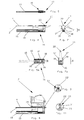
- FIG. 500 An embodiment of a vending van 500, fitted with a handling device 1, forming the object of the present invention, is illustrated in Figures from 1 to 3.
- the vending van 500 comprises a motorized vehicle complete with a chassis 2 placed on wheels 3 and supporting a vehicle floor 4 corresponding to the loading area 5 of the vehicle, in which one or more counters 6, 7 are provided for displaying the goods on sale.
- the handling device 1 illustrated particularly in Figures 2 and 3 using a continuous line, comprises one or more longitudinally-extending supporting elements 10, each movable with respect to a substantially horizontal plane and provided with means 11 for connecting them to a counter 7 that needs to be moved and is complete with withdrawable supporting means 12 shown in their working position in Figure 4 in particular.
- each supporting element 10 is arranged so that it supports the counter 7 being moved.
- each supporting element 10 is preferably located underneath the counter 7 being moved, or alongside the counter 7, as explained in greater detail below.
- each of these comprises a first longitudinal member 15 slidingly installed on a holder 16 integrally attached to the chassis 2 of the vehicle 500.
- the longitudinal member 15 comprises a member with an I-shaped profile that substantially extends across the entire width of the vehicle. This advantageously makes it possible to maximise the displacement of the counter 7 being moved along the horizontal plane, thus enabling the user to unload it into a position further away from the side of the vehicle 500 than in the known solutions.
- another embodiment of the invention involves the use of a telescopic member 15.
- Each holder 16 shown in detail in Figures 5a and 7a , comprises two brackets 17 facing each other and integrally attached to the chassis 2 of the vehicle 500, provided with bearings 18, on which the above-mentioned member 15 is slidingly supported.
- the member 15 is free to move along its longitudinal axis towards the unloading side of the loading compartment 5 of the vending van 500 that, in the example shown, is located laterally, on one side of the loading compartment and crosswise to the longitudinal axis of the vehicle 500.
- the supporting elements 10 are located underneath the floor 4 of the vehicle 500.
- the member 15 is displaced with the aid of moving means comprising actuators that may be operated manually, electrically, pneumatically or hydraulically, such as an electric motor, a pneumatic piston or a piston driven by oil or any other fluid, or any other means.
- actuators may be operated manually, electrically, pneumatically or hydraulically, such as an electric motor, a pneumatic piston or a piston driven by oil or any other fluid, or any other means.
- these handling means comprise a linear actuator with a rack 19, shown in Figure 6 , integrally attached to the member 15 engaging with a gear wheel (not shown) that is integrally attached to the shaft of an electric motor fixed to the chassis 2 and governed by a control unit.
- the control unit cooperates with means for recording the position occupied by the counter 7 and/or by each supporting element 10 and/or by the supporting means 12, preferably comprising position sensors, e.g. linear encoders and/or photocells, and/or optical and/or ultrasound and/or laser devices.
- position sensors e.g. linear encoders and/or photocells, and/or optical and/or ultrasound and/or laser devices.
- each of the supporting elements comprises a telescopic member consisting of a fixed portion and at least one movable portion.
- the fixed portion is integrally attached to the vehicle chassis and the movable portion is free to move towards the unloading side of the loading compartment of the vending van.
- connection means 11 are of the quick coupling/ uncoupling type and preferably comprise a male part and a female part.
- the male part comprises a shaped head 20, shown particularly in Figures from 6 to 10, substantially consisting of a portion of a sphere, while the female part comprises a seat 21 with a conjugated profile, visible in the enlarged detail shown in Figure 10 .
- the shaped head 20 is integrally attached to the supporting element 10 and located in the vicinity of one end of the movable portion of the member 15.
- the seat 21 is provided on an element 22 integrally attached to the counter 7 to be moved.
- the element 22 is located in the vicinity of the front part of the counter 7. This advantageously enables the stroke of the member 15 to be minimised, ensuring that the position occupied by the counter 7 inside the loading compartment 5 enables an optimal use of the available space.
- the shaped head 20 may be integrally attached to the counter 7 to be moved and the seat 21 with the conjugated profile may belong to the supporting element 10.
- FIGS. 34 and 35 show a particular embodiment of said means 11, in which the shaped head 20 is installed at one end of a movable element 35, revolvingly coupled with a pin 36 that moves inside a guide 38 consisting of a groove.
- the movable element 35 can be operated by the user via operating means comprising a handle 37 provided at the other end of the element 35. Taking action on the handle 37, the user moves the element 35 that in turn moves the head 20. More in particular, by bringing the handle 37 into the position shown in Figure 34 , the user makes the head 20 come into an extended position suitable for coupling with the seat 21.
- the user can turn the handle 37 into the position shown in Figure 35 to withdraw the head 20 into a lowered position and thus disconnect it from the seat 21.
- This movement may also be automated by means of an actuator, e.g. of electrical type, to enable the coupling and uncoupling of the head 20 to/from the seat 21, thus simplifying the procedure for connecting/disconnecting and unloading the counter.
- an actuator e.g. of electrical type
- withdrawable supporting means 12 on the counter 7 preferably comprise withdrawable legs 25, suitable for standing on the ground S, of the type shown, for instance, in Figure 4 .
- the withdrawable legs 25 are powered and controlled manually or automatically by a control unit that coordinates their movement as a function, as explained later on, of the position occupied by the supporting elements 10.
- these legs 25 are substantially L-shaped and are provided with wheels 25a that enable the displacement of the counter 7 when it is on the ground S.
- the legs 25 are also long enough to enable the counter to be raised to a greater height than the plane defined by the supporting elements 10. As explained better later on, this enables the counter 7 to be coupled to or uncoupled from the supporting elements 10 and, more in particular, it enables the coupling/uncoupling of the head 21 and the seat 22, as can be seen in the details shown in Figures 9 and 10 .
- the legs 25 enable the height of the counter 7 to be adjusted in relation to the ground S.
- Each leg is moved by an actuator that is not shown and comprises, for instance, an electric motor with a revolving shaft fitted with a gear wheel that engages with a worm screw integrally attached to the movable part of each leg 25.
- said movement can also be achieved using similar means, for instance using linear actuators such as hydraulic pistons, etc.
- the counter 7 to be moved is also provided at the back with wheels 26 (also shown in Figure 3 ) suitable for being placed in contact with the floor 4 of the vending van 500. These wheels 26 cooperate with the supporting elements 10 to enable the displacement of the counter 7 inside the loading compartment 5 of the vending van 500.
- the counter 7 to be arranged, for instance, in at least one first position for travel (shown in Figure 3 ) and in at least a second position for use inside the loading compartment 5 (shown in Figure 19 ).
- Said solution advantageously enables the counter 7 to be moved without the need to provide for any interruptions on the surface of the floor 4 of the loading compartment 5.
- the vehicle floor 4 also has a through groove in line with each member 15, enabling the passage of the shaped heads.
- the legs 25 are also revolvingly coupled to the counter 7. More in particular, they are hinged along a substantially horizontal axis and can rotate with respect to said axis in order to move from a first substantially horizontal position into a second substantially vertical position in order to be extended/withdrawn.
- the withdrawable legs 25 are made with a so-called parallelogram movement.
- these legs may also be operated manually by the user.
- FIG. 1 Another non-limiting embodiment of a vending van complete with the handling device forming the object of the present invention is distinguishable from the previous one due to the fact that the counter 7 has no rear wheels 26 and is placed so that it rests only on the supporting elements 10.
- each supporting element 10 preferably has a pair of shaped heads, one at the front and one at the rear, that engage in corresponding seats integral with the counter 7.
- the vehicle floor 4 has openings suitable for enabling the passage of the shaped heads and, more in general, of the parts of the elements 10 on which the counter 7 rests.
- FIG. 1 Another non-limiting embodiment of a vending van 501 complete with the handling device forming the object of the present invention, indicated as a whole by the numeral 100 in Figures 13 and 14 , differs from the previous embodiment due to the fact that the supporting elements 10 are located on top of the vehicle floor 4 and alongside the counter to be moved 7.
- the supporting elements consist of two telescopic elements comprising a fixed portion 35 and a movable portion 36 slidingly coupled with said fixed portion and moved by an actuator governed by a control unit.
- the movable portion 36 extends preferably and substantially across the entire width of the vehicle, and particularly of the vehicle floor 4.
- the element 10 When the element 10 is in the working position, the other end stands on the vehicle floor 4, on a foot or other such element 37.
- the element 10 when the element 10 is in its resting position, it lies with its longer side facing the side wall 38 of the loading compartment 5 of the vehicle 502.
- This solution also has the advantage of requiring no reinforcement measures on the walls surrounding the loading compartment 5 of the vehicle used as a vending van.
- FIG. 1 Another non-limiting embodiment of a vending van 503 complete with the handling device forming the object of the present invention, indicated as a whole by the numeral 300 in Figures 36 to 38 , differs from the previous embodiments in that the means 12 for supporting the counter 7 posteriorly comprise at least one supporting leg 50 hinged at one end 51.
- the counter 7 has two legs 50 placed at either end of the counter 7, in the vicinity of its sides. Each leg 50 is designed so as to drop, due to the effect of gravity, from a first substantially horizontal position, shown in Figure 36 , to a vertical position shown in Figure 38 .
- each leg 50 moves from one position to another by simply moving the counter 7 horizontally, and particularly when the counter is moved outside the vehicle 503 and/or when it is unloaded/loaded. During said movement, in fact, each leg 50 tends, due to the effect of gravity, to rotate around the horizontal axis of the corresponding hinge 52. More in particular, when the counter 7 is placed outside the vehicle 503, the leg 50, also guided by the edge 53 of the vehicle floor 4, rotates clockwise and comes into a vertical position, resting on the element 10 as shown in Figure 38 .
- each leg 50 engages with the edge 53 of the floor 4 of the vehicle 503, as shown in Figure 38 , thus rotating anticlockwise until it reaches its initial resting position, shown in Figure 36 .
- Said unit activates the means for actuating the supporting elements 10, so that they begin to move along their longitudinal axis, carrying the counter 7 with them, and coming into the position shown in Figure 19 , for instance, in which the user U can climb onto the vehicle floor 4 and work inside the loading compartment 5.
- the user U can proceed to rest the counter 7 on the ground S by taking further action on the means for interfacing with the control unit, consisting substantially of push-button controls.
- control unit moves the counter 7, cooperating with the recording means, until the rear part of the counter 7 comes close to the side of the vehicle floor 4, as shown in particular in Figure 20 .
- the counter 7 is supported at the front by the supporting elements 10 and at the back by the wheels 26.
- the control unit activates the actuators of the means 12 supporting the counter 7, which lower the legs 25, as shown in Figure 21 , until they rest on the ground S.
- the control unit again activates the actuators of the supporting elements 10 to make them bring the counter 7 to the required distance from the side of the vehicle 500.
- the user can decide whether to detach the counter 7 from the vehicle or not.
- he takes action again on the means for interfacing with the control unit, which again activate the actuators of the means 12 supporting the counter 7, which raise the counter so as to bring it up to a higher level than that of the supporting elements 10, as shown in particular in Figure 23 .
- the control unit then activates the actuators to bring the supporting elements 10 back to their resting position and, if necessary, to lower the counter, bringing it down to the required height, which can be established by the user, as shown in Figure 24 , for instance.
- control unit e.g. by means of suitable push buttons, to position the counter at the required height.
- the movable supporting element can also be advantageously used to further separate the counter 7 from the vehicle 500.
- the proposed solution enables the handling device to be used both to rest the counter 7 on the ground (i.e. to unload it) and, once it is on the ground, to further separate the counter 7 from the side of the vending van 500, thus enabling it to be placed at the most suitable distance.
- the actuators of the supporting elements 10 can be activated so as to extract once again the members 15 and the counter 7 that, being preferably mounted on wheels, is thus moved further away from the vehicle 500.
- the counter 7 may be provided at the rear with further seats suitable for containing the shaped heads integrally attached to the members 15, so that the counter 7 can be coupled to or released from said elements 10 even from said positions, as shown in Figure 25 , enabling its subsequent further displacement and uncoupling, as shown in Figures from 26 to 28, in much the same way as described above.
- the procedure for loading the counter 7 inside the loading compartment 5 basically follows the previously-described steps in reverse order.
- the supporting element or member 10 is advantageously located in the vicinity of the plane defined by the vehicle's axles and consequently this has little influence on the vehicle's centre of gravity.
- the centre of gravity remains close to the ground S because the entire structure of the handling and supporting device is located close to the ground.
- Figures 29 to 31 show similar phases for handling and positioning the counter 7 using the solution illustrated in Figure 14 .
- the solution shown in Figures from 15 to 17 differs from the previous embodiment in that the user can use the means for interfacing with the control unit to move the two supporting elements 10 from the horizontal position shown in Figure 15 to the vertical position shown in Figure 17 when the counter 7 is placed on the ground.
- the device can also be designed so that the counter 7 and, more particularly, the means 12 for supporting the counter 7 are suitable for resting on the supporting elements 10, as shown in particular in Figure 33 .
- the power needed for the actuators and/or the control unit can be provided by the vehicle or by separate power supplies by means, for instance, of electric batteries and/or the mains electricity supply.
- the proposed solution advantageously enables the user to raise or lower the counter 7 automatically when the counter is positioned on the ground resting on the supporting legs 12.
- control unit cooperates with a preferably electronic apparatus for the automatic levelling of the counter 7 by means of action on the supporting legs that rest on the ground, which raises and lowers them so as to make the counter 7 perfectly horizontal and thus able to contain devices such as weighing scales and the like without any problems of a legal nature.
- the means 5 advantageously guarantee that the first part does not cause any impact, oscillations and/or swinging and/or bouncing when it reaches the second resting position.
- the proposed solution enables the first part to be brought gently and quietly to a stop in the second resting position, without giving rise to any type of stress, vibration or impact, nor any swaying, bouncing or swinging.
- Another advantage of the proposed solution lies in that it enables the first part to be stopped in the second resting position by means of a virtually linear speed reduction.
Landscapes
- Engineering & Computer Science (AREA)
- Transportation (AREA)
- Mechanical Engineering (AREA)
- Health & Medical Sciences (AREA)
- Public Health (AREA)
- Vehicle Cleaning, Maintenance, Repair, Refitting, And Outriggers (AREA)
- Handcart (AREA)
- Preparation Of Clay, And Manufacture Of Mixtures Containing Clay Or Cement (AREA)
- Vehicle Waterproofing, Decoration, And Sanitation Devices (AREA)
- Automobile Manufacture Line, Endless Track Vehicle, Trailer (AREA)
- Vending Machines For Individual Products (AREA)
- Electrical Discharge Machining, Electrochemical Machining, And Combined Machining (AREA)
Claims (30)
- Ein Verkaufswagen (500, 501, 502, 503), ein motorisiertes Fahrzeug mit einem Fahrgestell (2) auf Rädern (3) umfassend, welches einen Fahrzeugboden (4) trägt sowie eine oder mehrere, zu bewegende Verkaufstheken (6, 7), wobei der besagte Verkaufswagen eine Betätigungsvorrichtung (1, 100, 200, 300) für die Bewegung der besagten einen oder mehreren Verkaufstheken umfasst, wobei die besagte Betätigungsvorrichtung (1, 100, 200, 300) ein oder mehrere, längliche Abstützelemente (10) umfasst, welche jeweils bezüglich ihrer Längsachse bewegbar sind, wobei das besagte eine bzw. die besagten mehreren Abstützelemente (10) so angeordnet sind, dass sie die besagte, zu bewegende Verkaufstheke (7) abstützen und unterhalb oder neben der besagten, zu bewegenden Verkaufstheke (7) positioniert sind, dadurch gekennzeichnet, dass das besagte eine bzw. die besagten mehreren Abstützelemente (10) sich unterhalb dem besagten Fahrzeugboden (4) befinden.
- Ein Verkaufswagen gemäß Patentanspruch 1, dadurch gekennzeichnet, dass das besagte eine bzw. die besagten mehreren Abstützelemente (10) an besagtem Fahrgestell (2) befestigt sind.
- Ein Verkaufswagen gemäß eines jeden der vorstehenden Patentansprüche, dadurch gekennzeichnet, dass das besagte eine bzw. die besagten mehreren Abstützelemente (10) ein erstes, längliches Element (15) umfassen, welches gleitend an einem vollständig an besagtem Fahrgestell (2) befestigten Halter (16) installiert ist.
- Ein Verkaufswagen gemäß Patentanspruch 3, dadurch gekennzeichnet, dass das besagte, längliche Element (15) aus einem Element mit vorzugsweise I-förmigem Profil besteht.
- Ein Verkaufswagen gemäß Patentanspruch 3) oder 4), dadurch gekennzeichnet, dass das besagte, erste längliche Element sich im Wesentlichen über die gesamte Breite des besagten Fahrzeugbodens erstreckt.
- Ein Verkaufswagen gemäß eines der Patentansprüche von 3) bis 5), dadurch gekennzeichnet, dass der besagte Halter (16) zwei Bügel (17) umfasst, die einander gegenüber liegen und Lager (18) aufweisen, auf denen das besagte, längliche Element (15) gleitend gelagert ist.
- Ein Verkaufswagen gemäß eines der Patentansprüche von 3) bis 6), dadurch gekennzeichnet, dass das längliche Element (15) durch Betätigungsmittel bewegt wird.
- Ein Verkaufswagen gemäß Patentanspruch 7), dadurch gekennzeichnet, dass die Betätigungsmittel Aktuatoren umfassen.
- Ein Verkaufswagen gemäß Patentanspruch 8), dadurch gekennzeichnet, dass die besagten Aktuatoren manuell oder elektrisch oder pneumatisch oder hydraulisch betrieben sind.
- Ein Verkaufswagen gemäß Patentanspruch 9), dadurch gekennzeichnet, dass die besagten Betätigungsmittel einen Linear-Aktuator mit einer Zahnstange (19) umfassen, welche komplett an dem besagten länglichen Element (15) befestigt ist und in die ein Zahnrad eingreift, welches komplett an einer angetriebenen Welle befestigt ist.
- Ein Verkaufswagen gemäß eines der Patentansprüche von 7) bis 10), dadurch gekennzeichnet, dass er außerdem eine Einheit zur Steuerung besagter Betätigungsmittel umfasst.
- Ein Verkaufswagen gemäß Patentanspruch 11), dadurch gekennzeichnet, dass die besagte Steuereinheit mit Mitteln zur Speicherung der von der besagten Verkaufstheke (7) und/oder von jedem Abstützelement (10) eingenommenen Position zusammenwirkt.
- Ein Verkaufswagen gemäß eines jeden der vorstehenden Patentansprüche, dadurch gekennzeichnet, dass jedes des besagten einen oder der mehreren Abstützelemente (10) ein Teleskopelement umfasst.
- Ein Verkaufswagen gemäß eines jeden der vorstehenden Patentansprüche, dadurch gekennzeichnet, dass jedes der besagten, einen oder mehreren Abstützelemente (10) Mittel (11) zu seiner Verbindung mit der besagten, zu bewegenden Verkaufstheke (7) umfasst.
- Ein Verkaufswagen gemäß Patentanspruch 14), dadurch gekennzeichnet, dass die besagten Verbindungsmittel (11) vom schnell ein- und ausrastenden Typ sind.
- Ein Verkaufswagen gemäß Patentanspruch 15), dadurch gekennzeichnet, dass die besagten Verbindungsmittel (11) einen männlichen und einen weiblichen Teil umfassen.
- Ein Verkaufswagen gemäß Patentanspruch 16), dadurch gekennzeichnet, dass einer der besagten männlichen oder weiblichen Teile komplett an der besagten, zu bewegenden Verkaufstheke (7) befestigt ist und sich in der Nähe ihrer Frontseite befindet.
- Ein Verkaufswagen gemäß eines der Patentansprüche 14) oder 15), dadurch gekennzeichnet, dass die besagten Verbindungsmittel (11) vom elektromagnetischen Typ sind.
- Ein Verkaufswagen gemäß Patentanspruch 15), dadurch gekennzeichnet, dass die besagten Verbindungsmittel (11) ein mobiles Element (35) mit einem geformten Kopf (20) umfassen, der drehend mit einem Zapfen (36) gekuppelt ist, welcher sich innerhalb einer Führung (38) bewegen kann, die anhand von Stenermitteln (37) betätigt werden kann, um den besagten Kopf aus einer ausgefahrenen Position in eine abgesenkte Position zu bewegen.
- Ein Verkaufswagen gemäß eines jeden der vorstehenden Patentansprüche, dadurch gekennzeichnet, dass die besagte Verkaufstheke mit einziehbaren Abstützmitteln (12) versehen ist.
- Ein Verkaufswagen gemäß Patentanspruch 20), dadurch gekennzeichnet, dass die einziehbaren Abstützmittel (12) vorzugsweise einziehbare Beine (25) umfassen, die geeignet sind, auf dem Boden (S) zu stehen.
- Ein Verkaufswagen gemäß Patentanspruch 21), dadurch gekennzeichnet, dass die besagten Beine motorisiert sind und durch eine Steuereinheit geregelt werden, welche ihre Bewegung je nach der von dem besagten einen oder den mehreren Abstützelementen (10) eingenommenen Position steuert.
- Ein Verkaufswagen gemäß Patentanspruch 21) oder 22), dadurch gekennzeichnet, dass die besagten Beine (25) Räder (26) aufweisen.
- Ein Verkaufswagen gemäß eines der Patentansprüche von 21) bis 23), dadurch gekennzeichnet, dass die besagten Beine (25) die Regulierung der Höhe der besagten Verkaufstheke (7) bezüglich des Bodens (S) erlauben.
- Ein Verkaufswagen gemäß Patentanspruch 24), dadurch gekennzeichnet, dass die besagten Beine (25) lang genug sind, um die besagte Verkaufstheke auf eine Höhe oberhalb der durch das besagte eine oder mehrere Abstützelement (10) definierten Ebene anzuheben, so dass sich die besagte Verkaufstheke (7) in das/die bzw. aus dem/den besagten einen oder mehreren Abstützelement(en) (10) ein- oder ausrasten lässt.
- Ein Verkaufswagen gemäß Patentanspruch 20) oder 21), dadurch gekennzeichnet, dass die besagten Abstützmittel (12) wenigstens ein an einem Ende (51) angelenktes Stützbein (50) umfassen, das geeignet ist, durch Wirkung der Schwerkraft aus einer ersten, im Wesentlichen waagerechten Position in eine im Wesentlichen senkrechte Position zu fallen.
- Ein Verkaufswagen gemäß eines jeden der vorstehenden Patentansprüche, dadurch gekennzeichnet, dass die besagte Verkaufstheke, wenn sie im Ladebereich positioniert ist, auf den Abstützelementen (10) und auf an der Rückseite der besagten Verkaufstheke befindlichen Rädern (26) aufliegt, welche geeignet sind, in Kontakt mit dem besagten Fahrzeugboden (4) platziert zu werden.
- Ein Verkaufswagen gemäß eines der vorstehenden Patentansprüche von 1) bis 25), dadurch gekennzeichnet, dass die Verkaufstheke, wenn sie im Ladebereich positioniert ist, auf den Abstützelementen (10) aufliegt.
- Ein Verkaufswagen gemäß eines jeden der vorstehenden Patentansprüche, dadurch gekennzeichnet, dass das besagte wenigstens eine oder die mehreren Abstützelemente (10) vorzugsweise in der Nähe von einem ihrer Enden (30) drehend verankert sind, so dass sie aus einer im Wesentlichen waagerechten Position in eine im Wesentlichen senkrechte Position gebracht werden können.
- Ein Verkaufswagen gemäß Patentanspruch 22), dadurch gekennzeichnet, dass die besagte Steuereinheit mit einem Geräts zur Selbstnivellierung der besagten Verkaufstheke (7) zusammenwirkt, um die besagten Abstützmittel zu regeln.
Applications Claiming Priority (2)
| Application Number | Priority Date | Filing Date | Title |
|---|---|---|---|
| IT000053A ITVI20070053A1 (it) | 2007-02-23 | 2007-02-23 | Autonegozio con dispositivo di movimentazione e/o scarramento di banconi e procedimento di movimentazione |
| PCT/IB2008/000454 WO2008102257A2 (en) | 2007-02-23 | 2008-02-19 | Vending van with device for moving and/or unloading counters and related handling procedure |
Publications (3)
| Publication Number | Publication Date |
|---|---|
| EP2139721A2 EP2139721A2 (de) | 2010-01-06 |
| EP2139721B1 true EP2139721B1 (de) | 2011-05-04 |
| EP2139721B2 EP2139721B2 (de) | 2015-02-25 |
Family
ID=39479518
Family Applications (1)
| Application Number | Title | Priority Date | Filing Date |
|---|---|---|---|
| EP08709870.3A Active EP2139721B2 (de) | 2007-02-23 | 2008-02-19 | Verkaufswagen mit vorrichtung zur bewegung und/oder ausladung von tresen und entsprechendes handhabungsvorfahren |
Country Status (5)
| Country | Link |
|---|---|
| EP (1) | EP2139721B2 (de) |
| AT (1) | ATE508009T1 (de) |
| DE (1) | DE602008006711D1 (de) |
| IT (1) | ITVI20070053A1 (de) |
| WO (1) | WO2008102257A2 (de) |
Families Citing this family (6)
| Publication number | Priority date | Publication date | Assignee | Title |
|---|---|---|---|---|
| IT1398148B1 (it) * | 2009-09-03 | 2013-02-14 | Resti S P A | "auto-negozio" |
| DE102010003288A1 (de) * | 2010-03-25 | 2011-09-29 | Walter Hurler | Transportmittel mit Hubboden und Schubelement |
| ITFI20120032A1 (it) * | 2012-02-23 | 2013-08-24 | Resti S P A | "auto-negozio con bancone mobile" |
| ITTO20120158A1 (it) * | 2012-02-23 | 2012-05-24 | B B M Bolpagni S P A | Negozio mobile. |
| CN110217151B (zh) * | 2019-05-06 | 2022-02-11 | 江苏理工学院 | 基于安全气囊的集装箱车侧翻复合防护系统及其控制过程 |
| DE202022106294U1 (de) | 2022-11-09 | 2022-11-16 | Ozan Azimet | Einbausystem zur Funktionserweiterung eines Kraftfahrzeugs in einen Verkaufsstand sowie ein Kraftfahrzeug mit einem solchen |
Family Cites Families (10)
| Publication number | Priority date | Publication date | Assignee | Title |
|---|---|---|---|---|
| FR1270079A (fr) * | 1960-07-12 | 1961-08-25 | Perfectionnements apportés aux véhicules routiers transformables en stands forains ou analogues | |
| FR1399785A (fr) * | 1964-04-18 | 1965-05-21 | Agencement notamment pour véhicules automobiles, tels que camions, notamment pour lavente ambulante de produits divers | |
| FR2265323A1 (en) * | 1974-03-27 | 1975-10-24 | Augustin Jacqueline | Retractable display shelf for compact shops - has chain drive moving shelf transversely to its length |
| FR2602192B1 (fr) * | 1986-08-04 | 1991-01-11 | Feniou Marc | Cellule amenagee de vehicule magasin |
| US5108122A (en) * | 1990-08-08 | 1992-04-28 | Beagley Lawrence M | Exhibitor trailer |
| FR2742975B1 (fr) * | 1995-12-29 | 1998-04-03 | Sems | Vitrine transportable pour la presentation de produits, notamment alimentaires |
| AT3622U1 (de) * | 1999-06-02 | 2000-06-26 | Grundner Anton | Präsentationsvorrichtung |
| WO2005070721A1 (en) † | 2004-01-22 | 2005-08-04 | Boutique Venues Pty Ltd | Mobile catering vehicle |
| DE102005047557A1 (de) * | 2004-10-05 | 2006-04-13 | Benjamin Weiss | Fahrzeug mit Gastronomiemidul sowie Gastronomiemodul für Fahrzeuge |
| JP2006151153A (ja) † | 2004-11-29 | 2006-06-15 | Toyota Auto Body Co Ltd | 商用車 |
-
2007
- 2007-02-23 IT IT000053A patent/ITVI20070053A1/it unknown
-
2008
- 2008-02-19 DE DE602008006711T patent/DE602008006711D1/de active Active
- 2008-02-19 WO PCT/IB2008/000454 patent/WO2008102257A2/en not_active Ceased
- 2008-02-19 EP EP08709870.3A patent/EP2139721B2/de active Active
- 2008-02-19 AT AT08709870T patent/ATE508009T1/de not_active IP Right Cessation
Also Published As
| Publication number | Publication date |
|---|---|
| ITVI20070053A1 (it) | 2008-08-24 |
| WO2008102257A3 (en) | 2008-11-06 |
| EP2139721B2 (de) | 2015-02-25 |
| WO2008102257A2 (en) | 2008-08-28 |
| DE602008006711D1 (de) | 2011-06-16 |
| ATE508009T1 (de) | 2011-05-15 |
| EP2139721A2 (de) | 2010-01-06 |
Similar Documents
| Publication | Publication Date | Title |
|---|---|---|
| EP2139721B1 (de) | Verkaufswagen mit vorrichtung zur bewegung und/oder ausladung von tresen und entsprechendes handhabungsvorfahren | |
| EP3268301B1 (de) | Mechanismus für den transfer einer last | |
| US9045321B2 (en) | Load transport system and method | |
| US7717485B1 (en) | Universal room extension for expandable rooms | |
| EP2825497B1 (de) | Bestellungsaufnehmer | |
| US10479665B2 (en) | Goods movement apparatus | |
| EP2477931B1 (de) | Kopplungssystem für einen gabelstapler | |
| NO790665L (no) | Automatisert kontrollsystem for varehus | |
| EP0277686B1 (de) | Steuervorrichtung für die Hebebühne eines Lastfahrzeuges | |
| EA005999B1 (ru) | Транспортная тележка, имеющая качающиеся роликовые узлы | |
| US3749201A (en) | Ambulatory elevator with folding platform | |
| KR101026436B1 (ko) | 물품 판매를 위한 적재함 분리형 탑차 | |
| US20050095106A1 (en) | Carton handling method & apparatus | |
| US2738087A (en) | Fork lift truck | |
| EP4017324B1 (de) | Transportable faltbare hebebühne für fahrzeuge | |
| US20060049729A1 (en) | Book storage and transportation bin | |
| CN106427744B (zh) | 一种多功能展销厢式车 | |
| EP2185380B1 (de) | Tresen für verkaufswagen, verkaufswagen und verwandtes system | |
| EP3403955B1 (de) | Bodendichtungsanordnung für eine dockrampe | |
| CA2230399A1 (en) | Wheelchair with elevatable seat | |
| CN110040605A (zh) | 安葬装置及安葬方法 | |
| USRE39063E1 (en) | Airport bridge and lift | |
| US3549086A (en) | Deal tray and mounting therefor | |
| EP3106141A1 (de) | Rollstuhllift zur montage an einer unterseite eines fahrzeugs | |
| KR200457846Y1 (ko) | 트럭장착형 컨테이너 적재 및 하역 시스템의 수평유지 후방리프트장치 |
Legal Events
| Date | Code | Title | Description |
|---|---|---|---|
| PUAI | Public reference made under article 153(3) epc to a published international application that has entered the european phase |
Free format text: ORIGINAL CODE: 0009012 |
|
| 17P | Request for examination filed |
Effective date: 20090731 |
|
| AK | Designated contracting states |
Kind code of ref document: A2 Designated state(s): AT BE BG CH CY CZ DE DK EE ES FI FR GB GR HR HU IE IS IT LI LT LU LV MC MT NL NO PL PT RO SE SI SK TR |
|
| GRAP | Despatch of communication of intention to grant a patent |
Free format text: ORIGINAL CODE: EPIDOSNIGR1 |
|
| DAX | Request for extension of the european patent (deleted) | ||
| GRAS | Grant fee paid |
Free format text: ORIGINAL CODE: EPIDOSNIGR3 |
|
| GRAA | (expected) grant |
Free format text: ORIGINAL CODE: 0009210 |
|
| AK | Designated contracting states |
Kind code of ref document: B1 Designated state(s): AT BE BG CH CY CZ DE DK EE ES FI FR GB GR HR HU IE IS IT LI LT LU LV MC MT NL NO PL PT RO SE SI SK TR |
|
| REG | Reference to a national code |
Ref country code: GB Ref legal event code: FG4D |
|
| REG | Reference to a national code |
Ref country code: CH Ref legal event code: EP |
|
| REG | Reference to a national code |
Ref country code: IE Ref legal event code: FG4D |
|
| REF | Corresponds to: |
Ref document number: 602008006711 Country of ref document: DE Date of ref document: 20110616 Kind code of ref document: P |
|
| REG | Reference to a national code |
Ref country code: DE Ref legal event code: R096 Ref document number: 602008006711 Country of ref document: DE Effective date: 20110616 |
|
| REG | Reference to a national code |
Ref country code: NL Ref legal event code: VDEP Effective date: 20110504 |
|
| PG25 | Lapsed in a contracting state [announced via postgrant information from national office to epo] |
Ref country code: PT Free format text: LAPSE BECAUSE OF FAILURE TO SUBMIT A TRANSLATION OF THE DESCRIPTION OR TO PAY THE FEE WITHIN THE PRESCRIBED TIME-LIMIT Effective date: 20110905 Ref country code: LT Free format text: LAPSE BECAUSE OF FAILURE TO SUBMIT A TRANSLATION OF THE DESCRIPTION OR TO PAY THE FEE WITHIN THE PRESCRIBED TIME-LIMIT Effective date: 20110504 Ref country code: SE Free format text: LAPSE BECAUSE OF FAILURE TO SUBMIT A TRANSLATION OF THE DESCRIPTION OR TO PAY THE FEE WITHIN THE PRESCRIBED TIME-LIMIT Effective date: 20110504 Ref country code: NO Free format text: LAPSE BECAUSE OF FAILURE TO SUBMIT A TRANSLATION OF THE DESCRIPTION OR TO PAY THE FEE WITHIN THE PRESCRIBED TIME-LIMIT Effective date: 20110804 |
|
| PG25 | Lapsed in a contracting state [announced via postgrant information from national office to epo] |
Ref country code: SI Free format text: LAPSE BECAUSE OF FAILURE TO SUBMIT A TRANSLATION OF THE DESCRIPTION OR TO PAY THE FEE WITHIN THE PRESCRIBED TIME-LIMIT Effective date: 20110504 Ref country code: ES Free format text: LAPSE BECAUSE OF FAILURE TO SUBMIT A TRANSLATION OF THE DESCRIPTION OR TO PAY THE FEE WITHIN THE PRESCRIBED TIME-LIMIT Effective date: 20110815 Ref country code: FI Free format text: LAPSE BECAUSE OF FAILURE TO SUBMIT A TRANSLATION OF THE DESCRIPTION OR TO PAY THE FEE WITHIN THE PRESCRIBED TIME-LIMIT Effective date: 20110504 Ref country code: LV Free format text: LAPSE BECAUSE OF FAILURE TO SUBMIT A TRANSLATION OF THE DESCRIPTION OR TO PAY THE FEE WITHIN THE PRESCRIBED TIME-LIMIT Effective date: 20110504 Ref country code: IS Free format text: LAPSE BECAUSE OF FAILURE TO SUBMIT A TRANSLATION OF THE DESCRIPTION OR TO PAY THE FEE WITHIN THE PRESCRIBED TIME-LIMIT Effective date: 20110904 Ref country code: AT Free format text: LAPSE BECAUSE OF FAILURE TO SUBMIT A TRANSLATION OF THE DESCRIPTION OR TO PAY THE FEE WITHIN THE PRESCRIBED TIME-LIMIT Effective date: 20110504 Ref country code: CY Free format text: LAPSE BECAUSE OF FAILURE TO SUBMIT A TRANSLATION OF THE DESCRIPTION OR TO PAY THE FEE WITHIN THE PRESCRIBED TIME-LIMIT Effective date: 20110504 |
|
| PG25 | Lapsed in a contracting state [announced via postgrant information from national office to epo] |
Ref country code: NL Free format text: LAPSE BECAUSE OF FAILURE TO SUBMIT A TRANSLATION OF THE DESCRIPTION OR TO PAY THE FEE WITHIN THE PRESCRIBED TIME-LIMIT Effective date: 20110504 |
|
| PG25 | Lapsed in a contracting state [announced via postgrant information from national office to epo] |
Ref country code: CZ Free format text: LAPSE BECAUSE OF FAILURE TO SUBMIT A TRANSLATION OF THE DESCRIPTION OR TO PAY THE FEE WITHIN THE PRESCRIBED TIME-LIMIT Effective date: 20110504 Ref country code: EE Free format text: LAPSE BECAUSE OF FAILURE TO SUBMIT A TRANSLATION OF THE DESCRIPTION OR TO PAY THE FEE WITHIN THE PRESCRIBED TIME-LIMIT Effective date: 20110504 |
|
| PLBI | Opposition filed |
Free format text: ORIGINAL CODE: 0009260 |
|
| PG25 | Lapsed in a contracting state [announced via postgrant information from national office to epo] |
Ref country code: SK Free format text: LAPSE BECAUSE OF FAILURE TO SUBMIT A TRANSLATION OF THE DESCRIPTION OR TO PAY THE FEE WITHIN THE PRESCRIBED TIME-LIMIT Effective date: 20110504 Ref country code: PL Free format text: LAPSE BECAUSE OF FAILURE TO SUBMIT A TRANSLATION OF THE DESCRIPTION OR TO PAY THE FEE WITHIN THE PRESCRIBED TIME-LIMIT Effective date: 20110504 |
|
| PLAX | Notice of opposition and request to file observation + time limit sent |
Free format text: ORIGINAL CODE: EPIDOSNOBS2 |
|
| 26 | Opposition filed |
Opponent name: VIANELLO, ALBERTO Effective date: 20120125 Opponent name: B.B.M. BOLPAGNI S.P.A Effective date: 20120201 |
|
| REG | Reference to a national code |
Ref country code: DE Ref legal event code: R026 Ref document number: 602008006711 Country of ref document: DE Effective date: 20120125 |
|
| PG25 | Lapsed in a contracting state [announced via postgrant information from national office to epo] |
Ref country code: HR Free format text: LAPSE BECAUSE OF FAILURE TO SUBMIT A TRANSLATION OF THE DESCRIPTION OR TO PAY THE FEE WITHIN THE PRESCRIBED TIME-LIMIT Effective date: 20111123 |
|
| PLBB | Reply of patent proprietor to notice(s) of opposition received |
Free format text: ORIGINAL CODE: EPIDOSNOBS3 |
|
| PG25 | Lapsed in a contracting state [announced via postgrant information from national office to epo] |
Ref country code: MC Free format text: LAPSE BECAUSE OF NON-PAYMENT OF DUE FEES Effective date: 20120229 |
|
| REG | Reference to a national code |
Ref country code: CH Ref legal event code: PL |
|
| GBPC | Gb: european patent ceased through non-payment of renewal fee |
Effective date: 20120219 |
|
| PG25 | Lapsed in a contracting state [announced via postgrant information from national office to epo] |
Ref country code: CH Free format text: LAPSE BECAUSE OF NON-PAYMENT OF DUE FEES Effective date: 20120229 Ref country code: LI Free format text: LAPSE BECAUSE OF NON-PAYMENT OF DUE FEES Effective date: 20120229 |
|
| REG | Reference to a national code |
Ref country code: IE Ref legal event code: MM4A |
|
| PG25 | Lapsed in a contracting state [announced via postgrant information from national office to epo] |
Ref country code: GB Free format text: LAPSE BECAUSE OF NON-PAYMENT OF DUE FEES Effective date: 20120219 Ref country code: IE Free format text: LAPSE BECAUSE OF NON-PAYMENT OF DUE FEES Effective date: 20120219 |
|
| APBM | Appeal reference recorded |
Free format text: ORIGINAL CODE: EPIDOSNREFNO |
|
| APBP | Date of receipt of notice of appeal recorded |
Free format text: ORIGINAL CODE: EPIDOSNNOA2O |
|
| APAH | Appeal reference modified |
Free format text: ORIGINAL CODE: EPIDOSCREFNO |
|
| APBM | Appeal reference recorded |
Free format text: ORIGINAL CODE: EPIDOSNREFNO |
|
| APBP | Date of receipt of notice of appeal recorded |
Free format text: ORIGINAL CODE: EPIDOSNNOA2O |
|
| APAW | Appeal reference deleted |
Free format text: ORIGINAL CODE: EPIDOSDREFNO |
|
| APAY | Date of receipt of notice of appeal deleted |
Free format text: ORIGINAL CODE: EPIDOSDNOA2O |
|
| APBM | Appeal reference recorded |
Free format text: ORIGINAL CODE: EPIDOSNREFNO |
|
| APBP | Date of receipt of notice of appeal recorded |
Free format text: ORIGINAL CODE: EPIDOSNNOA2O |
|
| PG25 | Lapsed in a contracting state [announced via postgrant information from national office to epo] |
Ref country code: BG Free format text: LAPSE BECAUSE OF FAILURE TO SUBMIT A TRANSLATION OF THE DESCRIPTION OR TO PAY THE FEE WITHIN THE PRESCRIBED TIME-LIMIT Effective date: 20110804 |
|
| APBQ | Date of receipt of statement of grounds of appeal recorded |
Free format text: ORIGINAL CODE: EPIDOSNNOA3O |
|
| APBQ | Date of receipt of statement of grounds of appeal recorded |
Free format text: ORIGINAL CODE: EPIDOSNNOA3O |
|
| PG25 | Lapsed in a contracting state [announced via postgrant information from national office to epo] |
Ref country code: MT Free format text: LAPSE BECAUSE OF FAILURE TO SUBMIT A TRANSLATION OF THE DESCRIPTION OR TO PAY THE FEE WITHIN THE PRESCRIBED TIME-LIMIT Effective date: 20110504 |
|
| APBY | Invitation to file observations in appeal sent |
Free format text: ORIGINAL CODE: EPIDOSNOBA2O |
|
| APBG | Information on invitation to file observation in appeal deleted |
Free format text: ORIGINAL CODE: EPIDOSDOBA2O |
|
| APBY | Invitation to file observations in appeal sent |
Free format text: ORIGINAL CODE: EPIDOSNOBA2O |
|
| APCA | Receipt of observations in appeal recorded |
Free format text: ORIGINAL CODE: EPIDOSNOBA4O |
|
| PG25 | Lapsed in a contracting state [announced via postgrant information from national office to epo] |
Ref country code: HR Free format text: LAPSE BECAUSE OF FAILURE TO SUBMIT A TRANSLATION OF THE DESCRIPTION OR TO PAY THE FEE WITHIN THE PRESCRIBED TIME-LIMIT Effective date: 20110504 |
|
| PG25 | Lapsed in a contracting state [announced via postgrant information from national office to epo] |
Ref country code: TR Free format text: LAPSE BECAUSE OF FAILURE TO SUBMIT A TRANSLATION OF THE DESCRIPTION OR TO PAY THE FEE WITHIN THE PRESCRIBED TIME-LIMIT Effective date: 20110504 |
|
| PG25 | Lapsed in a contracting state [announced via postgrant information from national office to epo] |
Ref country code: LU Free format text: LAPSE BECAUSE OF NON-PAYMENT OF DUE FEES Effective date: 20120219 |
|
| APBU | Appeal procedure closed |
Free format text: ORIGINAL CODE: EPIDOSNNOA9O |
|
| PG25 | Lapsed in a contracting state [announced via postgrant information from national office to epo] |
Ref country code: HU Free format text: LAPSE BECAUSE OF FAILURE TO SUBMIT A TRANSLATION OF THE DESCRIPTION OR TO PAY THE FEE WITHIN THE PRESCRIBED TIME-LIMIT Effective date: 20080219 |
|
| PG25 | Lapsed in a contracting state [announced via postgrant information from national office to epo] |
Ref country code: GR Free format text: LAPSE BECAUSE OF FAILURE TO SUBMIT A TRANSLATION OF THE DESCRIPTION OR TO PAY THE FEE WITHIN THE PRESCRIBED TIME-LIMIT Effective date: 20110504 |
|
| PUAH | Patent maintained in amended form |
Free format text: ORIGINAL CODE: 0009272 |
|
| STAA | Information on the status of an ep patent application or granted ep patent |
Free format text: STATUS: PATENT MAINTAINED AS AMENDED |
|
| REG | Reference to a national code |
Ref country code: FR Ref legal event code: PLFP Year of fee payment: 8 |
|
| 27A | Patent maintained in amended form |
Effective date: 20150225 |
|
| AK | Designated contracting states |
Kind code of ref document: B2 Designated state(s): AT BE BG CH CY CZ DE DK EE ES FI FR GB GR HR HU IE IS IT LI LT LU LV MC MT NL NO PL PT RO SE SI SK TR |
|
| REG | Reference to a national code |
Ref country code: DE Ref legal event code: R102 Ref document number: 602008006711 Country of ref document: DE |
|
| REG | Reference to a national code |
Ref country code: DE Ref legal event code: R102 Ref document number: 602008006711 Country of ref document: DE Effective date: 20150225 |
|
| PGFP | Annual fee paid to national office [announced via postgrant information from national office to epo] |
Ref country code: DE Payment date: 20150225 Year of fee payment: 8 |
|
| PGFP | Annual fee paid to national office [announced via postgrant information from national office to epo] |
Ref country code: FR Payment date: 20150129 Year of fee payment: 8 |
|
| PGFP | Annual fee paid to national office [announced via postgrant information from national office to epo] |
Ref country code: BE Payment date: 20150122 Year of fee payment: 8 |
|
| PG25 | Lapsed in a contracting state [announced via postgrant information from national office to epo] |
Ref country code: LV Free format text: LAPSE BECAUSE OF FAILURE TO SUBMIT A TRANSLATION OF THE DESCRIPTION OR TO PAY THE FEE WITHIN THE PRESCRIBED TIME-LIMIT Effective date: 20150225 |
|
| REG | Reference to a national code |
Ref country code: DE Ref legal event code: R119 Ref document number: 602008006711 Country of ref document: DE |
|
| PG25 | Lapsed in a contracting state [announced via postgrant information from national office to epo] |
Ref country code: BE Free format text: THE PATENT HAS BEEN ANNULLED BY A DECISION OF A NATIONAL AUTHORITY Effective date: 20110504 |
|
| REG | Reference to a national code |
Ref country code: FR Ref legal event code: ST Effective date: 20161028 |
|
| PG25 | Lapsed in a contracting state [announced via postgrant information from national office to epo] |
Ref country code: FR Free format text: LAPSE BECAUSE OF NON-PAYMENT OF DUE FEES Effective date: 20160229 Ref country code: DE Free format text: LAPSE BECAUSE OF NON-PAYMENT OF DUE FEES Effective date: 20160901 |
|
| P01 | Opt-out of the competence of the unified patent court (upc) registered |
Effective date: 20230512 |
|
| PGFP | Annual fee paid to national office [announced via postgrant information from national office to epo] |
Ref country code: IT Payment date: 20250123 Year of fee payment: 18 |