EP2140164B1 - Élément d'écartement et dispositif de freinage - Google Patents
Élément d'écartement et dispositif de freinage Download PDFInfo
- Publication number
- EP2140164B1 EP2140164B1 EP08734809A EP08734809A EP2140164B1 EP 2140164 B1 EP2140164 B1 EP 2140164B1 EP 08734809 A EP08734809 A EP 08734809A EP 08734809 A EP08734809 A EP 08734809A EP 2140164 B1 EP2140164 B1 EP 2140164B1
- Authority
- EP
- European Patent Office
- Prior art keywords
- brake
- braking device
- spacer element
- braking
- flange
- Prior art date
- Legal status (The legal status is an assumption and is not a legal conclusion. Google has not performed a legal analysis and makes no representation as to the accuracy of the status listed.)
- Not-in-force
Links
Images


Classifications
-
- F—MECHANICAL ENGINEERING; LIGHTING; HEATING; WEAPONS; BLASTING
- F16—ENGINEERING ELEMENTS AND UNITS; GENERAL MEASURES FOR PRODUCING AND MAINTAINING EFFECTIVE FUNCTIONING OF MACHINES OR INSTALLATIONS; THERMAL INSULATION IN GENERAL
- F16D—COUPLINGS FOR TRANSMITTING ROTATION; CLUTCHES; BRAKES
- F16D65/00—Parts or details
- F16D65/02—Braking members; Mounting thereof
- F16D65/12—Discs; Drums for disc brakes
- F16D65/122—Discs; Drums for disc brakes adapted for mounting of friction pads
-
- F—MECHANICAL ENGINEERING; LIGHTING; HEATING; WEAPONS; BLASTING
- F16—ENGINEERING ELEMENTS AND UNITS; GENERAL MEASURES FOR PRODUCING AND MAINTAINING EFFECTIVE FUNCTIONING OF MACHINES OR INSTALLATIONS; THERMAL INSULATION IN GENERAL
- F16D—COUPLINGS FOR TRANSMITTING ROTATION; CLUTCHES; BRAKES
- F16D65/00—Parts or details
- F16D65/38—Slack adjusters
- F16D65/40—Slack adjusters mechanical
- F16D65/42—Slack adjusters mechanical non-automatic
-
- F—MECHANICAL ENGINEERING; LIGHTING; HEATING; WEAPONS; BLASTING
- F16—ENGINEERING ELEMENTS AND UNITS; GENERAL MEASURES FOR PRODUCING AND MAINTAINING EFFECTIVE FUNCTIONING OF MACHINES OR INSTALLATIONS; THERMAL INSULATION IN GENERAL
- F16D—COUPLINGS FOR TRANSMITTING ROTATION; CLUTCHES; BRAKES
- F16D65/00—Parts or details
- F16D65/38—Slack adjusters
- F16D65/40—Slack adjusters mechanical
- F16D65/52—Slack adjusters mechanical self-acting in one direction for adjusting excessive play
- F16D65/54—Slack adjusters mechanical self-acting in one direction for adjusting excessive play by means of direct linear adjustment
-
- F—MECHANICAL ENGINEERING; LIGHTING; HEATING; WEAPONS; BLASTING
- F16—ENGINEERING ELEMENTS AND UNITS; GENERAL MEASURES FOR PRODUCING AND MAINTAINING EFFECTIVE FUNCTIONING OF MACHINES OR INSTALLATIONS; THERMAL INSULATION IN GENERAL
- F16D—COUPLINGS FOR TRANSMITTING ROTATION; CLUTCHES; BRAKES
- F16D69/00—Friction linings; Attachment thereof; Selection of coacting friction substances or surfaces
- F16D69/04—Attachment of linings
- F16D69/0408—Attachment of linings specially adapted for plane linings
-
- F—MECHANICAL ENGINEERING; LIGHTING; HEATING; WEAPONS; BLASTING
- F16—ENGINEERING ELEMENTS AND UNITS; GENERAL MEASURES FOR PRODUCING AND MAINTAINING EFFECTIVE FUNCTIONING OF MACHINES OR INSTALLATIONS; THERMAL INSULATION IN GENERAL
- F16D—COUPLINGS FOR TRANSMITTING ROTATION; CLUTCHES; BRAKES
- F16D55/00—Brakes with substantially-radial braking surfaces pressed together in axial direction, e.g. disc brakes
- F16D2055/0004—Parts or details of disc brakes
- F16D2055/0058—Fully lined, i.e. braking surface extending over the entire disc circumference
-
- F—MECHANICAL ENGINEERING; LIGHTING; HEATING; WEAPONS; BLASTING
- F16—ENGINEERING ELEMENTS AND UNITS; GENERAL MEASURES FOR PRODUCING AND MAINTAINING EFFECTIVE FUNCTIONING OF MACHINES OR INSTALLATIONS; THERMAL INSULATION IN GENERAL
- F16D—COUPLINGS FOR TRANSMITTING ROTATION; CLUTCHES; BRAKES
- F16D2121/00—Type of actuator operation force
- F16D2121/18—Electric or magnetic
- F16D2121/20—Electric or magnetic using electromagnets
- F16D2121/22—Electric or magnetic using electromagnets for releasing a normally applied brake
Definitions
- the invention relates to a braking device with a spacer element.
- Such safety brakes are often designed as so-called electromagnetic spring pressure brakes, in which the brake disk assembly is clamped under spring action between two brake flanges.
- the brake disk assembly is non-rotatably mounted on a shaft end, which is coupled for example with an electric motor or a transmission to be braked.
- brakes are for example from the EP-A-1 452 764 or the DE-U-85 19 223 known.
- the brake discs are covered with brake pads, which are mounted in a conventional manner on the radial surfaces of the brake disc (for example, by soldering, gluing or mechanical fasteners such as rivets or screws).
- brake pads are mounted in a conventional manner on the radial surfaces of the brake disc (for example, by soldering, gluing or mechanical fasteners such as rivets or screws).
- Such brake discs must be completely replaced when worn brake pads. This means that even if only the brake pads are worn and the actual brake disc is still completely intact, this component must be renewed.
- Brake disc assemblies with worn brake pads can indeed, be recycled by replacing the worn pads with new pads. However, this is expensive, since solder joints must be solved and reworked or difficult to detach fasteners (rivets) must be removed.
- Such a brake pad assembly is usually suitable only for a limited number of reprocessing cycles
- the brake disc assembly is as floating as possible between the brake flanges, i. must be arranged in the axial direction movable on the shaft end to be braked. Only in this way can it be ensured that a uniform braking effect can be achieved on both brake disk sides, especially in the case of heavily worn brake linings. So it is relatively accurate and expensive shaft-hub connections between the brake disc and the shaft end required, which allow such an axial displacement.
- stepped discs adjustments known to be distributed over the circumference of the brake elements (brake flanges, brake disc).
- the step discs have on their circumference different thickness edge portions which are clamped, for example, between magnet pot and the brake housing to determine the strength of the air gap.
- stepped discs must be individually released, adjusted and fixed. There is a risk of incorrect settings or the risk that different degrees border areas are set at different stages discs.
- a wear adjustment is known in which a threaded axially adjustable housing cover, which also serves as a brake pad carrier. Brake pad wear can be compensated by unscrewing the cover either on or off the housing. About locking screws, the lid is locked in a continuously selectable rotational position.
- the object of the present invention is to provide a brake disk assembly or a brake assembly in which the wear, the maintenance and the adjustment properties are at least partially improved.
- the braking device according to claim 1 with a spacer element or actuator, over which without disassembly of the braking device, the wear can be gradually compensated.
- the adjustable spacer which acts in a position between the brake flange and the stop, can reduce the air gap by a certain dimension D and thus compensate for a corresponding wear of the brake lining elements.
- the release or brake gap can be readjusted step by step and without extensive adjustments to wear.
- this measure increases the life or the service life of the brake lining elements, and the required maintenance intervals for replacement of the brake elements are extended. This in turn reduces the operating costs of a corresponding brake device.
- a single spacer acts with its edge regions between all stops and the corresponding brake flange.
- the braking device can be readjusted according to wear in a single operation.
- a fixing is provided which fixes the spacer element in its first and / or second position on the brake flange.
- the spacer element is to be adjusted in a direction of adjustment, which extends transversely to an axis extending in the brake force direction axis. That is to adjust the spacer is simply moved on the brake flange.
- the spacer element according to claim 5 as around the axis 14 - that is formed in the circumferential direction - adjustable rotary ring.
- the brake lining elements are arranged in the brake disc passing through openings. That is, the brake pads are no longer arranged on or on the surface of the radial surfaces of the brake disc, but protrude on both sides axially from corresponding openings in the brake disc out.
- the openings in this case comprise the brake lining elements wholly or partially, so that they are positively fixed radially and circumferentially to the brake disc.
- the end faces on the protruding from the brake disc surfaces ends of the brake pad elements act as braking surfaces on the corresponding mating surfaces of the brake flanges.
- the axial braking force generates a retarding frictional force in the circumferential direction at the interfaces, which is transmitted via the brake disc on the shaft end to be braked. If the brake lining elements wear out, it is not necessary to replace the entire brake disc, but it is sufficient to replace the worn brake lining elements with new brake lining elements.
- the brake lining elements are namely arranged "floating" and self-centering in the brake disc and are directed to the brake flanges acting on them, largely independent of the axial position of the brake disc itself.
- the brake disc can thus be fixed with relatively large axial tolerances on the shaft end to be braked ,
- the embodiment according to claim 8 allows a particularly good power transmission between the brake lining elements and the brake disc.
- the special embodiment according to claim 9 a manufacturing technology particularly favorable form.
- both the brake lining elements and the receiving openings in the brake disc can be made particularly easy and accurate tolerable.
- the kidney shape allows a large braking surface with comparatively few braking elements.
- Another advantage of the disclosed brake disc assemblies is that they can be installed in virtually any position, i. the axis can be horizontal, oblique or vertical. Nevertheless, it is ensured that the brake lining elements do not grind or only minimally on the brake flanges, even when the brake is released. This effect is achieved in that when releasing the brake, the brake disc is set back in rotation, while the brake lining elements arranged in the openings are pressed by the centrifugal force to the outside in the corresponding receiving openings. The occurring centrifugal force causes such a strong friction between brake disc openings and brake lining elements that they can no longer move under their own weight in the axial direction in the openings.
- the bremsflanschston tending forces in the circumferential direction via guide elements are transmitted non-positively to a body, which in turn can be supported on a fixed relative to the braked shaft end housing.
- the braking force itself is applied via a spring arrangement, which counteracts a magnetic force which is applied via a corresponding anchor ring arrangement.
- a spring arrangement between the two brake flanges is provided, which pushes them apart when the brake device is released and thus exposes the end faces of the brake lining elements regardless of the installation position of the braking device.
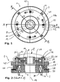
- the brake device 1 can be flanged to the housing of a drive unit via a base body 2 and fastening screws 4 (housing and drive unit are not shown).
- a shaft end protrudes from the drive unit through the base body 2 into the hub 8 of the brake disk 10, which is non-rotatably connected to the shaft end via a feather key connection 12.
- the brake disc is also fixed in the axial direction of the main axis 14 on the shaft end.
- the brake disk 10 lies with its flange region 16 between the brake flanges 18 and 20, which are arranged coaxially to the main body 2.
- the brake flanges 18 and 20 sit axially displaceable on stud bolts 22 which are fixed by threads in the base body 2.
- the axial movement range of the brake flanges 18 and 20 is fixed on the one hand by the transmission-facing end face of the main body 2 and the end faces of the stop nuts 24 facing the transmission.
- brake springs 26 are provided, which are supported between the pressure plate 28 and the brake flange 18.
- the position of the brake springs 26 is defined by corresponding recesses (not shown) in the pressure plate 28 and in the brake flange 18.
- the axial position of the pressure plate 28 is adjustable via an adjusting nut 30 which is coupled via a thread to the base body 2.
- suitable fixing elements for example screws
- the braking force is via the axial adjustment the adjusting nut 30 and thus the pressure plate 28 adjustable by the bias of the brake springs is changed accordingly.
- a plurality of through holes 32 are provided in the cylindrical brake lining elements 34 are used.
- the end faces of the brake lining elements run between the mutually facing radial surfaces 19 and 21 of the brake flanges 18 and 20. These radial surfaces 19 and 21 together with the end faces the friction pairings, which lead to the braking effect.
- the brake lining elements 34 can move axially in the through bores 32, so that no axial forces are transmitted to the flange region 16 of the brake disk 10.
- the brake pad elements 34 are clamped between the brake flanges 18 and 20 and thus put over their peripheral surfaces which are positively coupled to the through holes 32 of the flange portion 16 of the brake disc 10, the brake disc 10 and thus via the hub 8 and the feather key 12 to be braked shaft end firmly.
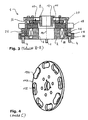
- the occurring circumferential forces on the brake flanges 18 and 20 are via anti-rotation 36 ( Fig. 3 ), with are screwed to the base body 2, transmitted to the base body 2 and the fastening screws 4 on the transmission housing.
- the studs 22 and the corresponding through holes in the brake flanges 18 and 20 are dimensioned so that no circumferential forces are transmitted here. That is, the studs 22 transmit only the actual braking force in the axial direction, while the resulting braking torque is transmitted via the anti-rotation 36.
- an electrically energizable armature coil 38 is provided in the base body 2, which magnetizes the base body 2 upon application of a corresponding voltage such that it attracts the brake flange 18 by overcoming the braking force and removes the frictional action between the radial surfaces 19 and 21 and the brake lining elements ,
- the stud bolts 22 surrounding coil springs 40 are provided between the brake flanges 18 and 20, which presses the brake flange 20 against the stop nuts 24 when dissolved (released brake).
- the brake flange 20 thus assumes regardless of the operating state (braked, loosened) and of the installation position of the brake device 1 always a defined axial position on the stop nuts 24 a.
- the brake disk 10 When the brake is released, the brake disk 10 is rotated again via the driven shaft end. As a result, the brake pad elements 34 are pressed by the centrifugal forces occurring outwardly into the through holes 32. The friction thus constructed prevents axial movement of the brake pad members 34 in the through holes 32. That is, the brake device 1 can be installed in any position without the braking or wear properties by different positions of the Brake lining elements 34 to the brake flanges 18 and 20 and the radial surfaces 19 and 21 would change.
- the brake lining elements 34 wear. That is, the original distance B between the end faces decreases with time to the distance b. Thus, the original brake gap s is greater and grows to the amount S (see Fig. 5 ). By this effect, the braking distance is extended and the brake springs 26 must continue to expand to overcome the brake gap S. This reduces the braking force and increases the brake application time. Both effects are undesirable.
- an adjustable spacer ring 42 is arranged on the outer surface of the brake flange 21, which is fastened fittingly via fastening screws 44 on the brake flange.
- keyhole-like recesses 46 are provided which surround the stop nuts 24 in its initial position (with new brake lining elements 34) with its wide portion 46 a. In this position, the brake flange 20 is supported with its outer radial surface in the region of the studs 22 directly on the stop nut 24.
- the spacer ring 42 can be achieved via the fastening elements 44 when the drive shaft is stationary and the brake is released. Subsequently, the brake flange 20 is pressed together with the spacer ring 42 overcoming the force applied by the coil springs 40 spreading force inside. In this case, also the brake lining elements 34 move axially in the through holes 32 and reduce the air gap to the brake flange 18. With appropriate wear is an axial displacement so far as possible that the spacer ring 42 with its outer radial surface completely so far "passes under" the stop nuts 24 that the spacer ring 42 is rotatable in the circumferential direction, so that its narrow portion 46 b can be moved under the stop nuts 24.
- the spacer ring 42 is rotatable in the circumferential direction.
- a spacer element (not shown) can be provided, which is formed transversely to the axis of rotation 14 slidably. Such a design may be easier to adjust in operation.
- brake disk 110 shows an alternative embodiment of the brake lining elements 134, which are not cylindrical here but prismatic, kidney-shaped and sit in corresponding through holes 106.
- the effective friction surface can be increased.
- other cross-sectional shapes of the brake lining elements can be realized.
- the in the 6 and 7 shown embodiment relates to a brake device 1 ', in which brake pads 34' are arranged on the brake flanges 18 'and 20', which act on an uncoated brake disc 10 '.
- This embodiment also shows an alternative coupling of the brake disc 10 'via a Dahlkant with the shaft end.
- the brake disc 10 'itself must be arranged axially displaceable on the shaft end to prevent constraining forces during braking.
- the wear compensation takes place here analogously via a corresponding spacer ring 42 ', ie, the compensation mechanism is suitable for braking devices 1', which have no axially displaceable brake lining elements 34, 134.
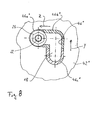
- Fig. 8 shows one of several adjustment of a spacer 42 "with a rectangular opening 46".
- a multi-stage readjustment can also be realized with a spacer element 42 "which can be linearly adjusted transversely to the axis of rotation.
- the recess 46 is formed as an angular guide slot of the stud bolt 22, so that a displacement in two different directions (transverse In this case, a first compensation can take place in a first displacement direction Z and a second compensation can take place in a second displacement direction Y (perpendicular to the first) .
- This embodiment allows a two-stage defined adjustment in which the respective adjustment process is in each case by a defined displacement.
- the adjustment is made one after the other from position 1 ( Fig. 8 ) in the position 2 against the stop of the transverse portion of the recess 42 "and then in position 3 against the end of this recess.
- the stud bolt 22 and the stop nut 24 are arranged in the region of the recess 46a "in position 1. In this position, the spacer element 42" does not act between the stop nuts 24 and the flange 18. Rather, the flange 18 itself bears against the stop nut.
- the spacer element 42 In position 2, the spacer element 42 "is displaced towards the stud bolts 22 and the stop nuts 24 in the direction Z, that the region 46b" below the stop nut 24 is arranged or, in other words, between the flange 18 and the surface facing the Stop nut 24 is located.
- the region 46b has a thickness D by which the air gap is reduced in this position.
- the spacer 42 " is displaced from the position 2 in the direction Y to the position 3.
- the region 46c" passes under the stop nut 24.
- the region 46c " has a thickness D 'which is greater as the thickness D in the region 46b ".
- the spacer ring 42, 42 'in the region of the openings 46, 46' may also be stepped, so that the Lsymmetrical spaltnachwolf can be done in several steps. It can also spacer rings 42, 42 'are used with different thicknesses D, which may also be used in combination.
Landscapes
- Engineering & Computer Science (AREA)
- General Engineering & Computer Science (AREA)
- Mechanical Engineering (AREA)
- Braking Arrangements (AREA)
- Valve Device For Special Equipments (AREA)
Claims (9)
- Dispositif de freinage (1, 1'), comportant un ensemble de disques de frein, dans lequel des garnitures de frein (34 ; 134 ; 34') sont disposées entre un premier et un deuxième flasque de frein (18, 20 ; 18', 20'), et une fente d'air (S) peut être réglée par plusieurs butées (22, 24), et un écarteur (42 ; 42' ; 42"), qui peut être déplacé transversalement à la direction de la force de freinage et peut être réglé de manière à agir en direction de la fente d'air, caractérisé en ce que l'écarteur (42 ; 42', 42") est réalisé de telle sorte qu'il peut être déplacé entre une première position, n'agissant pas sur la butée (22, 24 ; 22', 24'), et une deuxième position entre la butée (22, 24 ; 22', 24') et le flasque de frein (18, 20 ; 18', 20') agissant dans la direction de la force de freinage ou la direction de la fente d'air, de telle sorte que dans sa deuxième position, la fente d'air (S) est diminuée selon une dimension (D ; D') de l'écarteur, et permet ainsi de compenser une usure correspondante d'une garniture de frein (34 ; 134 ; 34').
- Dispositif de freinage (1, 1') selon la revendication 1, dans lequel l'écarteur (42 ; 42'; 42") est réalisé d'un seul tenant et comporte dans chaque cas un évidement (46 ; 46' ; 46") dans la zone des butées (22, 24), sachant que, dans la première position, lesdits évidements (46 ; 46' ; 46") entourent les butées (22, 24) avec une zone (46a ; 46a' ; 46a") et dans la deuxième position, une zone de bordure (46b ; 46b' ; 46b") de l'évidement (46 ; 46' ; 46") avec l'épaisseur (D ; D') est disposée axialement entre la butée (22, 24) et le flasque de frein (18, 20 ; 18', 20').
- Dispositif de freinage (1, 1') selon la revendication 1 ou 2, dans lequel l'écarteur (42 ; 42' ; 42") est disposé et réalisé de telle sorte que, pour sa fixation par l'intermédiaire d'un élément de fixation (44) dans sa première et/ou sa deuxième position, il peut être assemblé au flasque de frein (18, 20 ; 18', 20').
- Dispositif de freinage (1, 1') selon la revendication 1, 2 ou 3, dans lequel l'écarteur (42 ; 42' ; 42") est réalisé mobile dans une direction de réglage (Y, Z) transversalement à un axe (14) orienté dans la direction de la force de freinage.
- Dispositif de freinage (1, 1') selon la revendication 4, dans lequel l'écarteur (42 ; 42' ; 42") est réalisé sous la forme d'une bague rotative (42 ; 42') mobile autour de l'axe (14).
- Dispositif de freinage (1, 1') selon l'une quelconque des revendications 1 à 5, lequel comporte un disque de frein (10, 110) avec plusieurs garnitures de frein (34 ; 134), qui sont disposées dans des ouvertures (32 ; 132) traversant de part en part le disque de frein (10, 110).
- Dispositif de freinage (1, 1') selon la revendication 6, dans lequel les garnitures de frein (34 ; 134) sont disposées de manière mobile dans la direction d'une force de freinage.
- Dispositif de freinage (1, 1') selon la revendication 6 ou 7, dans lequel les garnitures de frein (34 ; 134) et les ouvertures (32 ; 132) ont une forme prismatique correspondant les unes aux autres.
- Dispositif de freinage (1, 1') selon la revendication 8, dans lequel les garnitures de frein (34) sont réniformes.
Applications Claiming Priority (2)
| Application Number | Priority Date | Filing Date | Title |
|---|---|---|---|
| DE102007014654A DE102007014654A1 (de) | 2007-03-27 | 2007-03-27 | Bremsscheibenanordnung |
| PCT/EP2008/002422 WO2008116651A1 (fr) | 2007-03-27 | 2008-03-27 | Élément d'écartement et dispositif de freinage |
Publications (2)
| Publication Number | Publication Date |
|---|---|
| EP2140164A1 EP2140164A1 (fr) | 2010-01-06 |
| EP2140164B1 true EP2140164B1 (fr) | 2010-08-18 |
Family
ID=39493327
Family Applications (1)
| Application Number | Title | Priority Date | Filing Date |
|---|---|---|---|
| EP08734809A Not-in-force EP2140164B1 (fr) | 2007-03-27 | 2008-03-27 | Élément d'écartement et dispositif de freinage |
Country Status (4)
| Country | Link |
|---|---|
| EP (1) | EP2140164B1 (fr) |
| AT (1) | ATE478273T1 (fr) |
| DE (2) | DE102007014654A1 (fr) |
| WO (1) | WO2008116651A1 (fr) |
Families Citing this family (4)
| Publication number | Priority date | Publication date | Assignee | Title |
|---|---|---|---|---|
| IT1391331B1 (it) * | 2008-10-03 | 2011-12-05 | Rossi Motoriduttori S P A | Freno elettromagnetico a molle |
| EP3480483B1 (fr) * | 2017-11-07 | 2025-12-24 | Ratier-Figeac SAS | Frein avec ensemble de retenue des poussières |
| WO2019097416A1 (fr) * | 2017-11-15 | 2019-05-23 | Gianluca Valieri | Système de frein à disque |
| DE102023118012A1 (de) * | 2023-07-07 | 2025-01-09 | Danfoss A/S | Abnutzungsausgleichsdistanzstück |
Family Cites Families (14)
| Publication number | Priority date | Publication date | Assignee | Title |
|---|---|---|---|---|
| SE333663B (fr) * | 1966-11-14 | 1971-03-22 | Asea Ab | |
| DE1964534U (de) * | 1967-04-18 | 1967-07-20 | Norddeutsche Bremsbandwerke Em | Reibklotz fuer bremsen und kupplungen. |
| DD111969A1 (fr) * | 1974-06-24 | 1975-03-12 | ||
| DD148250A1 (de) * | 1979-12-21 | 1981-05-13 | Heinrich Gebers | Elektromagnetisch schaltbare reibungsbremse |
| DE3338289C2 (de) | 1983-10-21 | 1987-05-07 | Maschinenfabrik Stromag Gmbh, 4750 Unna | Federdruckbetätigte und elektromagnetisch lüftbare Reibbremse |
| DE8519223U1 (de) | 1985-07-03 | 1985-10-31 | ABM Adam Baumüller GmbH Fabrik für Elektrotechnik in Marktredwitz, 8590 Marktredwitz | Zweistufige Magnetbremse für einen Elektromotor |
| CH682910A5 (fr) | 1990-04-19 | 1993-12-15 | Bobst Sa | Dispositif de registre par taquage longitudinal et latéral de feuille dans une machine de production d'emballages. |
| JPH09100850A (ja) * | 1995-10-04 | 1997-04-15 | Ogura Clutch Co Ltd | 無励磁作動形電磁ブレーキ |
| DE19819141C2 (de) * | 1997-05-01 | 2001-03-29 | Stromag Ag | Elektromagnetische Federdruckbremse |
| DE19737485C1 (de) | 1997-08-28 | 1999-06-17 | Stromag Ag | Elektromagnetisch betätigbare Bremse und Mehrfachbremsaggregat |
| EP1409885A1 (fr) * | 2001-02-21 | 2004-04-21 | Group Newtech International Inc. | Compensateur d'usure de freins |
| DE20303060U1 (de) * | 2003-02-25 | 2004-07-08 | Bubenzer Bremsen Gerhard Bubenzer Ing. Gmbh | Motoranbaubremse |
| WO2005038287A1 (fr) * | 2003-10-22 | 2005-04-28 | Groupe Newtech International Inc. | Systeme de compensation d'usure destine a un ensemble de frein a disque |
| DE202004020250U1 (de) * | 2004-12-31 | 2005-03-10 | Lenze Drive Systems Gmbh | Elektromagnetisch lüftbare Federkraftbremse mit Geräuschdämpfung |
-
2007
- 2007-03-27 DE DE102007014654A patent/DE102007014654A1/de not_active Ceased
-
2008
- 2008-03-27 DE DE502008001168T patent/DE502008001168D1/de active Active
- 2008-03-27 WO PCT/EP2008/002422 patent/WO2008116651A1/fr not_active Ceased
- 2008-03-27 AT AT08734809T patent/ATE478273T1/de active
- 2008-03-27 EP EP08734809A patent/EP2140164B1/fr not_active Not-in-force
Also Published As
| Publication number | Publication date |
|---|---|
| DE502008001168D1 (de) | 2010-09-30 |
| ATE478273T1 (de) | 2010-09-15 |
| DE102007014654A1 (de) | 2008-10-09 |
| WO2008116651A1 (fr) | 2008-10-02 |
| EP2140164A1 (fr) | 2010-01-06 |
Similar Documents
| Publication | Publication Date | Title |
|---|---|---|
| DE19830669B4 (de) | Bremsscheibe, insbesondere für ein Kraftfahrzeug | |
| EP1238204A1 (fr) | Ensemble disque de frein/moyeu pour freins a disque de vehicule | |
| DE19733169A1 (de) | Elektromagnetisch gelüftete Reibungs-Sicherheitsbremse mit zwei unabhängigen Bremskreisen | |
| EP0374268B1 (fr) | Dispositif pour le rattrapage automatique du jeu dans un assemblage d'embrayage et/ou de frein | |
| EP0639246A1 (fr) | Dispositif de commande avec rattrapage de jeu automatique pour freins a disque, notamment pour poids lourds et autobus. | |
| EP3830436B1 (fr) | Dispositif de palier | |
| EP2140164B1 (fr) | Élément d'écartement et dispositif de freinage | |
| DE10236295B4 (de) | Hoch-drehelastische Wellenkupplung und Verfahren zu ihrer Herstellung | |
| EP2776732A1 (fr) | Frein à disque, plaque de pression dudit frein à disque et garniture de frein dudit frein à disque | |
| EP1512881B1 (fr) | Dispositif d'embrayage | |
| EP2333249B1 (fr) | Carter central d'un turbocompresseur | |
| DE10254110B4 (de) | Bremsscheibe mit einem Reibring aus einem im wesentlichen nichtmetallischen Werkstoff | |
| DE102018006725A1 (de) | Elektromagnetisch betätigbare Bremsanordnung und Verfahren zur Inbetriebnahme oder Wartung einer elektromagnetisch betätigbaren Bremsanordnung | |
| EP1452764B1 (fr) | Frein à ressort avec dégagement électro-magnétique | |
| DE102014112662B4 (de) | Nachstellvorrichtung für eine drehhebelbetätigte Scheibenbremse, und Scheibenbremse mit einer solchen Nachstellvorrichtung | |
| WO2013110257A1 (fr) | Dispositif d'embrayage | |
| DE4211847C2 (de) | Bremsscheibe für Scheibenbremsen, insbesondere von Schienenfahrzeugen | |
| EP2410198A1 (fr) | Frein à disque pour un véhicule utilitaire | |
| EP0054734A1 (fr) | Dispositif de rattrapage de jeu dans une unité d'embrayage et/ou de frein à commande par électroaimant et par ressort | |
| EP3623655A1 (fr) | Palier avec dispositif de freinage | |
| DE102023118012A1 (de) | Abnutzungsausgleichsdistanzstück | |
| DE102005031753A1 (de) | Bremsträgeranordnung für eine Fahrzeugbremse | |
| WO2003029675A1 (fr) | Ensemble plaque de pression destine a un embrayage a friction | |
| DE102013212315B4 (de) | Verfahren zur Herstellung einer betätigbaren Kupplung | |
| EP1907718A1 (fr) | Systeme de levier pour embrayage a friction et embrayage a friction muni d'un tel systeme de levier |
Legal Events
| Date | Code | Title | Description |
|---|---|---|---|
| PUAI | Public reference made under article 153(3) epc to a published international application that has entered the european phase |
Free format text: ORIGINAL CODE: 0009012 |
|
| 17P | Request for examination filed |
Effective date: 20091015 |
|
| AK | Designated contracting states |
Kind code of ref document: A1 Designated state(s): AT BE BG CH CY CZ DE DK EE ES FI FR GB GR HR HU IE IS IT LI LT LU LV MC MT NL NO PL PT RO SE SI SK TR |
|
| GRAP | Despatch of communication of intention to grant a patent |
Free format text: ORIGINAL CODE: EPIDOSNIGR1 |
|
| DAX | Request for extension of the european patent (deleted) | ||
| GRAS | Grant fee paid |
Free format text: ORIGINAL CODE: EPIDOSNIGR3 |
|
| GRAA | (expected) grant |
Free format text: ORIGINAL CODE: 0009210 |
|
| AK | Designated contracting states |
Kind code of ref document: B1 Designated state(s): AT BE BG CH CY CZ DE DK EE ES FI FR GB GR HR HU IE IS IT LI LT LU LV MC MT NL NO PL PT RO SE SI SK TR |
|
| REG | Reference to a national code |
Ref country code: GB Ref legal event code: FG4D Free format text: NOT ENGLISH |
|
| REG | Reference to a national code |
Ref country code: CH Ref legal event code: NV Representative=s name: E. BLUM & CO. AG PATENT- UND MARKENANWAELTE VSP Ref country code: CH Ref legal event code: EP |
|
| REG | Reference to a national code |
Ref country code: IE Ref legal event code: FG4D Free format text: LANGUAGE OF EP DOCUMENT: GERMAN |
|
| REF | Corresponds to: |
Ref document number: 502008001168 Country of ref document: DE Date of ref document: 20100930 Kind code of ref document: P |
|
| REG | Reference to a national code |
Ref country code: SE Ref legal event code: TRGR |
|
| REG | Reference to a national code |
Ref country code: NL Ref legal event code: T3 |
|
| LTIE | Lt: invalidation of european patent or patent extension |
Effective date: 20100818 |
|
| PG25 | Lapsed in a contracting state [announced via postgrant information from national office to epo] |
Ref country code: NO Free format text: LAPSE BECAUSE OF FAILURE TO SUBMIT A TRANSLATION OF THE DESCRIPTION OR TO PAY THE FEE WITHIN THE PRESCRIBED TIME-LIMIT Effective date: 20101118 Ref country code: LT Free format text: LAPSE BECAUSE OF FAILURE TO SUBMIT A TRANSLATION OF THE DESCRIPTION OR TO PAY THE FEE WITHIN THE PRESCRIBED TIME-LIMIT Effective date: 20100818 |
|
| PG25 | Lapsed in a contracting state [announced via postgrant information from national office to epo] |
Ref country code: BG Free format text: LAPSE BECAUSE OF FAILURE TO SUBMIT A TRANSLATION OF THE DESCRIPTION OR TO PAY THE FEE WITHIN THE PRESCRIBED TIME-LIMIT Effective date: 20101118 Ref country code: PL Free format text: LAPSE BECAUSE OF FAILURE TO SUBMIT A TRANSLATION OF THE DESCRIPTION OR TO PAY THE FEE WITHIN THE PRESCRIBED TIME-LIMIT Effective date: 20100818 Ref country code: HR Free format text: LAPSE BECAUSE OF FAILURE TO SUBMIT A TRANSLATION OF THE DESCRIPTION OR TO PAY THE FEE WITHIN THE PRESCRIBED TIME-LIMIT Effective date: 20100818 Ref country code: SI Free format text: LAPSE BECAUSE OF FAILURE TO SUBMIT A TRANSLATION OF THE DESCRIPTION OR TO PAY THE FEE WITHIN THE PRESCRIBED TIME-LIMIT Effective date: 20100818 Ref country code: IS Free format text: LAPSE BECAUSE OF FAILURE TO SUBMIT A TRANSLATION OF THE DESCRIPTION OR TO PAY THE FEE WITHIN THE PRESCRIBED TIME-LIMIT Effective date: 20101218 Ref country code: CY Free format text: LAPSE BECAUSE OF FAILURE TO SUBMIT A TRANSLATION OF THE DESCRIPTION OR TO PAY THE FEE WITHIN THE PRESCRIBED TIME-LIMIT Effective date: 20100818 |
|
| REG | Reference to a national code |
Ref country code: IE Ref legal event code: FD4D |
|
| PG25 | Lapsed in a contracting state [announced via postgrant information from national office to epo] |
Ref country code: LV Free format text: LAPSE BECAUSE OF FAILURE TO SUBMIT A TRANSLATION OF THE DESCRIPTION OR TO PAY THE FEE WITHIN THE PRESCRIBED TIME-LIMIT Effective date: 20100818 Ref country code: GR Free format text: LAPSE BECAUSE OF FAILURE TO SUBMIT A TRANSLATION OF THE DESCRIPTION OR TO PAY THE FEE WITHIN THE PRESCRIBED TIME-LIMIT Effective date: 20101119 |
|
| PG25 | Lapsed in a contracting state [announced via postgrant information from national office to epo] |
Ref country code: IE Free format text: LAPSE BECAUSE OF FAILURE TO SUBMIT A TRANSLATION OF THE DESCRIPTION OR TO PAY THE FEE WITHIN THE PRESCRIBED TIME-LIMIT Effective date: 20100818 Ref country code: DK Free format text: LAPSE BECAUSE OF FAILURE TO SUBMIT A TRANSLATION OF THE DESCRIPTION OR TO PAY THE FEE WITHIN THE PRESCRIBED TIME-LIMIT Effective date: 20100818 |
|
| PG25 | Lapsed in a contracting state [announced via postgrant information from national office to epo] |
Ref country code: EE Free format text: LAPSE BECAUSE OF FAILURE TO SUBMIT A TRANSLATION OF THE DESCRIPTION OR TO PAY THE FEE WITHIN THE PRESCRIBED TIME-LIMIT Effective date: 20100818 Ref country code: RO Free format text: LAPSE BECAUSE OF FAILURE TO SUBMIT A TRANSLATION OF THE DESCRIPTION OR TO PAY THE FEE WITHIN THE PRESCRIBED TIME-LIMIT Effective date: 20100818 Ref country code: SK Free format text: LAPSE BECAUSE OF FAILURE TO SUBMIT A TRANSLATION OF THE DESCRIPTION OR TO PAY THE FEE WITHIN THE PRESCRIBED TIME-LIMIT Effective date: 20100818 Ref country code: CZ Free format text: LAPSE BECAUSE OF FAILURE TO SUBMIT A TRANSLATION OF THE DESCRIPTION OR TO PAY THE FEE WITHIN THE PRESCRIBED TIME-LIMIT Effective date: 20100818 |
|
| PLBE | No opposition filed within time limit |
Free format text: ORIGINAL CODE: 0009261 |
|
| STAA | Information on the status of an ep patent application or granted ep patent |
Free format text: STATUS: NO OPPOSITION FILED WITHIN TIME LIMIT |
|
| PG25 | Lapsed in a contracting state [announced via postgrant information from national office to epo] |
Ref country code: ES Free format text: LAPSE BECAUSE OF FAILURE TO SUBMIT A TRANSLATION OF THE DESCRIPTION OR TO PAY THE FEE WITHIN THE PRESCRIBED TIME-LIMIT Effective date: 20101129 |
|
| 26N | No opposition filed |
Effective date: 20110519 |
|
| REG | Reference to a national code |
Ref country code: DE Ref legal event code: R097 Ref document number: 502008001168 Country of ref document: DE Effective date: 20110519 |
|
| BERE | Be: lapsed |
Owner name: PINTSCH BUBENZER G.M.B.H. Effective date: 20110331 |
|
| PG25 | Lapsed in a contracting state [announced via postgrant information from national office to epo] |
Ref country code: MC Free format text: LAPSE BECAUSE OF NON-PAYMENT OF DUE FEES Effective date: 20110331 |
|
| PG25 | Lapsed in a contracting state [announced via postgrant information from national office to epo] |
Ref country code: BE Free format text: LAPSE BECAUSE OF NON-PAYMENT OF DUE FEES Effective date: 20110331 Ref country code: MT Free format text: LAPSE BECAUSE OF FAILURE TO SUBMIT A TRANSLATION OF THE DESCRIPTION OR TO PAY THE FEE WITHIN THE PRESCRIBED TIME-LIMIT Effective date: 20100818 |
|
| REG | Reference to a national code |
Ref country code: DE Ref legal event code: R082 Ref document number: 502008001168 Country of ref document: DE Representative=s name: MFG PATENTANWAELTE MEYER-WILDHAGEN MEGGLE-FREU, DE |
|
| PGFP | Annual fee paid to national office [announced via postgrant information from national office to epo] |
Ref country code: IT Payment date: 20120329 Year of fee payment: 5 |
|
| PGFP | Annual fee paid to national office [announced via postgrant information from national office to epo] |
Ref country code: FR Payment date: 20130329 Year of fee payment: 6 Ref country code: DE Payment date: 20130320 Year of fee payment: 6 Ref country code: SE Payment date: 20130319 Year of fee payment: 6 Ref country code: FI Payment date: 20130318 Year of fee payment: 6 Ref country code: GB Payment date: 20130318 Year of fee payment: 6 Ref country code: CH Payment date: 20130319 Year of fee payment: 6 |
|
| PG25 | Lapsed in a contracting state [announced via postgrant information from national office to epo] |
Ref country code: LU Free format text: LAPSE BECAUSE OF NON-PAYMENT OF DUE FEES Effective date: 20110327 |
|
| PGFP | Annual fee paid to national office [announced via postgrant information from national office to epo] |
Ref country code: NL Payment date: 20130318 Year of fee payment: 6 |
|
| PGFP | Annual fee paid to national office [announced via postgrant information from national office to epo] |
Ref country code: AT Payment date: 20130318 Year of fee payment: 6 |
|
| PG25 | Lapsed in a contracting state [announced via postgrant information from national office to epo] |
Ref country code: PT Free format text: LAPSE BECAUSE OF NON-PAYMENT OF DUE FEES Effective date: 20100818 |
|
| PG25 | Lapsed in a contracting state [announced via postgrant information from national office to epo] |
Ref country code: TR Free format text: LAPSE BECAUSE OF FAILURE TO SUBMIT A TRANSLATION OF THE DESCRIPTION OR TO PAY THE FEE WITHIN THE PRESCRIBED TIME-LIMIT Effective date: 20100818 |
|
| PG25 | Lapsed in a contracting state [announced via postgrant information from national office to epo] |
Ref country code: HU Free format text: LAPSE BECAUSE OF FAILURE TO SUBMIT A TRANSLATION OF THE DESCRIPTION OR TO PAY THE FEE WITHIN THE PRESCRIBED TIME-LIMIT Effective date: 20100818 |
|
| REG | Reference to a national code |
Ref country code: DE Ref legal event code: R119 Ref document number: 502008001168 Country of ref document: DE |
|
| REG | Reference to a national code |
Ref country code: NL Ref legal event code: V1 Effective date: 20141001 |
|
| PG25 | Lapsed in a contracting state [announced via postgrant information from national office to epo] |
Ref country code: FI Free format text: LAPSE BECAUSE OF NON-PAYMENT OF DUE FEES Effective date: 20140327 |
|
| REG | Reference to a national code |
Ref country code: CH Ref legal event code: PL |
|
| REG | Reference to a national code |
Ref country code: SE Ref legal event code: EUG |
|
| REG | Reference to a national code |
Ref country code: AT Ref legal event code: MM01 Ref document number: 478273 Country of ref document: AT Kind code of ref document: T Effective date: 20140327 |
|
| GBPC | Gb: european patent ceased through non-payment of renewal fee |
Effective date: 20140327 |
|
| PG25 | Lapsed in a contracting state [announced via postgrant information from national office to epo] |
Ref country code: SE Free format text: LAPSE BECAUSE OF NON-PAYMENT OF DUE FEES Effective date: 20140328 |
|
| REG | Reference to a national code |
Ref country code: FR Ref legal event code: ST Effective date: 20141128 |
|
| REG | Reference to a national code |
Ref country code: DE Ref legal event code: R119 Ref document number: 502008001168 Country of ref document: DE Effective date: 20141001 |
|
| PG25 | Lapsed in a contracting state [announced via postgrant information from national office to epo] |
Ref country code: DE Free format text: LAPSE BECAUSE OF NON-PAYMENT OF DUE FEES Effective date: 20141001 Ref country code: FR Free format text: LAPSE BECAUSE OF NON-PAYMENT OF DUE FEES Effective date: 20140331 Ref country code: LI Free format text: LAPSE BECAUSE OF NON-PAYMENT OF DUE FEES Effective date: 20140331 Ref country code: GB Free format text: LAPSE BECAUSE OF NON-PAYMENT OF DUE FEES Effective date: 20140327 Ref country code: CH Free format text: LAPSE BECAUSE OF NON-PAYMENT OF DUE FEES Effective date: 20140331 |
|
| PG25 | Lapsed in a contracting state [announced via postgrant information from national office to epo] |
Ref country code: AT Free format text: LAPSE BECAUSE OF NON-PAYMENT OF DUE FEES Effective date: 20140327 Ref country code: NL Free format text: LAPSE BECAUSE OF NON-PAYMENT OF DUE FEES Effective date: 20141001 |
|
| PG25 | Lapsed in a contracting state [announced via postgrant information from national office to epo] |
Ref country code: IT Free format text: LAPSE BECAUSE OF NON-PAYMENT OF DUE FEES Effective date: 20140327 |