EP2148226B1 - Dispositif de protection d'appareils optiques et/ou électroniques, télescope spatial doté d'un tel dispositif et dispositif amovible pour obturer une ouverture - Google Patents
Dispositif de protection d'appareils optiques et/ou électroniques, télescope spatial doté d'un tel dispositif et dispositif amovible pour obturer une ouverture Download PDFInfo
- Publication number
- EP2148226B1 EP2148226B1 EP08425508.2A EP08425508A EP2148226B1 EP 2148226 B1 EP2148226 B1 EP 2148226B1 EP 08425508 A EP08425508 A EP 08425508A EP 2148226 B1 EP2148226 B1 EP 2148226B1
- Authority
- EP
- European Patent Office
- Prior art keywords
- aperture
- protective device
- operating configuration
- edge
- elements
- Prior art date
- Legal status (The legal status is an assumption and is not a legal conclusion. Google has not performed a legal analysis and makes no representation as to the accuracy of the status listed.)
- Not-in-force
Links
- 230000003287 optical effect Effects 0.000 title claims description 11
- 230000001681 protective effect Effects 0.000 claims description 72
- 230000002093 peripheral effect Effects 0.000 claims description 10
- 230000002401 inhibitory effect Effects 0.000 claims 1
- 239000000243 solution Substances 0.000 description 11
- 230000005855 radiation Effects 0.000 description 9
- 239000003795 chemical substances by application Substances 0.000 description 3
- 239000012530 fluid Substances 0.000 description 3
- 238000011109 contamination Methods 0.000 description 2
- 238000002347 injection Methods 0.000 description 2
- 239000007924 injection Substances 0.000 description 2
- 230000004048 modification Effects 0.000 description 2
- 238000012986 modification Methods 0.000 description 2
- 229910000838 Al alloy Inorganic materials 0.000 description 1
- 229920000049 Carbon (fiber) Polymers 0.000 description 1
- 239000004917 carbon fiber Substances 0.000 description 1
- 239000000428 dust Substances 0.000 description 1
- 239000000446 fuel Substances 0.000 description 1
- 238000009434 installation Methods 0.000 description 1
- 239000000463 material Substances 0.000 description 1
- 239000003380 propellant Substances 0.000 description 1
- 238000007789 sealing Methods 0.000 description 1
- 238000000926 separation method Methods 0.000 description 1
- 238000004513 sizing Methods 0.000 description 1
- 230000007704 transition Effects 0.000 description 1
- 230000035899 viability Effects 0.000 description 1
Images


Classifications
-
- G—PHYSICS
- G02—OPTICS
- G02B—OPTICAL ELEMENTS, SYSTEMS OR APPARATUS
- G02B27/00—Optical systems or apparatus not provided for by any of the groups G02B1/00 - G02B26/00, G02B30/00
- G02B27/0006—Optical systems or apparatus not provided for by any of the groups G02B1/00 - G02B26/00, G02B30/00 with means to keep optical surfaces clean, e.g. by preventing or removing dirt, stains, contamination, condensation
-
- B—PERFORMING OPERATIONS; TRANSPORTING
- B64—AIRCRAFT; AVIATION; COSMONAUTICS
- B64G—COSMONAUTICS; VEHICLES OR EQUIPMENT THEREFOR
- B64G1/00—Cosmonautic vehicles
- B64G1/10—Artificial satellites; Systems of such satellites; Interplanetary vehicles
- B64G1/1021—Earth observation satellites
-
- B—PERFORMING OPERATIONS; TRANSPORTING
- B64—AIRCRAFT; AVIATION; COSMONAUTICS
- B64G—COSMONAUTICS; VEHICLES OR EQUIPMENT THEREFOR
- B64G1/00—Cosmonautic vehicles
- B64G1/22—Parts of, or equipment specially adapted for fitting in or to, cosmonautic vehicles
-
- B—PERFORMING OPERATIONS; TRANSPORTING
- B64—AIRCRAFT; AVIATION; COSMONAUTICS
- B64G—COSMONAUTICS; VEHICLES OR EQUIPMENT THEREFOR
- B64G1/00—Cosmonautic vehicles
- B64G1/22—Parts of, or equipment specially adapted for fitting in or to, cosmonautic vehicles
- B64G1/222—Parts of, or equipment specially adapted for fitting in or to, cosmonautic vehicles for deploying structures between a stowed and deployed state
- B64G1/2221—Parts of, or equipment specially adapted for fitting in or to, cosmonautic vehicles for deploying structures between a stowed and deployed state characterised by the manner of deployment
- B64G1/2227—Inflating
-
- B—PERFORMING OPERATIONS; TRANSPORTING
- B64—AIRCRAFT; AVIATION; COSMONAUTICS
- B64G—COSMONAUTICS; VEHICLES OR EQUIPMENT THEREFOR
- B64G1/00—Cosmonautic vehicles
- B64G1/22—Parts of, or equipment specially adapted for fitting in or to, cosmonautic vehicles
- B64G1/52—Protection, safety or emergency devices; Survival aids
- B64G1/54—Protection against radiation
-
- G—PHYSICS
- G02—OPTICS
- G02B—OPTICAL ELEMENTS, SYSTEMS OR APPARATUS
- G02B23/00—Telescopes, e.g. binoculars; Periscopes; Instruments for viewing the inside of hollow bodies; Viewfinders; Optical aiming or sighting devices
- G02B23/16—Housings; Caps; Mountings; Supports, e.g. with counterweight
-
- G—PHYSICS
- G02—OPTICS
- G02B—OPTICAL ELEMENTS, SYSTEMS OR APPARATUS
- G02B5/00—Optical elements other than lenses
- G02B5/005—Diaphragms
-
- G—PHYSICS
- G03—PHOTOGRAPHY; CINEMATOGRAPHY; ANALOGOUS TECHNIQUES USING WAVES OTHER THAN OPTICAL WAVES; ELECTROGRAPHY; HOLOGRAPHY
- G03B—APPARATUS OR ARRANGEMENTS FOR TAKING PHOTOGRAPHS OR FOR PROJECTING OR VIEWING THEM; APPARATUS OR ARRANGEMENTS EMPLOYING ANALOGOUS TECHNIQUES USING WAVES OTHER THAN OPTICAL WAVES; ACCESSORIES THEREFOR
- G03B9/00—Exposure-making shutters; Diaphragms
- G03B9/08—Shutters
- G03B9/10—Blade or disc rotating or pivoting about axis normal to its plane
-
- B—PERFORMING OPERATIONS; TRANSPORTING
- B64—AIRCRAFT; AVIATION; COSMONAUTICS
- B64G—COSMONAUTICS; VEHICLES OR EQUIPMENT THEREFOR
- B64G1/00—Cosmonautic vehicles
- B64G1/22—Parts of, or equipment specially adapted for fitting in or to, cosmonautic vehicles
- B64G1/52—Protection, safety or emergency devices; Survival aids
- B64G1/56—Protection against meteoroids or space debris
Definitions
- the present invention relates to a device for protecting optical and/or electronic apparatuses, in particular for space telescopes and more in particular it relates to a protective device, as defined in preamble of first claim.
- the present invention further relates to a space telescope and may be generally extended to a device for removably occluding an aperture.
- the document US 4460030 describes an example of a collapsible garage door which comprises a plurality of horizontal sections hinged together on opposite sides in alternate fashion.
- the object of the present invention is to overcome said drawbacks with reference to known art and provide and efficient and relatively economical solution, with reduced bulk and relatively reduced structural complexity.
- the present invention also relates to an apparatus and to a space telescope, as defined in claims 13 and 14, respectively.
- Protective device 1 of this example is in particular a screen device for optics of space telescopes, and preferably for optics of so called Large Telescopes. Therefore, the specific protective device 1 described herein is provided for installation on board of satellites and generally on board of space vehicles, in order to protect optics of telescopes provided on board said satellite or more generally on a space vehicle.
- a protective device 1 according to present invention may be employed also for protecting optical and/or electronic devices, other than the optics of a space telescope, since they may be for example used for protecting telecommunications equipments or other instruments, which are provided on board of satellites or space vehicles or more generally also in sectors, other than the space sector, for example for marine, aeronautical or terrestrial applications.
- a protective device according to present invention may be generally employed for various other applications, such as for an occlusion device for removably closing an aperture.
- protective device 1 is such as to removably close an aperture 2, through which equipment, such as optics 3 of a space telescope, for example a mirror-type or X-ray telescope, may be accessed.
- aperture 2 allows space telescope to receive an optical radiation entering from the outside, which radiation may cooperate with optics 3 of telescope, for example for space observations through said telescope, during its normal operation.
- aperture 2 is a circular aperture, whereas in other embodiments, aperture 2 may be differently shaped (see fig. 10 ). In fig. 1-3 , Z-Z is the axis of circular aperture 2.
- Protective device 1 is such as to attain a first operating configuration, or non-protective configuration, shown in fig. 1 , wherein device 1 allows accessing optics 3 through aperture 2, in this example, for allowing such optics to receive incoming optical radiation.
- the protective device 1 may further attain a second operating configuration, or protective configuration, shown in fig. 2 , wherein protective device 1 occludes aperture 2, for preventing access of optics 3 through aperture 2, for example for protecting such optics from exposition to potential damaging factors, like contamination by external agents (space dust, fuel residuals) or from optical radiation which may damage the same optics (for example direct solar radiation).
- protective device 1 occludes aperture 2, for preventing access of optics 3 through aperture 2, for example for protecting such optics from exposition to potential damaging factors, like contamination by external agents (space dust, fuel residuals) or from optical radiation which may damage the same optics (for example direct solar radiation).
- Protective device 1 comprises a support structure 4, 5, 6, comprising at least a supporting beam 5, which is transversely positioned with respect to aperture 2.
- support structure 4, 5, 6 comprises a plurality of radial beams 5, transversely positioned with respect to circular aperture 2, and more precisely eight radial beams 5.
- support structure 4, 5, 6 moreover comprises a central supporting element 4, which is positioned along Z-Z axis of aperture 2 and a tubular collar 6, which surrounds aperture 2.
- Supporting beams 5 comprise a first end portion, coupled to central supporting element 4, and an opposed second end portion, coupled to tubular collar 6, extending from central element 4 to tubular collar 6.
- Protective device 1 moreover comprises a plurality of covering elements S1, S2, said plurality comprising at least a pair of covering elements S1, S2, which are rotatably coupled to a same supporting beam 5.
- protective device 1 comprises eight pairs S1, S2 of covering elements, wherein covering elements of each pair S1, S2 are rotatably coupled, for example by means of one or more cylindrical hinges, to a respective supporting beam 5.
- each covering element of pair S1, S2 is hinged to a supporting beam 5 by means of a pair of cylindrical hinges 7, preferably of the type having radial clearance, so that each covering element S1, S2 has an internal lateral edge (with respect to pair S1, S2) which is fixed to supporting beam 5 and an opposed external lateral free edge 21, 22.
- lateral internal and external edges are radial edges.
- covering elements S1, S2 are panels, which are substantially opaque with respect to solar radiation and which have a multilayered structure (not shown in figures), with a central layer of aluminum alloy and preferably a honeycomb structure, which is interposed between two lateral plates, made of carbon fibers.
- a multilayered structure not shown in figures
- the shape of each covering element S1, S2 is a circular sector portion interposed between two radiuses of said sector.
- Protective device 1 further comprises actuator means for rotating panels S1, S2 between a first angular position and second angular position, respectively, for positioning protective device 1 in the non-protective operating configuration (shown in fig. 1 ) and in the protective operating configuration (shown in fig. 2 ).
- fig. 3 shows an intermediate operating condition, which is attained by protective device 1 at transition from protective operating configuration to non-protective operating configuration and vice-versa.
- first and second angular position of panels S1, S2 each of them rotates by approximately 90 degrees.
- panels S1, S2 are substantially perpendicular to plane of aperture 2, whereas in second angular position, they are substantially parallel to plane of aperture 2, in order to create, in combination with each other, a continuous closing screen 8 ( fig. 2 ) for aperture 2.
- Such continuous screen 8 of this particular example, shown in figures, is shaped like a circular sector comprised of 16 covering elements S1, S2, which are mutually adjacent and consecutive.
- Actuator means of panels S1, S2, which are not shown in figures, preferably comprise rotational actuators, more preferably of the pneumatic type.
- other types of actuator means may be provided, such as for example electric or electromagnetic motors.
- Such actuator means are preferably housed inside central element 4, which is therefore at least partially hollow.
- the protective device 1 moreover comprises an inflatable stiffening system for continuous closing screen 8, which may be activated for stiffening screen 8, once protective device 1 has attained its protective configuration.
- inflatable stiffening system preferably comprises tubular elastic conduits 10, which run parallel to supporting beams 5 and which may be pressurized in order to elastically deform and dilate.
- panels of a pair S1, S2 are each provided with an edge 11, 12, which is in an internal position with respect to same pair (i.e., it is directed towards supporting beam 5), and which is provided with a recess 13, 14.
- the two internal edges 11, 12 of panels S1, S2 may cooperate with each other, in order to define a channel for receiving the tubular conduit 10.
- conduit 10 By pressurizing this conduit 10 by means of a suitable fluid, for example a mono-phase gas, conduit 10 elastically deforms and expands inside recesses 13 and 14, in order to cooperate with panels S1, S2, exerting a pushing force on same panels, which therefore have a trend towards a slightly increased mutual distance.
- a suitable fluid for example a mono-phase gas
- conduit 10 elastically deforms and expands inside recesses 13 and 14, in order to cooperate with panels S1, S2, exerting a pushing force on same panels, which therefore have a trend towards a slightly increased mutual distance.
- Such separation is for instance accomplished by using hinges 7 ( fig. 2 ), provided with a radial clearance, for connecting panels S1, S2 to supporting beams 5.
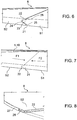
- tubular conduits 10 have a section which is approximately shaped like a triangle with rounded corners and curved sides.
- external edges 21, 22 of a pair of panels S1, S2 which are complementarily shaped with respect to respective external edges of panels of adjacent pairs S1, S2.
- the external edges 21, 22 of panel S1, S2 are meant to be the edges of same panel, which, in the protective condition of protective device 1, directly face the edge of panel S1, S2 of an adjacent pair of panels.
- protrusion 23 extending along edge 21, and the other comprises a continuous recess 24, extending along edge 22, which is counter-shaped with respect to protrusion 23.
- protrusion 23 has an asymmetrical profile and preferably centrally protrudes with respect to two lateral linear shoulders 25, 26. More preferably, protrusion 23 has a profile corresponding to a circumference evolvent.
- the inflatable stiffening system in order to further increase resistance of continuous screen 8 in the protective configuration, it is possible to provide the inflatable stiffening system with an inflatable peripheral conduit 27, which is associated with internal edge of aperture 2, for example by fixing it inside collar 6.
- This peripheral conduit 27 may be pressurized, when protective device 1 has achieved protective configuration, in order to cooperate with external peripheral edge of screen 8.
- peripheral edges of panels S1, S2 advantageously have a recess 28, so that peripheral edge of screen 8 is provided with a continuous peripheral recess 28 which may cooperate with peripheral inflatable conduit 27, when the latter is pressurized by a suitable fluid.
- the inflatable peripheral conduit 27 has a substantially " ⁇ "-shaped section, with a flat non inflatable band, which faces towards internal walls of collar 6 and an inflatable central part, which is fixed to the flat band and has a substantially circular section.
- protective device 1 In the following, an example of operation of protective device 1 will be briefly described, with specific reference to the case, where device 1 is installed on board a space telescope, in order to protect the optics of such a telescope.
- protective device 1 During launch phase and initial orbit injection of satellite, it is important to protect optics against contaminating agents, such as propellant residuals. For this reason, during these phases, protective device 1 will be in protective condition ( fig. 2 ), wherein panels S1, S2 are oriented in order to form a protective screen 8, which inhibits contact between optics and such agents. Since during these phases, screen 8 is subject to heavy launch stresses, it is particularly advantageous to stiffen screen 8 by pressurizing said inflatable stiffening system.
- the inflatable stiffening system may be depressurized, allowing the protective device to attain its non-protective configuration ( fig. 1 ), for example during normal operations of telescope, in order to undertake space observations.
- the protective device 1 may be returned to its protective configuration.
- the inflatable stiffening system since screen 8 will usually be free of loads and usually no particular stress will act upon it.
- this stiffening system is also a sealing system, it may be decided to pressurize the system in particularly hostile environments, for example if presence of high density of space detritus is detected.
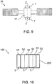
- the proposed solution is particularly advantageous when, as shown in fig. 9 , two protective devices 1 of the above said type need to be associated to a satellite 30 comprising a space telescope 31, for example of the mirror type, for the upper portion and lower portion of telescope optics, respectively.
- fig. 10 schematically shows a device 100 for removably closing a rectangular aperture 200, wherein the supporting beams 5 are parallel to each other and each supporting beam 5 is rotatably coupled to a pair of rectangularly shaped panels S1, S2.
- all of above teachings referring to an inflatable stiffening system may be applied, with slight modifications, which are all known to the skilled in the art, to the protective device 100 of fig. 10 .
Landscapes
- Engineering & Computer Science (AREA)
- Physics & Mathematics (AREA)
- Remote Sensing (AREA)
- General Physics & Mathematics (AREA)
- Aviation & Aerospace Engineering (AREA)
- Astronomy & Astrophysics (AREA)
- Optics & Photonics (AREA)
- Health & Medical Sciences (AREA)
- General Health & Medical Sciences (AREA)
- Toxicology (AREA)
- Critical Care (AREA)
- Emergency Medicine (AREA)
- Telescopes (AREA)
Claims (13)
- Dispositif d'obturation (1) permettant de fermer de manière amovible une ouverture (2), ledit dispositif (1) étant capable d'adopter des première et deuxième configurations de fonctionnement, respectivement, permettant de laisser ladite ouverture au moins partiellement ouverte et de fermer ladite ouverture, de sorte qu'il comprend :- une structure de support comprenant au moins une poutre de support (5) qui est positionnée de manière transversale par rapport à l'ouverture (2) ;- une pluralité d'éléments de couverture (S1, S2) comprenant au moins une paire (S1, S2) d'éléments, chaque élément de couverture (S1, S2) présentant un bord latéral interne (11, 12) qui est couplé rotatif à la poutre de support (5) et un bord libre latéral externe (21, 22) opposé ;- un moyen d'actionnement permettant de faire tourner les éléments de couverture (S1, S2) autour de la poutre de support (5) entre des première et deuxième positions angulaires, afin que le dispositif (1) atteigne la première ou la deuxième configuration de fonctionnement, respectivement, dans lequel, dans la deuxième configuration de fonctionnement, les éléments de couverture (S1, S2) sont tels qu'ils définissent ensemble un écran (8) destiné à l'ouverture (2) ; etcaractérisé en ce qu'il comprend en outre :- un système de rigidification gonflable (10, 27), qui peut être activé afin de rigidifier l'écran (8) dans la deuxième configuration de fonctionnement.
- Dispositif de protection (1) pour des appareils optiques et/ou électroniques (3), dans lequel le dispositif (1) est fourni pour fermer de manière amovible une ouverture (2) à travers laquelle il est possible d'accéder à des appareils (3), le dispositif (1) étant en mesure d'atteindre des première et deuxième configurations de fonctionnement afin de permettre ou d'empêcher, respectivement, un accès à des appareils (3) à travers ladite ouverture (2), caractérisé en ce qu'il comprend un dispositif d'obturation (1) selon la revendication 1.
- Dispositif de protection (1) selon la revendication 2, comprenant une pluralité desdites poutres de support (5) et une pluralité de paires d'éléments de couverture, dans lequel chaque paire (S1, S2) comprend des éléments de couverture qui sont couplés rotatifs à une poutre (5) respective.
- Dispositif de protection (1) selon la revendication 3, dans lequel l'ouverture (2) est une ouverture circulaire et dans lequel des poutres de support (5) sont positionnées de manière radiale par rapport à l'ouverture.
- Dispositif de protection (1) selon la revendication 4, dans lequel le moyen de support (4, 5, 6) comprend en outre un élément de support central (4) qui est positionné de manière axiale par rapport à l'ouverture (2), et un collier tubulaire (6) entourant l'ouverture (2), dans lequel des poutres de support (5) s'étendent à partir dudit élément de support central (4) vers ledit collier (6).
- Dispositif de protection (1) selon l'une quelconque des revendications 2 à 5, dans lequel des éléments de couverture (SI, S2), dans la deuxième position angulaire, sont agencés dans un plan qui est essentiellement parallèle à l'ouverture (2), et, dans la première position angulaire, sont perpendiculaires audit plan.
- Dispositif de protection (1) selon l'une quelconque des revendications 2 à 6, dans lequel le système de rigidification gonflable (10, 27) comprend au moins un conduit élastique (10) qui s'étend parallèlement à ladite poutre (5), et qui, dans la deuxième configuration de fonctionnement, s'interpose entre ladite paire d'éléments de couverture (S1, S2) et peut être mis sous pression afin de se dilater entre des éléments de ladite paire.
- Dispositif de protection (1) selon la revendication 7, comprenant des première et deuxième paires adjacentes d'éléments de couverture (S1, S2), dans lequel des éléments de couverture de la première paire sont couplés rotatifs à une première poutre de support (5) et des éléments de la deuxième paire sont couplés rotatifs à une deuxième poutre de support (5), les éléments étant mis en forme de telle manière que deux éléments desdites paires qui sont interposés entre lesdites première et deuxième poutres de support sont munis d'un premier bord (21) et d'un deuxième bord (22) qui se font face l'un l'autre afin d'interférer mutuellement lorsque le dispositif (1) atteint la deuxième configuration de fonctionnement.
- Dispositif de protection (1) selon la revendication 8, dans lequel lesdits premier (21) et deuxième (22) bords sont mis en forme de manière complémentaire afin de s'imbriquer l'un dans l'autre dans la deuxième configuration de fonctionnement.
- Dispositif de protection (1) selon la revendication 9, dans lequel l'un parmi lesdits bords est muni d'une saillie continue, s'étendant le long dudit bord, et l'autre parmi lesdits bords est muni d'un renfoncement continu s'étendant le long dudit bord.
- Dispositif de protection (1) selon l'une quelconque des revendications 6 à 10, dans lequel le système de rigidification gonflable comprend en outre un conduit gonflable périphérique (27) qui est associé à un bord interne de l'ouverture (2), et qui peut être mis sous pression, lorsque le dispositif de protection (1) a atteint la deuxième configuration de fonctionnement, afin de coopérer avec un bord périphérique externe (28) de l'écran (8).
- Appareil comprenant au moins un dispositif de protection (1) selon l'une quelconque des revendications 2 à 11.
- Télescope spatial comprenant au moins un dispositif de protection (1) selon l'une quelconque des revendications 2 à 11.
Priority Applications (3)
| Application Number | Priority Date | Filing Date | Title |
|---|---|---|---|
| EP08425508.2A EP2148226B1 (fr) | 2008-07-25 | 2008-07-25 | Dispositif de protection d'appareils optiques et/ou électroniques, télescope spatial doté d'un tel dispositif et dispositif amovible pour obturer une ouverture |
| ES08425508.2T ES2637343T3 (es) | 2008-07-25 | 2008-07-25 | Dispositivo para la protección de aparatos ópticos y/o electrónicos, telescopio espacial que comprende dicho dispositivo y dispositivo para ocluir de forma amovible una abertura |
| US12/508,767 US8064154B2 (en) | 2008-07-25 | 2009-07-24 | Device for protecting optical and/or electronic apparatuses, space telescope comprising said device, and device for removably occluding an aperture |
Applications Claiming Priority (1)
| Application Number | Priority Date | Filing Date | Title |
|---|---|---|---|
| EP08425508.2A EP2148226B1 (fr) | 2008-07-25 | 2008-07-25 | Dispositif de protection d'appareils optiques et/ou électroniques, télescope spatial doté d'un tel dispositif et dispositif amovible pour obturer une ouverture |
Publications (2)
| Publication Number | Publication Date |
|---|---|
| EP2148226A1 EP2148226A1 (fr) | 2010-01-27 |
| EP2148226B1 true EP2148226B1 (fr) | 2017-06-28 |
Family
ID=40070970
Family Applications (1)
| Application Number | Title | Priority Date | Filing Date |
|---|---|---|---|
| EP08425508.2A Not-in-force EP2148226B1 (fr) | 2008-07-25 | 2008-07-25 | Dispositif de protection d'appareils optiques et/ou électroniques, télescope spatial doté d'un tel dispositif et dispositif amovible pour obturer une ouverture |
Country Status (3)
| Country | Link |
|---|---|
| US (1) | US8064154B2 (fr) |
| EP (1) | EP2148226B1 (fr) |
| ES (1) | ES2637343T3 (fr) |
Families Citing this family (9)
| Publication number | Priority date | Publication date | Assignee | Title |
|---|---|---|---|---|
| US8186628B2 (en) * | 2009-08-12 | 2012-05-29 | Raytheon Company | Multi-axis articulated solar light shade for space-based sensors |
| FR2974348B1 (fr) * | 2011-04-21 | 2014-01-24 | Thales Sa | Dispositif de protection d'un instrument optique d'un satellite |
| CN102662232B (zh) * | 2012-03-09 | 2014-01-15 | 中国科学院长春光学精密机械与物理研究所 | 一种电动大口径望远镜主镜保护盖 |
| US8973641B1 (en) | 2012-10-31 | 2015-03-10 | Space Systems/Loral, Llc | Roll-up contamination cover |
| CN104443442B (zh) * | 2013-09-24 | 2017-05-17 | 上海空间电源研究所 | 空间产品的防护结构及设置方法 |
| CN105151324A (zh) * | 2015-09-22 | 2015-12-16 | 上海卫星工程研究所 | 天基成像雷达卫星原子氧遮蔽装置及其使用方法 |
| FR3117458B1 (fr) * | 2020-12-16 | 2023-04-21 | Thales Sa | Dispositif de protection d’un instrument optique d’un satellite |
| US11926442B2 (en) | 2021-04-07 | 2024-03-12 | Ball Aerospace & Technologies Corp. | Multiple function spacecraft sunshade systems and methods |
| TR2022013588A1 (tr) * | 2022-08-31 | 2024-03-21 | Tusas Tuerk Havacilik Ve Uzay Sanayii Anonim Sirketi | Bir termal koruma sistemi. |
Citations (1)
| Publication number | Priority date | Publication date | Assignee | Title |
|---|---|---|---|---|
| US4935129A (en) * | 1989-03-20 | 1990-06-19 | Wang Kung Hsi | Closure device for a scupper drain |
Family Cites Families (15)
| Publication number | Priority date | Publication date | Assignee | Title |
|---|---|---|---|---|
| US2938749A (en) * | 1956-01-20 | 1960-05-31 | Gen Motors Corp | Vehicle closure and operating mechanism therefor |
| US2995997A (en) * | 1957-05-02 | 1961-08-15 | Optische Ind De Oude Delft Nv | Mirror camera provided with a diaphragm |
| GB930578A (en) * | 1960-10-12 | 1963-07-03 | Parsons & Co Sir Howard G | Improvements in and relating to reflecting telescopes |
| US3216760A (en) * | 1963-04-26 | 1965-11-09 | Gen Motors Corp | Vehicle body closure |
| US3850504A (en) | 1972-12-20 | 1974-11-26 | Itek Corp | Telescope with inflatable door |
| US4045117A (en) * | 1976-04-23 | 1977-08-30 | Jack Lerner | Combined camera lens cap and lens shade |
| US4295706A (en) * | 1979-07-30 | 1981-10-20 | Frost George H | Combined lens cap and sunshade for a camera |
| US4460030A (en) | 1982-09-29 | 1984-07-17 | Chamberlain Manufacturing Corporation | Collapsible garage door |
| JPH0790695B2 (ja) * | 1989-09-26 | 1995-10-04 | 株式会社大井製作所 | ルーフドアの開閉装置 |
| FR2666159B1 (fr) | 1990-08-22 | 1992-12-11 | Aerospatiale | Dispositif bistable sans frottement pour usage spatial, notamment pour l'obturation d'un orifice d'entree d'un instrument optique spatial. |
| JP2999674B2 (ja) * | 1994-09-30 | 2000-01-17 | 富士写真光機株式会社 | 自動開閉レンズカバーを備えた望遠鏡 |
| US7144123B2 (en) | 2003-04-09 | 2006-12-05 | Lundgren Mark A | Space optics cover and extendable baffle for contamination control |
| US7464900B2 (en) * | 2004-10-20 | 2008-12-16 | The Boeing Company | Folding retractable protective dome for space vehicle equipment |
| US7557995B1 (en) * | 2006-07-11 | 2009-07-07 | Itt Manufacturing Enterprises, Inc. | Deployable telescope shade |
| US7828450B2 (en) * | 2007-09-23 | 2010-11-09 | Lou Riley | Adjustable sunshade assembly |
-
2008
- 2008-07-25 EP EP08425508.2A patent/EP2148226B1/fr not_active Not-in-force
- 2008-07-25 ES ES08425508.2T patent/ES2637343T3/es active Active
-
2009
- 2009-07-24 US US12/508,767 patent/US8064154B2/en not_active Expired - Fee Related
Patent Citations (1)
| Publication number | Priority date | Publication date | Assignee | Title |
|---|---|---|---|---|
| US4935129A (en) * | 1989-03-20 | 1990-06-19 | Wang Kung Hsi | Closure device for a scupper drain |
Also Published As
| Publication number | Publication date |
|---|---|
| EP2148226A1 (fr) | 2010-01-27 |
| US8064154B2 (en) | 2011-11-22 |
| US20100284078A1 (en) | 2010-11-11 |
| ES2637343T3 (es) | 2017-10-11 |
Similar Documents
| Publication | Publication Date | Title |
|---|---|---|
| EP2148226B1 (fr) | Dispositif de protection d'appareils optiques et/ou électroniques, télescope spatial doté d'un tel dispositif et dispositif amovible pour obturer une ouverture | |
| Parshley et al. | CCAT-prime: a novel telescope for sub-millimeter astronomy | |
| EP2151704B1 (fr) | Dispositif de blindage pour appareils optiques et/ou électroniques, et véhicule spatial comprenant ledit dispositif | |
| RU2561648C2 (ru) | Устройство для размещения штанг створок реверсора тяги на неподвижном внутреннем элементе гондолы турбореактивного двигателя | |
| CN102745346B (zh) | 用于保护卫星光学仪器的装置 | |
| Mroczkowski et al. | The conceptual design of the 50-meter atacama large aperture submillimeter telescope (atlast) | |
| EP2743187B1 (fr) | Engin spatial pourvu d'au moins une structure de panneau déployable et structure de panneau déployable | |
| US5530200A (en) | Three-phase metal-clad electricity line, and method of manufacture | |
| CA2812448C (fr) | Antenne a reflecteurs multiples pour satellites de telecommunications | |
| US20250314220A1 (en) | Seal for gimbaling and/or fixed rocket engine nozzles, and associated systems and methods | |
| US20060081343A1 (en) | Retractable protective dome for space vehicle equipment | |
| Marchiori et al. | ELT design status: the most powerful ground telescope | |
| Herbst et al. | Installation and commissioning of the LINC-NIRVANA near-infrared MCAO imager on LBT | |
| AU709921B2 (en) | Method and arrangement for low-pressure locking of a gas-filled device | |
| Busatta et al. | Innovative enclosure dome/observing aperture system design for the MROI Array Telescopes | |
| Lécossais et al. | Deployable panel radiator | |
| van Casteren | X-ray multimirror spacecraft: a large telescope | |
| Gressler et al. | The LSST dome: manufacturing and erection status | |
| KR102432728B1 (ko) | 단열 패널 | |
| DK3194881T3 (en) | WITHDRAWAL VIEW SYSTEM | |
| EP4667366A1 (fr) | Ensemble de désorbite et de protection thermique destiné à être appliqué à des satellites cubes | |
| KR102835428B1 (ko) | 보호기능을 구비한 이중 대역 파라볼릭 안테나 시스템 | |
| CN113772136B (zh) | 基于多空间机器人系统的超大型太空望远镜在轨维护方法 | |
| Marchiori et al. | Dogu Anadolu Gözlemevi (DAG) integrated dome and telescope on-site assembly | |
| EP4731520A1 (fr) | Appareil de déplacement pour satellite artificiel |
Legal Events
| Date | Code | Title | Description |
|---|---|---|---|
| PUAI | Public reference made under article 153(3) epc to a published international application that has entered the european phase |
Free format text: ORIGINAL CODE: 0009012 |
|
| AK | Designated contracting states |
Kind code of ref document: A1 Designated state(s): AT BE BG CH CY CZ DE DK EE ES FI FR GB GR HR HU IE IS IT LI LT LU LV MC MT NL NO PL PT RO SE SI SK TR |
|
| AX | Request for extension of the european patent |
Extension state: AL BA MK RS |
|
| 17P | Request for examination filed |
Effective date: 20100622 |
|
| AKX | Designation fees paid |
Designated state(s): DE ES FR GB IT NL |
|
| 17Q | First examination report despatched |
Effective date: 20160823 |
|
| GRAP | Despatch of communication of intention to grant a patent |
Free format text: ORIGINAL CODE: EPIDOSNIGR1 |
|
| INTG | Intention to grant announced |
Effective date: 20170307 |
|
| GRAS | Grant fee paid |
Free format text: ORIGINAL CODE: EPIDOSNIGR3 |
|
| GRAA | (expected) grant |
Free format text: ORIGINAL CODE: 0009210 |
|
| AK | Designated contracting states |
Kind code of ref document: B1 Designated state(s): DE ES FR GB IT NL |
|
| REG | Reference to a national code |
Ref country code: GB Ref legal event code: FG4D Ref country code: FR Ref legal event code: PLFP Year of fee payment: 10 |
|
| REG | Reference to a national code |
Ref country code: DE Ref legal event code: R096 Ref document number: 602008050853 Country of ref document: DE |
|
| REG | Reference to a national code |
Ref country code: NL Ref legal event code: FP |
|
| REG | Reference to a national code |
Ref country code: ES Ref legal event code: FG2A Ref document number: 2637343 Country of ref document: ES Kind code of ref document: T3 Effective date: 20171011 |
|
| REG | Reference to a national code |
Ref country code: DE Ref legal event code: R097 Ref document number: 602008050853 Country of ref document: DE |
|
| PLBE | No opposition filed within time limit |
Free format text: ORIGINAL CODE: 0009261 |
|
| STAA | Information on the status of an ep patent application or granted ep patent |
Free format text: STATUS: NO OPPOSITION FILED WITHIN TIME LIMIT |
|
| 26N | No opposition filed |
Effective date: 20180329 |
|
| REG | Reference to a national code |
Ref country code: FR Ref legal event code: PLFP Year of fee payment: 11 |
|
| PGFP | Annual fee paid to national office [announced via postgrant information from national office to epo] |
Ref country code: FR Payment date: 20200625 Year of fee payment: 13 |
|
| PGFP | Annual fee paid to national office [announced via postgrant information from national office to epo] |
Ref country code: NL Payment date: 20200715 Year of fee payment: 13 |
|
| PGFP | Annual fee paid to national office [announced via postgrant information from national office to epo] |
Ref country code: DE Payment date: 20200714 Year of fee payment: 13 Ref country code: GB Payment date: 20200715 Year of fee payment: 13 |
|
| PGFP | Annual fee paid to national office [announced via postgrant information from national office to epo] |
Ref country code: IT Payment date: 20200625 Year of fee payment: 13 |
|
| REG | Reference to a national code |
Ref country code: ES Ref legal event code: FD2A Effective date: 20201201 |
|
| PG25 | Lapsed in a contracting state [announced via postgrant information from national office to epo] |
Ref country code: ES Free format text: LAPSE BECAUSE OF NON-PAYMENT OF DUE FEES Effective date: 20190726 |
|
| REG | Reference to a national code |
Ref country code: DE Ref legal event code: R119 Ref document number: 602008050853 Country of ref document: DE |
|
| REG | Reference to a national code |
Ref country code: NL Ref legal event code: MM Effective date: 20210801 |
|
| GBPC | Gb: european patent ceased through non-payment of renewal fee |
Effective date: 20210725 |
|
| PG25 | Lapsed in a contracting state [announced via postgrant information from national office to epo] |
Ref country code: GB Free format text: LAPSE BECAUSE OF NON-PAYMENT OF DUE FEES Effective date: 20210725 Ref country code: DE Free format text: LAPSE BECAUSE OF NON-PAYMENT OF DUE FEES Effective date: 20220201 |
|
| PG25 | Lapsed in a contracting state [announced via postgrant information from national office to epo] |
Ref country code: NL Free format text: LAPSE BECAUSE OF NON-PAYMENT OF DUE FEES Effective date: 20210801 Ref country code: FR Free format text: LAPSE BECAUSE OF NON-PAYMENT OF DUE FEES Effective date: 20210731 |
|
| PG25 | Lapsed in a contracting state [announced via postgrant information from national office to epo] |
Ref country code: IT Free format text: LAPSE BECAUSE OF NON-PAYMENT OF DUE FEES Effective date: 20210725 |