EP2157028A1 - Entnahmearmatur mit einem Armaturengehäuse aus Kunststoff für Transport- und Lagerbehälter für Flüssigkeiten - Google Patents
Entnahmearmatur mit einem Armaturengehäuse aus Kunststoff für Transport- und Lagerbehälter für Flüssigkeiten Download PDFInfo
- Publication number
- EP2157028A1 EP2157028A1 EP09008104A EP09008104A EP2157028A1 EP 2157028 A1 EP2157028 A1 EP 2157028A1 EP 09008104 A EP09008104 A EP 09008104A EP 09008104 A EP09008104 A EP 09008104A EP 2157028 A1 EP2157028 A1 EP 2157028A1
- Authority
- EP
- European Patent Office
- Prior art keywords
- plastic
- flange
- transport
- connecting flange
- removal fitting
- Prior art date
- Legal status (The legal status is an assumption and is not a legal conclusion. Google has not performed a legal analysis and makes no representation as to the accuracy of the status listed.)
- Granted
Links
Images


Classifications
-
- B—PERFORMING OPERATIONS; TRANSPORTING
- B65—CONVEYING; PACKING; STORING; HANDLING THIN OR FILAMENTARY MATERIAL
- B65D—CONTAINERS FOR STORAGE OR TRANSPORT OF ARTICLES OR MATERIALS, e.g. BAGS, BARRELS, BOTTLES, BOXES, CANS, CARTONS, CRATES, DRUMS, JARS, TANKS, HOPPERS, FORWARDING CONTAINERS; ACCESSORIES, CLOSURES, OR FITTINGS THEREFOR; PACKAGING ELEMENTS; PACKAGES
- B65D77/00—Packages formed by enclosing articles or materials in preformed containers, e.g. boxes, cartons, sacks or bags
- B65D77/04—Articles or materials enclosed in two or more containers disposed one within another
- B65D77/0446—Articles or materials enclosed in two or more containers disposed one within another the inner and outer containers being rigid or semi-rigid and the outer container being of polygonal cross-section not formed by folding or erecting one or more blanks
- B65D77/0453—Articles or materials enclosed in two or more containers disposed one within another the inner and outer containers being rigid or semi-rigid and the outer container being of polygonal cross-section not formed by folding or erecting one or more blanks the inner container having a polygonal cross-section
- B65D77/0466—Articles or materials enclosed in two or more containers disposed one within another the inner and outer containers being rigid or semi-rigid and the outer container being of polygonal cross-section not formed by folding or erecting one or more blanks the inner container having a polygonal cross-section the containers being mounted on a pallet
-
- B—PERFORMING OPERATIONS; TRANSPORTING
- B67—OPENING, CLOSING OR CLEANING BOTTLES, JARS OR SIMILAR CONTAINERS; LIQUID HANDLING
- B67D—DISPENSING, DELIVERING OR TRANSFERRING LIQUIDS, NOT OTHERWISE PROVIDED FOR
- B67D7/00—Apparatus or devices for transferring liquids from bulk storage containers or reservoirs into vehicles or into portable containers, e.g. for retail sale purposes
- B67D7/06—Details or accessories
- B67D7/32—Arrangements of safety or warning devices; Means for preventing unauthorised delivery of liquid
- B67D7/3236—Arrangements of safety or warning devices; Means for preventing unauthorised delivery of liquid relating to electrostatic charges
-
- B—PERFORMING OPERATIONS; TRANSPORTING
- B01—PHYSICAL OR CHEMICAL PROCESSES OR APPARATUS IN GENERAL
- B01D—SEPARATION
- B01D2201/00—Details relating to filtering apparatus
- B01D2201/50—Means for dissipating electrostatic charges
-
- B—PERFORMING OPERATIONS; TRANSPORTING
- B65—CONVEYING; PACKING; STORING; HANDLING THIN OR FILAMENTARY MATERIAL
- B65D—CONTAINERS FOR STORAGE OR TRANSPORT OF ARTICLES OR MATERIALS, e.g. BAGS, BARRELS, BOTTLES, BOXES, CANS, CARTONS, CRATES, DRUMS, JARS, TANKS, HOPPERS, FORWARDING CONTAINERS; ACCESSORIES, CLOSURES, OR FITTINGS THEREFOR; PACKAGING ELEMENTS; PACKAGES
- B65D2213/00—Safety means
- B65D2213/02—Means for preventing buil-up of electrostatic charges
-
- H—ELECTRICITY
- H05—ELECTRIC TECHNIQUES NOT OTHERWISE PROVIDED FOR
- H05F—STATIC ELECTRICITY; NATURALLY-OCCURRING ELECTRICITY
- H05F3/00—Carrying-off electrostatic charges
Definitions
- the invention relates to a removal fitting with a valve body made of plastic, in particular flap or ball valve, for transport and storage containers for liquids, with an inner container made of plastic with a closable filler neck and a discharge nozzle for connecting the sampling valve, an outer sheath of metal mesh or metal sheet and a pallet-like base made of metal or an at least partially electrically conductive plastic for supporting the inner container are equipped.
- a grounding member which is formed as a curved metal sheet or plate, which extends over a portion of the inner bore of the removal fitting and a mounting screw and a ground wire is connected to the base of the container.
- the invention has for its object to further develop the generic removal fitting for transport and storage containers for liquids with a view to a secure and comprehensive grounding for the derivation of the forming during filling with liquids and in the removal of liquids due to fluid friction electric charges and low-cost production ,
- the removal fitting according to the invention the housing having a connection flange of electrically conductive plastic for welding the housing to the discharge neck of the plastic inner container equipped with an outer sheath of metal mesh or sheet metal and with a pallet-like base made of electrically conductive material Transport and storage container for liquids, allows a safe electrical grounding of leaking from the inner container during emptying liquid via an electrical grounding conductor, which connects the connection flange with the pallet-like base frame or the outer shell.
- the removal fitting with the connection flange of electrically conductive plastic is much cheaper than the removal fitting according to the prior art, the entire plastic housing is equipped antistatic.
- FIG. 1 has as main components a replaceable cuboid inner container 2 made of plastic with an end wall 3, a rear wall 4 and two side walls 5, 6, a lower designed as a drain bottom 7 and an upper bottom 8, a molded thereto, with a lid 10 closable filler neck 9 and an integrally formed on a concavity 11 in the lower portion of the end wall 3 of the inner container 2 emptying pipe 12, which is integrally formed with the inner container 2 by blow molding, for attaching a removal fitting 13, in particular a ball or flap valve, also designed as a grid shell outer jacket 14 with intersecting horizontal and vertical bars 15, 16 made of metal for receiving the inner container 2 and a pallet-like base 17 with euronormoothen length and width dimensions for supporting the inner container. 2
- the high-density polyethylene (PE-HD) injection-molded fitting housing 18 of the removal fitting 13 is screwed with the inlet fitting 20 provided with an internal thread 19 on a corresponding external thread 22 having flange 21 and sealed against this and the flange 21 is screwed together with the Removal fitting 13 preferably attached by mirror welding to the discharge nozzle 12 of the inner container 2.
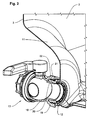
- the connecting flange 21 is manufactured as an injection molded part from an electrically conductive plastic, for example polyethylene with carbon or nanoparticles ( FIG. 2 ).
- the removal fitting 13 is provided with an electrical ground through a grounding conductor 23, which connects the connection flange 21 of the fitting housing 18 with the trough-like bottom 24 of the metallic subframe 17 ( FIG. 3 ).
- FIGS. 5 to 9 show various ways of mounting the grounding conductor 23 formed as an electric cable 26 on the tongue 25 on the flange 30 of the connecting flange 21st
- FIG. 5 is the one end 26 a of the electrical grounding cable 26 with an attached thereto annular tongue 27 to the fastening tongue 25 of the in FIG. 4 screwed connection flange 21 shown.
- FIGS. 6a and 6b illustrate the clipping of the annular tongue 27 of the grounding cable 26 on a mushroom-shaped pin 28 of the fastening tongue 25 on the flange 30 of the connecting flange 21st
- the fastening tongue 25 of the connecting flange 21 is divided by a predetermined bending point 29 into two sections 25a, 25b, wherein the adjacent to the flange 30 of the connecting flange 21 section 25a has a mushroom-shaped pin 28 and the free portions 25b has a mounting hole 31.
- the adjacent to the flange 30 of the connecting flange 21 section 25a has a mushroom-shaped pin 28 and the free portions 25b has a mounting hole 31.
- FIGS. 8a and 8b illustrate another type of attachment, in which the annular tongue 27 at one end 26a of the grounding cable 26 placed on a smooth pin 32 on the tongue 25 on the flange 30 of the connecting flange 21 and the over the annular tongue 27 protruding pin end 32a melted and a rivet head 32b is deformed.
- the pin 33 has on the mounting tongue 25 of the connecting flange 21 has a bore 34 for a at the one end 26 a of the grounding cable 26 mounted connector 35th
- the other end 26b of the earthing cable 26 may have a ring tongue 27 attached to it on the metal floor 24 of the undercarriage 17 are screwed. Furthermore, there is the possibility of the grounding cable 26 according to the in the FIGS. 6a, 6b; 7a, 7b; 8a, 8b and 9 shown attachment types to the metal floor 24 of the undercarriage 17 to install.
- FIG. 11a and 11b illustrate the formation of the grounding conductor 23 as an electrically conductive strip member 36 made of plastic or metal.
- the one end 36 a of the strip element 36 can be welded or glued to the tongue 25 on the flange ring 30 of the connection flange 21 of the removal fitting 13. It is also possible to rivet the strip element 36 with the tongue 25 of the connecting flange 21, to screw or verclinchen.
- the strip element 36 is attached to the tongue 25 on the flange 30 of the connecting flange 21 with a lug 37 arranged at its end 36a.
- the removal fitting 13 is the part of the connecting flange 21, which comes into contact with the leaking liquid during emptying of the transport and storage container 1, made of a plastic with an electrically conductive additional material, while the remaining part of the connecting flange of pure plastic consists.
Landscapes
- Engineering & Computer Science (AREA)
- Mechanical Engineering (AREA)
- Packages (AREA)
- Details Of Rigid Or Semi-Rigid Containers (AREA)
- Valve Housings (AREA)
- Closures For Containers (AREA)
- Loading And Unloading Of Fuel Tanks Or Ships (AREA)
- Check Valves (AREA)
Abstract
Description
- Die Erfindung betrifft eine Entnahmearmatur mit einem Armaturengehäuse aus Kunststoff, insbesondere Klappen- oder Kugelhahn, für Transport- und Lagerbehälter für Flüssigkeiten, die mit einem Innenbehälter aus Kunststoff mit einem verschließbaren Einfüllstutzen und einem Entleerstutzen zum Anschluss der Entnahmearmatur, einem Außenmantel aus Metallgitter oder Blech sowie einem palettenartigen Untergestell aus Metall oder einem zumindest teilweise elektrisch leitenden Kunststoff zum Abstützen des Innenbehälters ausgestattet sind.
- Bei einem in der
DE 198 15 082 A1 beschriebenen Transport- und Lagerbehälter für Flüssigkeiten ist in der am Auslaufstutzen des Innenbehälters angebrachten Entnahmearmatur der gattungsgemäßen Art ein Erdungsteil angeordnet, das als ein gekrümmtes Blech oder Plättchen aus Metall ausgebildet ist, das sich über einen Teilbereich der Innenbohrung der Entnahmearmatur erstreckt und über eine Befestigungsschraube und ein Erdungskabel an das Untergestell des Behälters angeschlossen ist. - Durch die zur Anbringung des Blechs oder Plättchens aus Metall in dem Armaturengehäuse aus Kunststoff erforderliche Befestigungsschraube, die durch die Gehäusewand geschraubt wird, ist die Dichtheit der Armatur nicht gewährleistet. Bei Transport- und Lagerbehältern für bestimmte flüssige Lebensmittel ist die Verwendung von Metallteilen nicht zulässig und damit mit dieser Armatur ausgerüstete Behälter für derartige flüssige Lebensmittel nicht verwendbar. Schließlich besteht bei dem bekannten Flüssigkeitsbehälter die Gefahr, dass beim Transport und der Lagerung von aggressiven Flüssigkeiten das Erdungsteil von der Flüssigkeit derart beschädigt wird, dass die elektrische Erdung nicht mehr funktionstüchtig ist.
- Ferner sind für Flüssigkeitsbehälter bestimmte Entnahmearmaturen mit einem antistatisch ausgerüsteten Gehäuse bekannt, die für ein Massenprodukt zu teuer sind.
- Der Erfindung liegt die Aufgabe zugrunde, die gattungsgemäße Entnahmearmatur für Transport- und Lagerbehälter für Flüssigkeiten im Hinblick auf eine sichere und umfassende Erdung zur Ableitung der sich beim Befüllen mit Flüssigkeiten und bei der Entnahme von Flüssigkeiten aufgrund von Flüssigkeitsreibung bildenden elektrischen Ladungen und eine preisgünstige Herstellung weiterzuentwickeln.
- Die Aufgabe wird erfindungsgemäß gelöst durch eine Entnahmearmatur für Transport- und Lagerbehälter für Flüssigkeiten mit den Merkmalen des Patentanspruchs 1.
- Die Unteransprüche beinhalten vorteilhafte und zweckmäßige Weiterbildungen der Erfindung.
- Die erfindungsgemäße Entnahmearmatur, deren Gehäuse mit einem Anschlussflansch aus elektrisch leitendem Kunststoff zum Anschweißen des Gehäuses an den Entleerstutzen des Kunststoffinnenbehälters eines mit einem Außenmantel aus Metallgitter oder Blech und mit einem palettenartigen Untergestell aus elektrisch leitendem Material ausgestatteten Transport- und Lagerbehälters für Flüssigkeiten ausgestattet ist, ermöglicht eine sichere elektrische Erdung der bei der Entleerung aus dem Innenbehälter auslaufenden Flüssigkeit über einen elektrischen Erdungsleiter, der den Anschlussflansch mit dem palettenartigen Untergestell oder dem Außenmantel verbindet. Die Entnahmearmatur mit dem Anschlussflansch aus elektrisch leitendem Kunststoff ist wesentlich preisgünstiger als die Entnahmearmatur nach dem Stand der Technik, deren gesamtes Kunststoffgehäuse antistatisch ausgerüstet ist.
- Die Erfindung ist nachstehend anhand von Zeichnungsfiguren erläutert, die folgendes darstellen:
- Fig. 1
- eine perspektivische Darstellung eines Transport- und Lagerbehälters für Flüssigkeiten,
- Fig. 2
- eine perspektivische teilweise aufgebrochene vergrößerte Darstellung der mit einem Anschlussflansch an dem Entleerstutzen des Innenbehälters des Transport- und Lagerbehälters angeschweißten Entnahmearmatur,
- Fig. 3
- eine vergrößerte perspektivische Darstellung des Auslaufbereichs des Transport- und Lagerbehälters mit der Entnahmearmatur,
- Fig. 4
- eine vergrößerte perspektivische Darstellung des Anschlussflansches der Entnahmearmatur,
- die Fign. 5, 6a, 6b, 7a, 7b, 8a, 8b und 9
- verschiedene Arten der Befestigung eines elektrischen Erdungskabels an einer Zunge des Anschlussflansches,
- Fig. 10
- eine Befestigungsmöglichkeit des Erdungskabels an der Bodenwanne des palettenartigen Untergestells des Transport- und Lagerbehälters und
- die Fign. 11a und 11b
- zwei Möglichkeiten zur Befestigung eines elektrischen Erdungsstreifenelements an dem Anschlussflansch der Entnahmearmatur.
- Der als Einweg- und Mehrwegbehälter einsetzbare Transport- und Lagerbehälter 1 für Flüssigkeiten nach
Figur 1 weist als Hauptbauteile einen austauschbaren quaderförmigen Innenbehälter 2 aus Kunststoff auf mit einer Stirnwand 3, einer Rückwand 4 und zwei Seitenwänden 5, 6, einem unteren als Ablaufboden ausgebildeten Boden 7 und einem oberen Boden 8, einem an diesem angeformten, mit einem Deckel 10 verschließbaren Einfüllstutzen 9 und einem an einer Einwölbung 11 im unteren Abschnitt der Stirnwand 3 des Innenbehälters 2 angeformten Entleerstutzen 12, der mit dem Innenbehälter 2 einteilig durch Blasformen hergestellt ist, zur Anbringung einer Entnahmearmatur 13, insbesondere eines Kugel- oder Klappenhahns, ferner einen als Gittermantel ausgebildeten Außenmantel 14 mit sich kreuzenden horizontalen und vertikalen Gitterstäben 15, 16 aus Metall zur Aufnahme des Innenbehälters 2 sowie ein palettenartiges Untergestell 17 mit euronormgerechten Längen- und Breitenabmessungen zur Abstützung des Innenbehälters 2. - Das aus einem Polyethylen hoher Dichte (PE-HD) spritzgegossene Armaturengehäuse 18 der Entnahmearmatur 13 ist mit dem mit einem Innengewinde 19 versehenen Einlaufstutzen 20 auf einen ein entsprechendes Außengewinde 22 aufweisenden Anschlussflansch 21 aufgeschraubt und gegen diesen abgedichtet und der Anschlussflansch 21 ist zusammen mit der aufgeschraubten Entnahmearmatur 13 vorzugsweise durch Spiegelschweißen an dem Entleerstutzen 12 des Innenbehälters 2 angebracht. Der Anschlussflansch 21 ist als Spritzgussteil aus einem elektrisch leitenden Kunststoff, zum Beispiel Polyethylen mit Kohlenstoff oder Nanopartikeln gefertigt (
Figur 2 ). - Die Entnahmearmatur 13 ist mit einer elektrischen Erdung durch einen Erdungsleiter 23 ausgestattet, der den Anschlussflansch 21 des Armaturengehäuses 18 mit dem wannenartigen Boden 24 des metallischen Untergestells 17 verbindet (
Figur 3 ). - Zum Befestigen des Erdungsleiters 23 an dem Flanschring 30 des Anschlussflansches 21 dient eine an dem Flanschring angespritzte Zunge 25, die im montierten Zustand der Entnahmearmatur 13 frei zugängig ist (
Figur 4 ). - Die
Figuren 5 bis 9 zeigen verschiedene Arten der Befestigung des als elektrisches Kabel 26 ausgebildeten Erdungsleiters 23 an der Zunge 25 am Flanschring 30 des Anschlussflansches 21. - Gemäß
Figur 5 wird das eine Ende 26a des elektrischen Erdungskabels 26 mit einer an diesem angebrachten Ringzunge 27 an die Befestigungszunge 25 des inFigur 4 dargestellten Anschlussflansches 21 angeschraubt. - Die
Figuren 6a und 6b verdeutlichen das Aufclipsen der Ringzunge 27 des Erdungskabels 26 auf einem pilzförmigen Zapfen 28 der Befestigungszunge 25 am Flanschring 30 des Anschlussflansches 21. - Bei der in den
Figuren 7a und 7b dargestellten Befestigungsart ist die Befestigungszunge 25 des Anschlussflansches 21 durch eine Sollbiegestelle 29 in zwei Abschnitte 25a, 25b unterteilt, wobei der an den Flanschring 30 des Anschlussflansches 21 angrenzende Abschnitt 25a einen pilzförmigen Zapfen 28 und der freie Abschnitte 25b ein Befestigungsloch 31 aufweist. Zur Befestigung des einen Endes 26a des Erdungskabels 26 wird dessen Ringzunge 27 auf den Zapfen 28 an dem Abschnitt 25a der Zunge aufgesteckt und der freie Abschnitt 25b der Zunge 25 wird umgebogen und auf den Zapfen 28 aufgeclipst, so dass die Ringzunge 27 des Kabels 26 zwischen den beiden Zungenabschnitten 25a, 25b der Zunge 25 des Anschlussflansches 21 festgeklemmt wird. - Die
Figuren 8a und 8b veranschaulichen eine weitere Art der Befestigung, bei der die Ringzunge 27 am einen Ende 26a des Erdungskabels 26 auf einen glatten Zapfen 32 an der Zunge 25 am Flanschring 30 des Anschlussflansches 21 aufgesetzt und das über die Ringzunge 27 vorstehende Zapfenende 32a aufgeschmolzen und zu einem Nietkopf 32b verformt wird. - Bei der in
Figur 9 gezeigten Befestigungsmöglichkeit besitzt der Zapfen 33 an der Befestigungszunge 25 des Anschlussflansches 21 eine Bohrung 34 für einen an dem einen Ende 26a des Erdungskabels 26 angebrachten Stecker 35. - Gemäß
Figur 10 kann das andere Ende 26b des Erdungskabels 26 mit einer an diesem angebrachten Ringzunge 27 an dem Blechboden 24 des Untergestells 17 festgeschraubt werden. Ferner besteht die Möglichkeit das Erdungskabel 26 entsprechend den in denFiguren 6a, 6b; 7a, 7b; 8a, 8b und 9 dargestellten Befestigungsarten an dem Blechboden 24 des Untergestells 17 anzubringen. - Des Weiteren besteht die Möglichkeit, das Ende 26b des Erdungskabels 26 an dem als Gittermantel ausgebildeten Außenmantel 14 der Transport- und Lagerbehälter anzubringen.
- Die
Figuren 11a und 11b veranschaulichen die Ausbildung des Erdungsleiters 23 als ein elektrisch leitendes Streifenelement 36 aus Kunststoff oder Metall. EntsprechendFigur 11a kann das eine Ende 36a des Streifenelementes 36 an die Zunge 25 am Flanschring 30 des Anschlussflansches 21 der Entnahmearmatur 13 angeschweißt oder angeklebt werden. Ferner besteht die Möglichkeit, das Streifenelement 36 mit der Zunge 25 des Anschlussflansches 21 zu vernieten, zu verschrauben oder zu verclinchen. - Bei der in
Figur 11b gezeigten Befestigungsweise wird das Streifenelement 36 mit einer an dessen Ende 36a angeordneten Lasche 37 auf die Zunge 25 am Flanschring 30 des Anschlussflansches 21 aufgesteckt. - Bei einer weiteren Ausführungsform der Entnahmearmatur 13 ist der Teil des Anschlussflansches 21, der beim Entleeren des Transport- und Lagerbehälters 1 mit der auslaufenden Flüssigkeit in Kontakt kommt, aus einem Kunststoff mit einem elektrisch leitenden Zusatzmaterial hergestellt, während der übrige Teil des Anschlussflansches aus reinem Kunststoff besteht. Durch einen derartigen Anschlussflansch werden die Herstellungskosten der Entnahmearmatur des Transport- und Lagerbehälters verbilligt.
-
- 1
- Transport- und Lagerbehälter
- 2
- Innenbehälter
- 3
- Stirnwand von 2
- 4
- Rückwand von 2
- 5
- Seitenwand von 2
- 6
- Seitenwand von 2
- 7
- unterer Boden von 2
- 8
- oberer Boden von 2
- 9
- Einfüllstutzen an 8
- 10
- Deckel von 9
- 11
- Einwölbung in 3
- 12
- Entleerstutzen von 2
- 13
- Entnahmearmatur
- 14
- Außenmantel
- 15
- horizontaler Gitterstab
- 16
- vertikaler Gitterstab
- 17
- Untergestell
- 18
- Armaturengehäuse von 13
- 19
- Innengewinde von 20
- 20
- Einlaufstutzen von 18
- 21
- Anschlussflansch
- 22
- Außengewinde von 21
- 23
- Erdungsleiter
- 24
- Boden von 17
- 25
- Zunge an 30 von 21
- 25a
- Abschnitt von 25
- 25b
- Abschnitt von 25
- 26
- elektrisches Kabel
- 26a
- Ende von 26
- 26b
- Ende von 26
- 27
- Ringzunge von 26
- 28
- Zapfen an 25
- 29
- Sollbiegestelle von 25
- 30
- Flanschring von 21
- 31
- Befestigungsloch in 25b
- 32
- Zapfen an 25 (
Figur 8a ) - 32a
- Zapfenende von 32
- 32b
- Nietkopf (
Figur 8b ) - 33
- Zapfen an 25 (
Figur 9 ) - 34
- Bohrung in 33
- 35
- Stecker an 26
- 36
- Streifenelement
- 36a
- Ende von 36
- 37
- Lasche an 36a
Claims (7)
- Entnahmearmatur mit einem Armaturengehäuse aus Kunststoff, insbesondere Klappen- oder Kugelhahn für Transport- und Lagerbehälter für Flüssigkeiten, die mit einem Innenbehälter aus Kunststoff mit einem verschließbaren Einfüllstutzen und einem Entleerstutzen zum Anschluss der Entnahmearmatur, einem Außenmantel aus Metallgitter oder Blech sowie einem palettenartigen Untergestell aus Metall oder einem zumindest teilweise elektrisch leitenden Kunststoff zum Abstützen des Innenbehälters ausgestattet sind, gekennzeichnet durch einen vollständig oder teilweise aus elektrisch leitfähigem Kunststoffmaterial hergestellten, als Gewindeflansch ausgebildeten Anschlussflansch (21), auf den das Armaturengehäuse (18) mit dem Einlaufstutzen (20) aufgeschraubt und mit dem das Armaturengehäuse (18) an den Entleerstutzen (12) des Innenbehälters (2) angeschweißt wird, sowie eine elektrische Erdung der Entnahmearmatur (13) durch einen Erdungsleiter (23), der den Anschlussflansch (21) des Armaturengehäuses (18) mit dem Untergestell (17) oder dem Außenmantel (14) des Transport- und Lagerbehälter (1) verbindet.
- Entnahmearmatur nach Anspruch 1, dadurch gekennzeichnet, dass der Anschlussflansch (21) als Kunststoff-Spritzgussteil hergestellt ist und an den Anschlussflansch (21) eine Zunge (25) zum Befestigen des Erdungsleiters (23) angespritzt ist, wobei die Zunge (25) im montierten Zustand der Entnahmearmatur (13) frei zugängig ist.
- Entnahmearmatur nach Anspruch 1 und 2, dadurch gekennzeichnet, dass der Erdungsleiter (23) als elektrisches Kabel (26) ausgebildet ist.
- Entnahmearmatur nach Anspruch 1 und 2, gekennzeichnet durch eine Ausbildung des Erdungsleiters (23) als ein elektrisch leitendes Streifenelement (36) aus Kunststoff oder Metall.
- Entnahmearmatur nach einem der Ansprüche 1 bis 4, dadurch gekennzeichnet, dass der Teil des Anschlussflansches (21), der beim Entleeren des Transport- und Lagerbehälters (1) mit der auslaufenden Flüssigkeit in Kontakt kommt, aus einem Kunststoff mit elektrisch leitendem Zusatzmaterial hergestellt ist, während der übrige Teil des Anschlussflansches aus reinem Kunststoff besteht.
- Entnahmearmatur nach einem der Ansprüche 1 bis 5, dadurch gekennzeichnet, dass der Anschlussflansch (21) aus Polyethylen mit Kohlenstoff hergestellt ist.
- Entnahmearmatur nach einem der Ansprüche 1 bis 5, dadurch gekennzeichnet, dass der Anschlussflansch (21) aus Polyethylen mit Nanopartikeln besteht.
Applications Claiming Priority (1)
| Application Number | Priority Date | Filing Date | Title |
|---|---|---|---|
| DE102008038546A DE102008038546A1 (de) | 2008-08-20 | 2008-08-20 | Entnahmearmatur mit einem Armaturengehäuse aus Kunststoff für Transport-und Lagerbehälter für Flüssigkeiten |
Publications (2)
| Publication Number | Publication Date |
|---|---|
| EP2157028A1 true EP2157028A1 (de) | 2010-02-24 |
| EP2157028B1 EP2157028B1 (de) | 2011-08-10 |
Family
ID=40934892
Family Applications (1)
| Application Number | Title | Priority Date | Filing Date |
|---|---|---|---|
| EP09008104A Active EP2157028B1 (de) | 2008-08-20 | 2009-06-20 | Entnahmearmatur mit einem Armaturengehäuse aus Kunststoff für Transport- und Lagerbehälter für Flüssigkeiten |
Country Status (15)
| Country | Link |
|---|---|
| US (1) | US10676266B2 (de) |
| EP (1) | EP2157028B1 (de) |
| JP (1) | JP4917633B2 (de) |
| CN (1) | CN101654178B (de) |
| AR (1) | AR072548A1 (de) |
| AT (1) | ATE519688T1 (de) |
| AU (1) | AU2009208089B2 (de) |
| BR (1) | BRPI0903193B1 (de) |
| DE (1) | DE102008038546A1 (de) |
| ES (1) | ES2371309T3 (de) |
| MX (1) | MX2009008379A (de) |
| MY (1) | MY149343A (de) |
| RU (1) | RU2401236C1 (de) |
| SA (1) | SA109300521B1 (de) |
| ZA (1) | ZA200904869B (de) |
Cited By (1)
| Publication number | Priority date | Publication date | Assignee | Title |
|---|---|---|---|---|
| EP2239206A3 (de) * | 2009-04-04 | 2011-02-23 | Protechna S.A. | Entnahmearmatur mit einem Armaturengehäuse aus Kunststoff für Transport- und Lagerbehälter für Flüssigkeiten und Verfahren zur Herstellung des elektrisch geerdeten Anschlussflansches zur Befestigung der Entnahmearmatur an dem Entleerstutzen des Innenbehälters des Transport- und Lagerbehälters |
Families Citing this family (5)
| Publication number | Priority date | Publication date | Assignee | Title |
|---|---|---|---|---|
| DE102010039328A1 (de) * | 2010-08-13 | 2012-02-16 | Protechna S.A. | Entnahmearmatur für einen Transport- und Lagerbehälter für Flüssigkeiten sowie Transport- und Lagerbehälter mit einer solchen Entnahmearmatur |
| DE102012022129B4 (de) * | 2012-11-13 | 2024-10-10 | Kautex Textron Gmbh & Co. Kg | Elektrisch Leitfähiges Mundstück |
| DE102018108755B3 (de) * | 2018-04-12 | 2019-08-14 | Protechna S.A. | Sicherungseinrichtung für eine Entnahmearmatur |
| CN112141531B (zh) * | 2020-09-14 | 2025-05-30 | 中国国际海运集装箱(集团)股份有限公司 | 一种托盘箱 |
| CN113247481A (zh) * | 2021-06-15 | 2021-08-13 | 上海箱箱智能科技有限公司 | 中型散装容器 |
Citations (4)
| Publication number | Priority date | Publication date | Assignee | Title |
|---|---|---|---|---|
| DE19815082A1 (de) | 1998-04-06 | 1999-10-14 | Protechna Sa | Transport- und Lagerbehälter für Flüssigkeiten |
| DE10242954A1 (de) * | 2002-09-17 | 2004-03-25 | Protechna S.A. | Transport- und Lagerbehälter für Flüssigkeiten |
| EP1462386A1 (de) * | 2003-03-26 | 2004-09-29 | Protechna S.A. | Transport- und Lagerbehälter für Flüssigkeiten |
| WO2005082739A1 (de) * | 2004-02-27 | 2005-09-09 | Mauser-Werke Gmbh & Co. Kg | Palettencontainer |
Family Cites Families (17)
| Publication number | Priority date | Publication date | Assignee | Title |
|---|---|---|---|---|
| JPS578789A (en) * | 1980-06-20 | 1982-01-18 | Dainippon Ink & Chem Inc | Preparation of coenzyme q10 by fermentation |
| JPS5946814A (ja) * | 1982-09-10 | 1984-03-16 | Toshiba Corp | 電磁流量計 |
| US4689271A (en) * | 1984-08-11 | 1987-08-25 | Bayer Aktiengesellschaft | Coating for metallic substrates |
| US5201493A (en) * | 1992-03-12 | 1993-04-13 | Kim Young M | Electrically insulated ball valve device |
| DE19720931C2 (de) * | 1997-05-20 | 1999-12-02 | Protechna Sa | Transport- und Lagerbehälter für Flüssigkeiten |
| DE19731518C2 (de) * | 1997-07-23 | 2002-02-07 | Protechna Sa | Transport- und Lagerbehälter für Flüssigkeiten |
| JP3895853B2 (ja) * | 1997-11-27 | 2007-03-22 | ゼオン化成株式会社 | コンテナ |
| DE19840080B4 (de) * | 1998-09-03 | 2004-01-29 | Basf Coatings Ag | Verfahren zum Einbringen eines Behälters aus elektrisch nicht leitendem Material in explosionsgefährdete Räume |
| DE10161416A1 (de) * | 2001-12-13 | 2003-06-18 | Roth Werke Gmbh | Behälter, insbesondere Paletteninnenbehälter |
| ATE275073T1 (de) * | 2002-03-14 | 2004-09-15 | Fustiplast Spa | Antistatischer behälter |
| DE10216960B4 (de) * | 2002-04-17 | 2005-07-21 | Schneider, Ekkehard, Dipl.-Ing. | Gegen elektrostatische Aufladung geschützte Behälteranordnung für fliessfähige Stoffe |
| ZA200306098B (en) * | 2002-08-13 | 2003-10-15 | Protechna Sa | Withdrawal valve of plastics material for transportation and storage container for liquids. |
| US6841883B1 (en) * | 2003-03-31 | 2005-01-11 | Micron Technology, Inc. | Multi-dice chip scale semiconductor components and wafer level methods of fabrication |
| DE102004013224B4 (de) * | 2004-03-18 | 2005-12-15 | Schütz GmbH & Co. KGaA | Verfahren zur Herstellung von Kunststoffbehältern für Flüssigkeiten |
| DE202006001222U1 (de) * | 2006-01-24 | 2007-05-31 | Mauser-Werke Gmbh | Palette |
| DE102006020447B4 (de) * | 2006-05-03 | 2008-01-31 | Sotralentz Packaging S.A.S. | Absperrorgan für einen Behälter, insbesondere Palettenbehälter |
| EP2008946B1 (de) * | 2007-06-28 | 2010-06-02 | Daviplast - Servicos de Consultoria, Sociedade Unipessoal LDA. | Behälter für Flüssigkeiten |
-
2008
- 2008-08-20 DE DE102008038546A patent/DE102008038546A1/de not_active Withdrawn
-
2009
- 2009-06-17 RU RU2009123166/12A patent/RU2401236C1/ru active
- 2009-06-20 AT AT09008104T patent/ATE519688T1/de active
- 2009-06-20 ES ES09008104T patent/ES2371309T3/es active Active
- 2009-06-20 EP EP09008104A patent/EP2157028B1/de active Active
- 2009-07-03 AR ARP090102494A patent/AR072548A1/es active IP Right Grant
- 2009-07-09 JP JP2009162820A patent/JP4917633B2/ja active Active
- 2009-07-13 ZA ZA200904869A patent/ZA200904869B/en unknown
- 2009-07-24 US US12/460,894 patent/US10676266B2/en active Active
- 2009-07-30 CN CN2009101618284A patent/CN101654178B/zh active Active
- 2009-08-06 MX MX2009008379A patent/MX2009008379A/es active IP Right Grant
- 2009-08-10 AU AU2009208089A patent/AU2009208089B2/en active Active
- 2009-08-14 MY MYPI20093388A patent/MY149343A/en unknown
- 2009-08-15 SA SA109300521A patent/SA109300521B1/ar unknown
- 2009-08-18 BR BRPI0903193-6A patent/BRPI0903193B1/pt active IP Right Grant
Patent Citations (4)
| Publication number | Priority date | Publication date | Assignee | Title |
|---|---|---|---|---|
| DE19815082A1 (de) | 1998-04-06 | 1999-10-14 | Protechna Sa | Transport- und Lagerbehälter für Flüssigkeiten |
| DE10242954A1 (de) * | 2002-09-17 | 2004-03-25 | Protechna S.A. | Transport- und Lagerbehälter für Flüssigkeiten |
| EP1462386A1 (de) * | 2003-03-26 | 2004-09-29 | Protechna S.A. | Transport- und Lagerbehälter für Flüssigkeiten |
| WO2005082739A1 (de) * | 2004-02-27 | 2005-09-09 | Mauser-Werke Gmbh & Co. Kg | Palettencontainer |
Cited By (3)
| Publication number | Priority date | Publication date | Assignee | Title |
|---|---|---|---|---|
| EP2239206A3 (de) * | 2009-04-04 | 2011-02-23 | Protechna S.A. | Entnahmearmatur mit einem Armaturengehäuse aus Kunststoff für Transport- und Lagerbehälter für Flüssigkeiten und Verfahren zur Herstellung des elektrisch geerdeten Anschlussflansches zur Befestigung der Entnahmearmatur an dem Entleerstutzen des Innenbehälters des Transport- und Lagerbehälters |
| EP2388207A1 (de) * | 2009-04-04 | 2011-11-23 | Protechna S.A. | Entnahmearmatur mit einem Armaturengehäuse aus Kunststoff für Transport- und Lagerbehälter für Flüssigkeiten |
| US8477471B2 (en) | 2009-04-04 | 2013-07-02 | Protechna S.A. | Tapping armature for a transport and storage container for liquids |
Also Published As
| Publication number | Publication date |
|---|---|
| DE102008038546A1 (de) | 2010-03-04 |
| AU2009208089A1 (en) | 2010-03-11 |
| BRPI0903193A2 (pt) | 2010-05-25 |
| ES2371309T3 (es) | 2011-12-29 |
| JP4917633B2 (ja) | 2012-04-18 |
| RU2401236C1 (ru) | 2010-10-10 |
| ZA200904869B (en) | 2010-04-28 |
| JP2010047318A (ja) | 2010-03-04 |
| MY149343A (en) | 2013-08-30 |
| MX2009008379A (es) | 2010-03-22 |
| AU2009208089B2 (en) | 2012-04-19 |
| BRPI0903193B1 (pt) | 2019-02-19 |
| CN101654178B (zh) | 2011-08-17 |
| EP2157028B1 (de) | 2011-08-10 |
| SA109300521B1 (ar) | 2014-05-01 |
| US20100044612A1 (en) | 2010-02-25 |
| CN101654178A (zh) | 2010-02-24 |
| US10676266B2 (en) | 2020-06-09 |
| AR072548A1 (es) | 2010-09-08 |
| ATE519688T1 (de) | 2011-08-15 |
Similar Documents
| Publication | Publication Date | Title |
|---|---|---|
| EP2239206B1 (de) | Entnahmearmatur mit einem Armaturengehäuse aus Kunststoff für Transport- und Lagerbehälter für Flüssigkeiten und Verfahren zur Herstellung des elektrisch geerdeten Anschlussflansches zur Befestigung der Entnahmearmatur an dem Entleerstutzen des Innenbehälters des Transport- und Lagerbehälters | |
| EP2157028B1 (de) | Entnahmearmatur mit einem Armaturengehäuse aus Kunststoff für Transport- und Lagerbehälter für Flüssigkeiten | |
| DE4341646A1 (de) | Gewindestutzen an Öffnungen von Flüssigkeitsbehältern aus Blech | |
| EP2090528B1 (de) | Transport- und Lagerbehälter für Flüssigkeiten | |
| EP2418168B1 (de) | Entnahmearmatur für einen Transport- und Lagerbehälter für Flüssigkeiten sowie Transport- und Lagerbehälter mit einer solchen Entnahmearmatur | |
| WO2008142016A1 (de) | Elektrische anschlusseinrichtung für photovoltaische module | |
| EP1422161B1 (de) | Transport- und Lagerbehälter für Flüssigkeiten | |
| EP3400181A1 (de) | Palettencontainer | |
| DE3002651C2 (de) | ||
| WO2015078460A1 (de) | Elektronische baugruppe mit einem gehäuse aus einem kunststoffteil und einem metallteil | |
| DE102017106551A1 (de) | Fahrzeugsitzlehnenwandstruktur | |
| EP2288245A2 (de) | Gehäuse für eine elektrische Einrichtung | |
| EP1345789A1 (de) | Vorrichtung zum fördern von kraftstoff aus einem vorratsbehälter zu einer brennkraftmaschine | |
| EP2652307B1 (de) | Kraftstoff-fördereinheit | |
| DE112007000951T5 (de) | Aufnahmegehäuse | |
| EP2465403A2 (de) | Geschirrspülmaschine | |
| EP2863041B1 (de) | Tank | |
| DE19530526A1 (de) | Kraftstoffilter mit einem elektrisch leitfähigen Gehäuse für insbesondere Kraftfahrzeuge | |
| EP1319608B1 (de) | Behälter, insbesondere Paletteninnenbehälter | |
| EP1969683B1 (de) | Steckverbindungsanordnung | |
| DE102012013880A1 (de) | Kraftstofftank | |
| DE102011006853A1 (de) | Gehäuse für ein Umsetzgetriebe eines Scheibenwischers | |
| DE102015207712A1 (de) | Fördermodul mit integriertem Widerstand | |
| DE19906563A1 (de) | Elektrokabel | |
| DE102007020886A1 (de) | Palettenbehälter zum Transport und zur Lagerung von flüssigen, pastösen, granulat- und pulverförmigen Füllgütern |
Legal Events
| Date | Code | Title | Description |
|---|---|---|---|
| PUAI | Public reference made under article 153(3) epc to a published international application that has entered the european phase |
Free format text: ORIGINAL CODE: 0009012 |
|
| 17P | Request for examination filed |
Effective date: 20090716 |
|
| AK | Designated contracting states |
Kind code of ref document: A1 Designated state(s): AT BE BG CH CY CZ DE DK EE ES FI FR GB GR HR HU IE IS IT LI LT LU LV MC MK MT NL NO PL PT RO SE SI SK TR |
|
| AX | Request for extension of the european patent |
Extension state: AL BA RS |
|
| 17Q | First examination report despatched |
Effective date: 20100507 |
|
| GRAP | Despatch of communication of intention to grant a patent |
Free format text: ORIGINAL CODE: EPIDOSNIGR1 |
|
| GRAS | Grant fee paid |
Free format text: ORIGINAL CODE: EPIDOSNIGR3 |
|
| GRAA | (expected) grant |
Free format text: ORIGINAL CODE: 0009210 |
|
| AK | Designated contracting states |
Kind code of ref document: B1 Designated state(s): AT BE BG CH CY CZ DE DK EE ES FI FR GB GR HR HU IE IS IT LI LT LU LV MC MK MT NL NO PL PT RO SE SI SK TR |
|
| REG | Reference to a national code |
Ref country code: GB Ref legal event code: FG4D Free format text: NOT ENGLISH |
|
| REG | Reference to a national code |
Ref country code: CH Ref legal event code: EP |
|
| REG | Reference to a national code |
Ref country code: IE Ref legal event code: FG4D Free format text: LANGUAGE OF EP DOCUMENT: GERMAN |
|
| REG | Reference to a national code |
Ref country code: DE Ref legal event code: R096 Ref document number: 502009001071 Country of ref document: DE Effective date: 20111013 |
|
| REG | Reference to a national code |
Ref country code: SE Ref legal event code: TRGR |
|
| REG | Reference to a national code |
Ref country code: NL Ref legal event code: VDEP Effective date: 20110810 |
|
| REG | Reference to a national code |
Ref country code: ES Ref legal event code: FG2A Ref document number: 2371309 Country of ref document: ES Kind code of ref document: T3 Effective date: 20111229 |
|
| LTIE | Lt: invalidation of european patent or patent extension |
Effective date: 20110810 |
|
| PG25 | Lapsed in a contracting state [announced via postgrant information from national office to epo] |
Ref country code: NO Free format text: LAPSE BECAUSE OF FAILURE TO SUBMIT A TRANSLATION OF THE DESCRIPTION OR TO PAY THE FEE WITHIN THE PRESCRIBED TIME-LIMIT Effective date: 20111110 Ref country code: LT Free format text: LAPSE BECAUSE OF FAILURE TO SUBMIT A TRANSLATION OF THE DESCRIPTION OR TO PAY THE FEE WITHIN THE PRESCRIBED TIME-LIMIT Effective date: 20110810 Ref country code: IS Free format text: LAPSE BECAUSE OF FAILURE TO SUBMIT A TRANSLATION OF THE DESCRIPTION OR TO PAY THE FEE WITHIN THE PRESCRIBED TIME-LIMIT Effective date: 20111210 Ref country code: HR Free format text: LAPSE BECAUSE OF FAILURE TO SUBMIT A TRANSLATION OF THE DESCRIPTION OR TO PAY THE FEE WITHIN THE PRESCRIBED TIME-LIMIT Effective date: 20110810 Ref country code: PT Free format text: LAPSE BECAUSE OF FAILURE TO SUBMIT A TRANSLATION OF THE DESCRIPTION OR TO PAY THE FEE WITHIN THE PRESCRIBED TIME-LIMIT Effective date: 20111212 Ref country code: NL Free format text: LAPSE BECAUSE OF FAILURE TO SUBMIT A TRANSLATION OF THE DESCRIPTION OR TO PAY THE FEE WITHIN THE PRESCRIBED TIME-LIMIT Effective date: 20110810 Ref country code: FI Free format text: LAPSE BECAUSE OF FAILURE TO SUBMIT A TRANSLATION OF THE DESCRIPTION OR TO PAY THE FEE WITHIN THE PRESCRIBED TIME-LIMIT Effective date: 20110810 |
|
| PG25 | Lapsed in a contracting state [announced via postgrant information from national office to epo] |
Ref country code: PL Free format text: LAPSE BECAUSE OF FAILURE TO SUBMIT A TRANSLATION OF THE DESCRIPTION OR TO PAY THE FEE WITHIN THE PRESCRIBED TIME-LIMIT Effective date: 20110810 Ref country code: CY Free format text: LAPSE BECAUSE OF FAILURE TO SUBMIT A TRANSLATION OF THE DESCRIPTION OR TO PAY THE FEE WITHIN THE PRESCRIBED TIME-LIMIT Effective date: 20110810 Ref country code: SI Free format text: LAPSE BECAUSE OF FAILURE TO SUBMIT A TRANSLATION OF THE DESCRIPTION OR TO PAY THE FEE WITHIN THE PRESCRIBED TIME-LIMIT Effective date: 20110810 Ref country code: LV Free format text: LAPSE BECAUSE OF FAILURE TO SUBMIT A TRANSLATION OF THE DESCRIPTION OR TO PAY THE FEE WITHIN THE PRESCRIBED TIME-LIMIT Effective date: 20110810 |
|
| REG | Reference to a national code |
Ref country code: IE Ref legal event code: FD4D |
|
| PG25 | Lapsed in a contracting state [announced via postgrant information from national office to epo] |
Ref country code: CZ Free format text: LAPSE BECAUSE OF FAILURE TO SUBMIT A TRANSLATION OF THE DESCRIPTION OR TO PAY THE FEE WITHIN THE PRESCRIBED TIME-LIMIT Effective date: 20110810 Ref country code: IE Free format text: LAPSE BECAUSE OF FAILURE TO SUBMIT A TRANSLATION OF THE DESCRIPTION OR TO PAY THE FEE WITHIN THE PRESCRIBED TIME-LIMIT Effective date: 20110810 Ref country code: SK Free format text: LAPSE BECAUSE OF FAILURE TO SUBMIT A TRANSLATION OF THE DESCRIPTION OR TO PAY THE FEE WITHIN THE PRESCRIBED TIME-LIMIT Effective date: 20110810 |
|
| PG25 | Lapsed in a contracting state [announced via postgrant information from national office to epo] |
Ref country code: RO Free format text: LAPSE BECAUSE OF FAILURE TO SUBMIT A TRANSLATION OF THE DESCRIPTION OR TO PAY THE FEE WITHIN THE PRESCRIBED TIME-LIMIT Effective date: 20110810 Ref country code: EE Free format text: LAPSE BECAUSE OF FAILURE TO SUBMIT A TRANSLATION OF THE DESCRIPTION OR TO PAY THE FEE WITHIN THE PRESCRIBED TIME-LIMIT Effective date: 20110810 |
|
| PLBE | No opposition filed within time limit |
Free format text: ORIGINAL CODE: 0009261 |
|
| STAA | Information on the status of an ep patent application or granted ep patent |
Free format text: STATUS: NO OPPOSITION FILED WITHIN TIME LIMIT |
|
| PG25 | Lapsed in a contracting state [announced via postgrant information from national office to epo] |
Ref country code: DK Free format text: LAPSE BECAUSE OF FAILURE TO SUBMIT A TRANSLATION OF THE DESCRIPTION OR TO PAY THE FEE WITHIN THE PRESCRIBED TIME-LIMIT Effective date: 20110810 |
|
| 26N | No opposition filed |
Effective date: 20120511 |
|
| REG | Reference to a national code |
Ref country code: DE Ref legal event code: R097 Ref document number: 502009001071 Country of ref document: DE Effective date: 20120511 |
|
| BERE | Be: lapsed |
Owner name: PROTECHNA S.A. Effective date: 20120630 |
|
| PG25 | Lapsed in a contracting state [announced via postgrant information from national office to epo] |
Ref country code: MC Free format text: LAPSE BECAUSE OF NON-PAYMENT OF DUE FEES Effective date: 20120630 |
|
| PG25 | Lapsed in a contracting state [announced via postgrant information from national office to epo] |
Ref country code: MK Free format text: LAPSE BECAUSE OF FAILURE TO SUBMIT A TRANSLATION OF THE DESCRIPTION OR TO PAY THE FEE WITHIN THE PRESCRIBED TIME-LIMIT Effective date: 20110810 |
|
| PG25 | Lapsed in a contracting state [announced via postgrant information from national office to epo] |
Ref country code: BE Free format text: LAPSE BECAUSE OF NON-PAYMENT OF DUE FEES Effective date: 20120630 |
|
| PG25 | Lapsed in a contracting state [announced via postgrant information from national office to epo] |
Ref country code: BG Free format text: LAPSE BECAUSE OF FAILURE TO SUBMIT A TRANSLATION OF THE DESCRIPTION OR TO PAY THE FEE WITHIN THE PRESCRIBED TIME-LIMIT Effective date: 20111110 |
|
| PG25 | Lapsed in a contracting state [announced via postgrant information from national office to epo] |
Ref country code: MT Free format text: LAPSE BECAUSE OF FAILURE TO SUBMIT A TRANSLATION OF THE DESCRIPTION OR TO PAY THE FEE WITHIN THE PRESCRIBED TIME-LIMIT Effective date: 20110810 |
|
| PG25 | Lapsed in a contracting state [announced via postgrant information from national office to epo] |
Ref country code: LU Free format text: LAPSE BECAUSE OF NON-PAYMENT OF DUE FEES Effective date: 20120620 |
|
| PG25 | Lapsed in a contracting state [announced via postgrant information from national office to epo] |
Ref country code: HU Free format text: LAPSE BECAUSE OF FAILURE TO SUBMIT A TRANSLATION OF THE DESCRIPTION OR TO PAY THE FEE WITHIN THE PRESCRIBED TIME-LIMIT Effective date: 20090620 |
|
| PG25 | Lapsed in a contracting state [announced via postgrant information from national office to epo] |
Ref country code: GR Free format text: LAPSE BECAUSE OF FAILURE TO SUBMIT A TRANSLATION OF THE DESCRIPTION OR TO PAY THE FEE WITHIN THE PRESCRIBED TIME-LIMIT Effective date: 20110810 |
|
| REG | Reference to a national code |
Ref country code: AT Ref legal event code: MM01 Ref document number: 519688 Country of ref document: AT Kind code of ref document: T Effective date: 20140620 |
|
| PG25 | Lapsed in a contracting state [announced via postgrant information from national office to epo] |
Ref country code: AT Free format text: LAPSE BECAUSE OF NON-PAYMENT OF DUE FEES Effective date: 20140620 |
|
| REG | Reference to a national code |
Ref country code: FR Ref legal event code: PLFP Year of fee payment: 8 |
|
| REG | Reference to a national code |
Ref country code: FR Ref legal event code: PLFP Year of fee payment: 9 |
|
| REG | Reference to a national code |
Ref country code: FR Ref legal event code: PLFP Year of fee payment: 10 |
|
| P01 | Opt-out of the competence of the unified patent court (upc) registered |
Effective date: 20230526 |
|
| PGFP | Annual fee paid to national office [announced via postgrant information from national office to epo] |
Ref country code: GB Payment date: 20250620 Year of fee payment: 17 |
|
| PGFP | Annual fee paid to national office [announced via postgrant information from national office to epo] |
Ref country code: FR Payment date: 20250626 Year of fee payment: 17 |
|
| PGFP | Annual fee paid to national office [announced via postgrant information from national office to epo] |
Ref country code: TR Payment date: 20250617 Year of fee payment: 17 |
|
| PGFP | Annual fee paid to national office [announced via postgrant information from national office to epo] |
Ref country code: SE Payment date: 20250618 Year of fee payment: 17 |
|
| PGFP | Annual fee paid to national office [announced via postgrant information from national office to epo] |
Ref country code: ES Payment date: 20250718 Year of fee payment: 17 |
|
| PGFP | Annual fee paid to national office [announced via postgrant information from national office to epo] |
Ref country code: DE Payment date: 20250811 Year of fee payment: 17 |
|
| PGFP | Annual fee paid to national office [announced via postgrant information from national office to epo] |
Ref country code: IT Payment date: 20250630 Year of fee payment: 17 |
|
| PGFP | Annual fee paid to national office [announced via postgrant information from national office to epo] |
Ref country code: CH Payment date: 20250911 Year of fee payment: 17 |