EP2158071B1 - Procede et dispositif de realisation d'une dalle en blochets de bois de bout - Google Patents
Procede et dispositif de realisation d'une dalle en blochets de bois de bout Download PDFInfo
- Publication number
- EP2158071B1 EP2158071B1 EP08805834.2A EP08805834A EP2158071B1 EP 2158071 B1 EP2158071 B1 EP 2158071B1 EP 08805834 A EP08805834 A EP 08805834A EP 2158071 B1 EP2158071 B1 EP 2158071B1
- Authority
- EP
- European Patent Office
- Prior art keywords
- blocks
- cutting
- station
- producing
- discs
- Prior art date
- Legal status (The legal status is an assumption and is not a legal conclusion. Google has not performed a legal analysis and makes no representation as to the accuracy of the status listed.)
- Not-in-force
Links
- 239000002023 wood Substances 0.000 title claims description 42
- 238000000034 method Methods 0.000 title claims description 13
- 238000005520 cutting process Methods 0.000 claims description 24
- 239000000853 adhesive Substances 0.000 claims description 10
- 230000001070 adhesive effect Effects 0.000 claims description 10
- 238000004519 manufacturing process Methods 0.000 claims description 6
- 239000004619 high density foam Substances 0.000 claims 1
- 238000003825 pressing Methods 0.000 claims 1
- 238000001035 drying Methods 0.000 description 8
- 239000006260 foam Substances 0.000 description 6
- 239000000835 fiber Substances 0.000 description 4
- 230000008901 benefit Effects 0.000 description 3
- XLYOFNOQVPJJNP-UHFFFAOYSA-N water Substances O XLYOFNOQVPJJNP-UHFFFAOYSA-N 0.000 description 3
- 241000269907 Pleuronectes platessa Species 0.000 description 2
- 239000011248 coating agent Substances 0.000 description 2
- 238000000576 coating method Methods 0.000 description 2
- 238000013016 damping Methods 0.000 description 2
- 230000007547 defect Effects 0.000 description 2
- 238000009408 flooring Methods 0.000 description 2
- 239000000463 material Substances 0.000 description 2
- 230000005012 migration Effects 0.000 description 2
- 238000013508 migration Methods 0.000 description 2
- 238000005299 abrasion Methods 0.000 description 1
- 238000004026 adhesive bonding Methods 0.000 description 1
- 239000007795 chemical reaction product Substances 0.000 description 1
- 230000001627 detrimental effect Effects 0.000 description 1
- 238000006073 displacement reaction Methods 0.000 description 1
- 230000000694 effects Effects 0.000 description 1
- 239000000945 filler Substances 0.000 description 1
- 239000003292 glue Substances 0.000 description 1
- 238000009434 installation Methods 0.000 description 1
- 238000009413 insulation Methods 0.000 description 1
- 238000013021 overheating Methods 0.000 description 1
- 230000000717 retained effect Effects 0.000 description 1
- 125000006850 spacer group Chemical group 0.000 description 1
- 241000894007 species Species 0.000 description 1
- 238000003860 storage Methods 0.000 description 1
- 230000008961 swelling Effects 0.000 description 1
Images

Classifications
-
- B—PERFORMING OPERATIONS; TRANSPORTING
- B27—WORKING OR PRESERVING WOOD OR SIMILAR MATERIAL; NAILING OR STAPLING MACHINES IN GENERAL
- B27M—WORKING OF WOOD NOT PROVIDED FOR IN SUBCLASSES B27B - B27L; MANUFACTURE OF SPECIFIC WOODEN ARTICLES
- B27M3/00—Manufacture or reconditioning of specific semi-finished or finished articles
- B27M3/04—Manufacture or reconditioning of specific semi-finished or finished articles of flooring elements, e.g. parqueting blocks
-
- B—PERFORMING OPERATIONS; TRANSPORTING
- B23—MACHINE TOOLS; METAL-WORKING NOT OTHERWISE PROVIDED FOR
- B23D—PLANING; SLOTTING; SHEARING; BROACHING; SAWING; FILING; SCRAPING; LIKE OPERATIONS FOR WORKING METAL BY REMOVING MATERIAL, NOT OTHERWISE PROVIDED FOR
- B23D45/00—Sawing machines or sawing devices with circular saw blades or with friction saw discs
- B23D45/10—Sawing machines or sawing devices with circular saw blades or with friction saw discs with a plurality of circular saw blades
-
- E—FIXED CONSTRUCTIONS
- E04—BUILDING
- E04F—FINISHING WORK ON BUILDINGS, e.g. STAIRS, FLOORS
- E04F15/00—Flooring
- E04F15/02—Flooring or floor layers composed of a number of similar elements
- E04F15/04—Flooring or floor layers composed of a number of similar elements only of wood or with a top layer of wood, e.g. with wooden or metal connecting members
- E04F15/047—Flooring or floor layers composed of a number of similar elements only of wood or with a top layer of wood, e.g. with wooden or metal connecting members with a butcher-block like top surface
-
- E—FIXED CONSTRUCTIONS
- E04—BUILDING
- E04F—FINISHING WORK ON BUILDINGS, e.g. STAIRS, FLOORS
- E04F15/00—Flooring
- E04F15/16—Flooring, e.g. parquet on flexible web, laid as flexible webs; Webs specially adapted for use as flooring; Parquet on flexible web
- E04F15/166—Flooring consisting of a number of elements carried by a common flexible web, e.g. rollable parquet
-
- E—FIXED CONSTRUCTIONS
- E04—BUILDING
- E04F—FINISHING WORK ON BUILDINGS, e.g. STAIRS, FLOORS
- E04F15/00—Flooring
- E04F15/18—Separately-laid insulating layers; Other additional insulating measures; Floating floors
- E04F15/20—Separately-laid insulating layers; Other additional insulating measures; Floating floors for sound insulation
- E04F15/203—Separately-laid layers for sound insulation
-
- Y—GENERAL TAGGING OF NEW TECHNOLOGICAL DEVELOPMENTS; GENERAL TAGGING OF CROSS-SECTIONAL TECHNOLOGIES SPANNING OVER SEVERAL SECTIONS OF THE IPC; TECHNICAL SUBJECTS COVERED BY FORMER USPC CROSS-REFERENCE ART COLLECTIONS [XRACs] AND DIGESTS
- Y10—TECHNICAL SUBJECTS COVERED BY FORMER USPC
- Y10T—TECHNICAL SUBJECTS COVERED BY FORMER US CLASSIFICATION
- Y10T156/00—Adhesive bonding and miscellaneous chemical manufacture
- Y10T156/10—Methods of surface bonding and/or assembly therefor
- Y10T156/1089—Methods of surface bonding and/or assembly therefor of discrete laminae to single face of additional lamina
- Y10T156/1092—All laminae planar and face to face
-
- Y—GENERAL TAGGING OF NEW TECHNOLOGICAL DEVELOPMENTS; GENERAL TAGGING OF CROSS-SECTIONAL TECHNOLOGIES SPANNING OVER SEVERAL SECTIONS OF THE IPC; TECHNICAL SUBJECTS COVERED BY FORMER USPC CROSS-REFERENCE ART COLLECTIONS [XRACs] AND DIGESTS
- Y10—TECHNICAL SUBJECTS COVERED BY FORMER USPC
- Y10T—TECHNICAL SUBJECTS COVERED BY FORMER US CLASSIFICATION
- Y10T156/00—Adhesive bonding and miscellaneous chemical manufacture
- Y10T156/12—Surface bonding means and/or assembly means with cutting, punching, piercing, severing or tearing
- Y10T156/13—Severing followed by associating with part from same source
Definitions
- the present invention relates to a method and a device for producing a slab composed of end-grain blocks. This slab is intended to be juxtaposed with others in order to achieve a floor covering.
- the end-grain is made from pieces of wood cut transversely to the fiber, contrary to what is usually done for the flow of a log. Indeed, to benefit from long parts, the log is debited longitudinally in the direction of the fiber.
- a large part of the forest production is not valued, namely small section trees because it is impossible to draw pieces of wood of sufficient size.
- This patent indicates a realization of slabs with a superposition of a compressible foam support forming a damping layer, a weft tear-proof, a layer of glue embedding the frame and to permanently fix the wooden blocks on the framed foam.
- the present invention provides a different method because the problem is quite different.
- the present invention considers that the end wood has high qualities of hardness and therefore resistance to wear and abrasion, allows a very numerous aesthetic effects.
- the end wood can be made from small pieces of wood as previously indicated.
- the vertical expansion is much lower than the horizontal swelling or shrinkage and especially the horizontal variations must be absorbed because the flooring is constrained by the walls. It is necessary that the blocks of wood can move laterally, over minimal distances certainly, but these blocks can not be rigidly attached otherwise locally cause significant flatness defects.
- Another important parameter to take into account is the drying of the wood from which the blocks of wood are made.
- the usual solution is to use dried wood, which has necessitated on-site storage and / or which has undergone a long passage in an oven because the pieces of wood are generally of large dimensions limiting the migration of water to the surface of the woods. pieces of wood.
- the blocks of wood are spaced apart and must be filled with a suitable filler material. Indeed, the blocks being secured to the support, they can not cumulate the expansions and postpone them to the periphery of the flooring.
- the method according to the invention makes it possible to produce slabs composed of end-timber blocks, intended to form a floor covering which overcomes the problems of expansion in the horizontal direction, which can be produced industrially and which offers advantages when of the pose.
- the slab 10 comprises a support 12, an adhesive interface 14 and blocks 16 end wood reported on said interface.
- the support 12 is advantageously a foam of high density to limit the compressibility and therefore to limit the vertical displacements. This foam must however, maintain flexibility to facilitate the placement of slabs for the realization of a complete floor covering.
- this foam is a sound insulation but especially this foam can support, maintain and position the blocks.
- the interface 14 comprises a layer of a repositionable adhesive 18.
- a repositionable adhesive adheres to the upper surface of the support 12 and receives the rattles 16.
- These rattles can be plated on the adhesive and are secured to said support but they can be removed without damaging the adhesive and without losing its adhesive capabilities , which is the characteristic of a repositionable adhesive.
- the use of this type of adhesive is important because it also allows to remove a blocket to allow cutting for example in particular at the edge of the coating.
- the blocks are arranged perfectly juxtaposed without space to allow expansion and without space for receiving a grouting material.
- the blokets expand and the horizontal expansion is transferred to the free edges of the floor covering at the periphery.
- the part receiving the floor covering comprises means for compensating the horizontal expansion at the periphery, of the compressible elastomeric type, interposed between the wall and the coating.
- One of the solutions also consists in implementing the method according to the invention which leads to obtaining blocks with limited expansions which thus allow juxtaposed installation.
- the method consists in preparing wooden slats having dimensions of 0.30m to 1.5m to have a great straightness.
- the retained section is square with sides of 80mm to give an order of ideas.
- This slab according to the method is cut by transverse sawing.
- Blocks obtained after sawing are then dried, by any suitable means and in particular in an oven.
- any deformations are extremely limited because the length of the fibers is very short, since the length of the fibers corresponds to the thickness of the rattle. The relaxation of the constraints is done without problem.
- the setting of the drying parameters can be optimized since all the shafts have strictly the same dimensions.
- heart-dried wood is not the answer without counting losses from sawdust and falls, which have been volumes of needlessly dried wood.
- the method according to the invention which consists in using raw wood also advantageously allows drying only the volume of wood strictly useful, without unnecessarily drying the volume of wood corresponding to the falls during the flow of the wood pieces to obtain squares, sawdust cutting blokets, falls from the flow of squares and blocks rejected as non-compliant.
- the method according to the invention overcomes a prejudice and greatly reduces the costs of obtaining the rattles in addition to improving the quality at least as regards the quality of dimensional compliance and homogeneity of implementation.
- a wall of 80 mm side includes four pieces of 20 mm by 80 mm for the same height, necessarily.
- the cut pieces are dried and then these pieces are assembled by gluing like glued laminated.
- the squares 20 of identical section have different lengths depending on the pieces of wood from which they come. These squares are positioned at the entrance of the device.
- the device for cutting blocks comprises a station 22 for supplying a station 24 for cutting by sawing and a station 26 for evacuation.
- the supply station 22 comprises a conveyor 28 supporting the plates 20.
- This conveyor 28 feeds a positioning plate 30.
- This plate comprises a first jack 32 for wedging, perpendicular to the direction of supply to put the block in abutment by one of its ends, not visible in the figures.
- the positioning plate 30 comprises a pushing jack 34 which continues the movement of the blank 20 thus positioned in abutment towards the cutting station 24 by sawing. This tray is cut at its end to form a comb.
- This cutting cutting station 24 comprises a shaft 36, driven by a motor M1, carrying a succession of cutting discs 38.
- the disks 38 are spaced apart by spacers for example, so as to obtain between two successive disks a space equal to the thickness determined for the blocks, this precisely.
- the thickness of the discs results in the production of sawdust, as in any sawing operation. This thickness must be limited to reduce losses but sufficient to keep the rigid discs and avoid vibrations in the expected sawing conditions.
- gear profile must be adapted to achieve the best compromise between cutting speed, wood attack without flash, end of cut without brightness, limitation of overheating not to degrade the cutting surface since this surface is directly visible after the pose.
- means 40 for guiding cutting are provided. These guide means 40 comprise a shaft 42 carrying at least one series of fingers 44 rotated by a motor M2.
- the M2 engine is less powerful than the M1 engine since it only presses the squares as explained while M1 must lead many cutting discs whose speed must remain almost constant when empty as when cutting.
- Each finger end has a profile intended to cooperate with that of a square.
- the profile is in L.
- a stop 46 of curved shape for example a bar so as to maintain the plate in the L-shaped profile during cutting.
- the fingers are so wide and arranged that they can pass between the discs.
- the fingers are provided to bring each slice to the cut by the discs over its entire section.
- the two shafts 36 and 42 are aligned vertically.
- means 26 are provided for evacuation with a conveyor 48 intended to collect the shafts thus cut.
- the device works as follows:
- the slats 20 are supplied by the conveyor 28. A translated slat falls on the plate 30, this slab is abutted by the jack 32 and then pushed towards the cutting station 24 by the jack 34.
- the shaft 36 is driven continuously by the motor M1 at the appropriate cutting speed.
- the M2 in slow rotation moves a series of fingers 44 which are motor pick plaice, the lift and move across the discs 38 to obtain a cut over the entire section.
- the blokets 16 thus cut fall on the conveyor 48.
Landscapes
- Engineering & Computer Science (AREA)
- Architecture (AREA)
- Life Sciences & Earth Sciences (AREA)
- Civil Engineering (AREA)
- Structural Engineering (AREA)
- Wood Science & Technology (AREA)
- Manufacturing & Machinery (AREA)
- Forests & Forestry (AREA)
- Mechanical Engineering (AREA)
Description
- La présente invention concerne un procédé et un dispositif de réalisation d'une dalle composée de blochets de bois de bout. Cette dalle est destinée à être juxtaposée à d'autres en vue de réaliser un revêtement de sol.
- Le bois de bout est issu de pièces de bois découpées transversalement par rapport à la fibre contrairement à ce qui se fait habituellement pour le débit d'une grume. En effet, pour bénéficier de pièces d'une grande longueur, la grume est débitée longitudinalement, dans le sens de la fibre.
- Une grande partie de la production forestière n'est pas valorisée à savoir les arbres de petite section car il est impossible d'en tirer des pièces de bois de dimensions suffisantes.
- Les propriétaires de ces plantations ont deux solutions, la première étant d'attendre que" arbre grossisse, ce qui veut dire généralement plusieurs dizaines d'années d'attente et la seconde étant une utilisation faiblement valorisée en bois de chauffage ou pour la fabrication de pâte à papier.
- Par contre, dans de telles pièces de bois, il est tout à fait possible de réaliser des blochets c'est-à-dire des pièces de bois de bout de quelques millimètres de hauteur et de quelques centimètres de côté lorsque les blochets sont carrés ou rectangulaires pour donner un exemple.
- On connaît le brevet européen
EP 0.139.660 qui décrit un procédé pour confectionner un parquet à partir de blocs de bois de bout. - Ce brevet indique une réalisation de dalles avec une superposition d'un support en mousse compressible formant une couche d'amortissement, d'une trame indéchirable, d'une couche de colle noyant la trame et permettant de fixer définitivement les blocs de bois sur la mousse tramée.
- Ceci permet de répondre à un problème de dilation verticale et autorise un déplacement vertical des blocs les uns par rapport aux autres dans les limites de déformation de la couche d'amortissement.
- Afin de combler les espaces entre les blocs de bois, il est disposé une pâte translucide.
- La présente invention prévoit un procédé différent car la problématique est tout à fait différente.
- Ainsi, la présente invention considère que le bois de bout présente de grandes qualités de dureté et donc de résistance à l'usure et à l'abrasion, permet des effets esthétiques très nombreux. Le bois de bout peut être issu de pièces de bois de petites dimensions comme indiqué précédemment.
- De cette façon de débiter le bois transversalement par rapport au fil, on en déduit au contraire que la dilatation verticale d'une pièce de bois de bout, si elle existe bien, est par contre sensiblement la même d'une pièce de bois de bout à l'autre. Cette variation en hauteur, en plus d'être extrêmement réduite, n'est pas un problème puisque les pièces de bois de bout peuvent se dilater librement en hauteur. Le problème eut été une forte dilatation différentielle, inacceptable pour l'obtention d'une surface plane.
- De plus, la dilatation verticale est très inférieure au gonflement ou au rétreint horizontal et surtout les variations horizontales doivent être absorbées car le revêtement de sol est contraint par les murs. Il faut que les blocs de bois puissent se déplacer latéralement, sur des distances minimes certes, mais ces blocs ne peuvent pas être solidarisés de façon rigide sous peine d'engendrer localement des défauts de planéité importants.
- Un autre paramètre important à prendre en compte est le séchage du bois à partir duquel sont réalisés les blocs de bois.
- La solution habituelle consiste à partir de bois séché, ce qui a nécessité un stockage sur parc et/ou qui a subi un long passage en étuve car les pièces de bois sont généralement de dimensions importantes limitant la migration de l'eau à la surface des pièces de bois.
- De fait, le coût important nuit à la diffusion de ce type de produit en bois de bout.
- Dans l'art antérieur, les blocs de bois sont espacés entre eux et il faut combler avec un matériau de remplissage adapté. En effet, les blocs étant solidarisés au support, ils ne peuvent pas cumuler les dilatations et les reporter en périphérie du revêtement de sol.
- Le procédé selon l'invention permet de produire des dalles composées de blochets de bois de bout, destinées à former un revêtement de sol qui pallie les problèmes de dilatation dans le sens horizontal, qui peut être produit de façon industrielle et qui offre des avantages lors de la pose.
- Le dispositif associé pour la production de blochets de bois de bout est également décrit.
- La description qui va suivre est établie en regard des dessins annexés qui représentent:
-
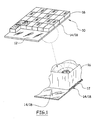
figure 1 : une vue d'une dalle réalisée avec des blochets bois de bout selon l'invention, -
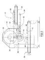
figure 2 : une vue en élévation latérale du dispositif de préparation des blochets, et -
figure 3 : une vue de face du dispositif de lafigure 2 . - Sur la
figure 1 , la dalle 10 comprend un support 12, une interface 14 adhésive et des blochets 16 de bois de bout rapportés sur ladite interface. - Le support 12 est avantageusement une mousse de forte densité pour limiter la compressibilité donc pour limiter les déplacements verticaux. Cette mousse doit néanmoins conserver une souplesse pour faciliter la mise en place des dalles pour la réalisation d'un revêtement de sol complet.
- Le rôle de cette mousse est une isolation phonique mais surtout cette mousse permet de supporter, de maintenir et de positionner les blochets.
- L'interface 14 comporte une couche d'un adhésif 18 repositionnable. Un tel adhésif adhère à la surface supérieure du support 12 et reçoit les blochets 16. Ces blochets peuvent être plaqués sur l'adhésif et se trouvent solidarisés audit support mais ils peuvent être retirés sans endommager l'adhésif et sans lui faire perdre ses capacités adhésives, ce qui est le propre d'un adhésif repositionnable. Le recours à ce type d'adhésif est important car il permet aussi de retirer un blochet pour en permettre la découpe par exemple notamment en bord de revêtement.
- Les blochets sont disposés parfaitement juxtaposés sans espace destiné à permettre une dilatation et sans espace destiné à recevoir un matériau de jointoiement.
- Les blochets se dilatent et la dilatation horizontale est reportée sur les bords libres du revêtement de sol, en périphérie.
- De façon connue, la pièce recevant le revêtement de sol comprend des moyens de compensation de la dilatation horizontale en périphérie, du type élastomère compressible, interposé entre le mur et le revêtement.
- Une des solutions consiste aussi à mettre en oeuvre le procédé selon l'invention qui conduit à l'obtention de blochets ayant des dilatations limitées qui autorisent ainsi une pose juxtaposée.
- Le procédé consiste à préparer des carrelets de bois ayant des dimensions de 0,30m à 1,5m pour disposer d'une grande rectitude. La section retenue est carrée avec des côtés de 80mm pour donner un ordre d'idées.
- Ce carrelet selon le procédé est débité par sciage transversal.
- Les blochets obtenus après sciage sont ensuite séchés, par tout moyen adapté et notamment en étuve.
- Cette étape particulière du procédé permet de sécher les blochets dans des conditions satisfaisantes.
- En effet, la migration de l'eau est beaucoup plus rapide, beaucoup plus homogène, s'effectue avec des gradients limités du fait des dimensions réduites des blochets.
- De plus, les éventuelles déformations sont extrêmement limitées car la longueur des fibres est très courte, puisque la longueur des fibres correspond à l'épaisseur du blochet. Le relâchement des contraintes s'effectue sans problème.
- Un autre avantage important concerne la qualité d'homogénéité des blochets puisqu'ils sont tous de mêmes dimensions, issus de la même essence de bois.
- Le réglage des paramètres de séchage peut être optimisé puisque tous les blochets ont strictement les mêmes dimensions.
- Dans tous les cas ces déformations sont parfaitement compatibles avec la précision dimensionnelle nécessaire pour un revêtement de sol sachant qu'elles pourront être éliminées lors d' un ponçage final après pose, si nécessaire.
- Lors d'une utilisation de carrelets débités dans du bois déjà séché à coeur, il faut recourir à du bois ayant généralement subi un séchage poussé jusqu' à un taux d'hygrométrie de 10%. Pour cela, il faut des durées de séchage très longues. La durée doit être longue pour faire migrer l'eau sans engendrer trop de contraintes différentielles dans le bois mais elle doit être suffisamment courte pour que l'opération ne soit pas trop coûteuse.
- Du fait de ce compromis nécessaire, du fait de la disparité des dimensions des pièces de bois généralement séchées simultanément, il subsiste des contraintes dans le bois.
- C'est à partir de telles pièces de bois de différentes longueurs que sont découpés des carrelets eux-mêmes de différentes longueurs.
- Or, on a constaté que les contraintes de séchage du bois subsistent dans le carrelet et se relâchent souvent après découpe des blochets engendrant des déformations non acceptables.
- Le fait de recourir à du bois séché à coeur n'est pas la solution sans compter les pertes constituées par la sciure et par les chutes qui ont été des volumes de bois séchés inutilement.
- On sait aussi qu'il y a des défauts dans le bois et certains blochets découpés sont inacceptables. Ces blochets mis au rebut sont aussi du bois séché à coeur inutilement de même que les blochets dont les déformations sont trop importantes.
- Le procédé selon l'invention qui consiste à utiliser du bois brut permet aussi de façon avantageuse de ne sécher que le volume de bois strictement utile, sans sécher inutilement le volume de bois correspondant aux chutes lors du débit des pièces de bois pour l'obtention des carrelets, à la sciure de coupe des blochets, aux chutes issues du débit des carrelets et aux blochets rejetés comme non conformes.
- Le procédé selon l'invention permet de vaincre un préjugé et diminue ainsi fortement les coûts d'obtention des blochets en plus d'en améliorer la qualité au moins en ce qui concerne la qualité du respect dimensionnel et l' homogénéité de réalisation.
- Une autre solution consiste à recourir à des carrelets débités dans des pièces de bois de plus petites dimensions, sous multiples dimensionnels d'un blochet. Ainsi un blochet de 80 mm de côté comprend quatre pièces de 20 mm par 80 mm pour la même hauteur, nécessairement. Les pièces découpées sont séchées puis ces pièces sont assemblées par collage comme du lamellé collé.
- Ces carrelets sont alors très stables dimensionnellement et les pièces de bois sont de sections encore plus petites unitairement ce qui améliore encore le séchage et le relâchement des contraintes mais modifie l'aspect esthétique final.
- Il subsiste ensuite les contraintes d'une découpe de qualité des carrelets pour mettre en oeuvre ce procédé et obtenir des blochets adaptés.
- C'est l'objet du dispositif qui est maintenant décrit en regard des
figures 2 et3 . - Les carrelets 20 de section identique ont des longueurs différentes fonction des pièces de bois dont ils sont issus. Ces carrelets sont positionnés à l'entrée du dispositif.
- Le dispositif de découpe de blochets selon l' invention, comprend un poste 22 d'alimentation un poste 24 de découpe par sciage et un poste 26 d'évacuation. Le poste 22 d'alimentation comprend un convoyeur 28 supportant les carrelets 20.
- Ce convoyeur 28 alimente un plateau 30 de positionnement. Ce plateau comporte un premier vérin 32 de calage, perpendiculaire au sens d'alimentation pour mettre le carrelet en butée par une de ses extrémités, non visible sur les figures.
- Le plateau 30 de positionnement comprend un vérin 34 pousseur qui poursuit le déplacement du carrelet 20 ainsi positionné en butée vers le poste 24 de découpe par sciage. Ce plateau est découpé à son extrémité pour constituer un peigne.
- Ce poste 24 de découpe par sciage comprend un arbre 36, entraîné par un moteur M1, portant une succession de disques 38 tranchants. Les disques 38 sont espacés par des entretoises par exemple, de façon à obtenir entre deux disques successifs un espace égal à l'épaisseur déterminée pour les blochets, ceci de façon précise.
- L'épaisseur des disques se traduit par la production de sciure, comme dans toute opération de sciage. Cette épaisseur doit être limitée pour réduire les pertes mais suffisante pour conserver les disques rigides et éviter les vibrations dans les conditions de sciage prévues.
- De même, le profil de denture doit être adapté pour atteindre le meilleur compromis entre vitesse de coupe, attaque du bois sans éclat, fin de coupe sans éclat, limitation des échauffements pour ne pas dégrader la surface de coupe puisque cette surface est directement visible après la pose.
- Afin d'obtenir une très grande précision de coupe et de limiter très fortement les éclats, il est prévu des moyens 40 de guidage de coupe. Ces moyens 40 de guidage comprennent un arbre 42 portant au moins une série de doigts 44, entraîné en rotation par un moteur M2.
- Le moteur M2 est moins puissant que le moteur M1 puisqu'il presse seulement les carrelets comme expliqué tandis que M1 doit entraîner de nombreux disques coupants dont la vitesse doit rester quasiment constante à vide comme lors de la coupe.
- Chaque extrémité de doigt a un profil destiné à coopérer avec celui d'un carrelet. En l' occurrence le profil est en L. Il est aussi prévu une butée 46, de forme courbe par exemple un barreau de façon à maintenir le carrelet dans le profil en L durant la coupe.
- Les doigts ont une largeur et une disposition telles qu'ils peuvent passer entre les disques. Les doigts sont prévus pour amener chaque carrelet à la coupe par les disques sur toute sa section.
- De façon préférentielle, il est prévu deux séries de doigts disposées à 180°.
- Les deux arbres 36 et 42 sont alignés verticalement.
- En partie inférieure du dispositif, il est prévu des moyens 26 d'évacuation avec un convoyeur 48 destiné à recueillir les blochets ainsi venus de coupe.
- Le dispositif fonctionne de la façon suivante :
- Les carrelets 20 sont approvisionnés par le convoyeur 28. Un carrelet translaté tombe sur le plateau 30, ce carrelet est mis en butée par le vérin 32 puis poussé vers le poste 24 de découpe par le vérin 34.
- L'arbre 36 est entraîné en continu par le moteur M1 à la vitesse de coupe adaptée.
- Lorsque le carrelet 20 est en place sur le plateau 30, le moteur M2 en rotation lente déplace une série de doigts 44 qui viennent cueillir le carrelet, le soulèvent et le déplacent à travers les disques 38 pour obtenir une découpe sur toute la section.
- La qualité de cette découpe est améliorée encore par le fait que le carrelet 20 décrit une trajectoire curviligne.
- Les blochets 16 ainsi découpés chutent sur le convoyeur 48.
- Ces blochets 16 sont ainsi prêts pour être séchés.
- Ces blochets, une fois séchés, peuvent être utilisés pour réaliser des dalles 10.
Claims (6)
- Procédé de réalisation d'une dalle composée de blochets de bois de bout, caractérisé en ce qu'il comprend les étapes suivantes:- préparer des blochets (16) de bois de bout, par découpe transversale par sciage d'un carrelet (20),- préparer un support (12) de forte densité pour limiter la compressibilité,- préparer une interface (14) adhésive avec une couche d'un adhésif (18) repositionnable,- disposer les blochets (16) sur cette interface (14).
- Procédé de réalisation d'une dalle selon la revendication 1, caractérisé en ce que le support (12) est une mousse de forte densité pour limiter la compressibilité et pour limiter les déplacements verticaux.
- Dispositif de réalisation de blochets pour la mise en oeuvre du procédé selon la revendication 1 et 2, comprenant un poste (22) d'alimentation en carrelets (20), un poste (24) de découpe par sciage multiple comprenant un arbre (36) motorisé avec un arbre comportant une succession de disques (38) tranchants et avec des moyens (40) de guidage de coupe comprenant un arbre (42) entraîné en rotation par un moteur M2, ledit arbre (42) portant au moins une série de doigts (44) ayant un profil destiné à coopérer avec celui d'un carrelet et aptes à passer entre les disques, ainsi qu'un poste (26) d'évacuation.
- Dispositif de réalisation de blochets selon la revendication 3, caractérisé en ce que le poste (22) d'alimentation comprend un convoyeur (28) supportant les carrelets de façon à alimenter un plateau (30) de positionnement, un premier vérin (32) de calage, perpendiculaire au sens d'alimentation pour mettre le carrelet en butée par une de ses extrémités et un vérin (34) pousseur pour déplacer le carrelet (20) ainsi positionné en butée vers le poste (24) de découpe par sciage.
- Dispositif de réalisation de brochets selon la revendication 3 ou 4, caractérisé en ce que les disques (38) sont espacés de façon à obtenir entre deux disques successifs un espace égal à l'épaisseur d'un blochet, les doigts (44) pressant les carrelets sur lesdits disques (38).
- Dispositif de réalisation de blochets selon les revendications 3 et 5, caractérisé en ce que les arbres (36) et (42) du poste (24) de découpe par sciage et des moyens (40) de guidage sont alignés.
Applications Claiming Priority (3)
| Application Number | Priority Date | Filing Date | Title |
|---|---|---|---|
| FR0755193A FR2916465A1 (fr) | 2007-05-22 | 2007-05-22 | Procede et dispositif de realisation d'une dalle en blochets de bois de bout. |
| US97684607P | 2007-10-02 | 2007-10-02 | |
| PCT/FR2008/050890 WO2008149034A1 (fr) | 2007-05-22 | 2008-05-22 | Procede et dispositif de realisation d'une dalle en blochets de bois de bout |
Publications (2)
| Publication Number | Publication Date |
|---|---|
| EP2158071A1 EP2158071A1 (fr) | 2010-03-03 |
| EP2158071B1 true EP2158071B1 (fr) | 2014-07-09 |
Family
ID=38847037
Family Applications (1)
| Application Number | Title | Priority Date | Filing Date |
|---|---|---|---|
| EP08805834.2A Not-in-force EP2158071B1 (fr) | 2007-05-22 | 2008-05-22 | Procede et dispositif de realisation d'une dalle en blochets de bois de bout |
Country Status (5)
| Country | Link |
|---|---|
| US (1) | US20100163176A1 (fr) |
| EP (1) | EP2158071B1 (fr) |
| CA (1) | CA2687727A1 (fr) |
| FR (1) | FR2916465A1 (fr) |
| WO (1) | WO2008149034A1 (fr) |
Families Citing this family (3)
| Publication number | Priority date | Publication date | Assignee | Title |
|---|---|---|---|---|
| SI23034A (sl) * | 2009-04-06 | 2010-10-29 | Žnidarec Miran | Lesna obloga |
| US20110030300A1 (en) * | 2009-08-10 | 2011-02-10 | Liu David C | Floor And Tile With Padding |
| CN105666588B (zh) * | 2016-01-26 | 2018-12-18 | 衢州熊妮妮计算机科技有限公司 | 一种块状废旧木料切削装置 |
Family Cites Families (15)
| Publication number | Priority date | Publication date | Assignee | Title |
|---|---|---|---|---|
| US1815222A (en) * | 1928-03-10 | 1931-07-21 | Justin R Swift | Gang saw |
| US2664926A (en) * | 1949-08-03 | 1954-01-05 | Winona Tool Mfg Company | Automatic lumber-releasing traveling gang saw sawmill |
| FR1117506A (fr) * | 1954-12-10 | 1956-05-23 | Plancher constitué par l'assemblage de blocs de bois sectionnes perpendiculairementau sens des fibres | |
| US3118804A (en) * | 1957-05-06 | 1964-01-21 | Wood Products Dev Company Inc | Apparatus for making parquet flooring blocks |
| US2961021A (en) * | 1957-06-18 | 1960-11-22 | Wood Products Dev Company Inc | Method of and apparatus for making parquet flooring blocks |
| US2983295A (en) * | 1958-01-29 | 1961-05-09 | Wood Products Dev Company Inc | Wooden parquet flooring block and method and apparatus for producing the same |
| US2983361A (en) * | 1958-03-31 | 1961-05-09 | Wood Products Dev Company Inc | Apparatus for making parquet flooring blocks |
| FR1321924A (fr) * | 1962-05-09 | 1963-03-22 | Parquet mosaïque préfabriqué en bois debout | |
| GB910376A (en) * | 1965-06-24 | 1962-11-14 | Frank Rebick | Machine for manufacturing flooring tiles |
| EP0139660B1 (fr) * | 1983-02-25 | 1988-10-19 | GUILMIN, Edouard Georges Paul | Procede pour confectionner un parquet a partir de blocs de bois de bout |
| SE459486B (sv) * | 1986-06-18 | 1989-07-10 | Waco Jonsereds Ab | Saett och anordning foer klyvning och bearbetning av braedor med godtycklig bredd till lameller |
| US4881584A (en) * | 1989-01-09 | 1989-11-21 | Weyerhaeuser Company | Infeed conveyor for saw |
| US5099896A (en) * | 1991-04-24 | 1992-03-31 | Harvey Industries, Inc | Rotary board pick/store/place method and apparatus |
| US6612216B2 (en) * | 2000-02-23 | 2003-09-02 | Cae, Inc. | Active sawguide assembly and method |
| US7114609B2 (en) * | 2005-02-08 | 2006-10-03 | Paper Converting Machine Company | Product diverter and method |
-
2007
- 2007-05-22 FR FR0755193A patent/FR2916465A1/fr not_active Withdrawn
-
2008
- 2008-05-22 EP EP08805834.2A patent/EP2158071B1/fr not_active Not-in-force
- 2008-05-22 CA CA002687727A patent/CA2687727A1/fr not_active Abandoned
- 2008-05-22 WO PCT/FR2008/050890 patent/WO2008149034A1/fr not_active Ceased
- 2008-05-22 US US12/601,490 patent/US20100163176A1/en not_active Abandoned
Also Published As
| Publication number | Publication date |
|---|---|
| EP2158071A1 (fr) | 2010-03-03 |
| WO2008149034A1 (fr) | 2008-12-11 |
| CA2687727A1 (fr) | 2008-12-11 |
| FR2916465A1 (fr) | 2008-11-28 |
| US20100163176A1 (en) | 2010-07-01 |
Similar Documents
| Publication | Publication Date | Title |
|---|---|---|
| EP0176388B1 (fr) | Installation pour la fabrication des vitrages multiples à joints en matières plastiques | |
| US20100178451A1 (en) | Method for producing bamboo boards and products | |
| EP2158071B1 (fr) | Procede et dispositif de realisation d'une dalle en blochets de bois de bout | |
| EP0240418B1 (fr) | Procédé et dispositif de formage du verre | |
| FR2493210A1 (fr) | Procede et dispositif pour couper une structure complexe et allongee | |
| EP3571361A1 (fr) | Panneau acoustique pour la realisation d'un revetement de sol | |
| CN104209994B (zh) | 一种木板刺口斩断纤维的细木工板及制作工艺 | |
| CN104827541B (zh) | 一种高出材率云杉无缺陷径切板材的下锯方法 | |
| CN103826817B (zh) | 用香蕉茎制造板的方法以及用如此方法生产的板 | |
| EP3744492B1 (fr) | Procédé de fabrication de panneaux de bois massif multicouche | |
| FR2866370A1 (fr) | Plaques a base de liant hydraulique a bords amincis, procede de fabrication de plaques a base de liant hydraulique et ligne de production de telles plaques, et procede de construction de second oeuvre | |
| WO2004009309A2 (fr) | Procede de fabrication de plaques a bords amincis, a base de liants hydrauliques, ligne et dispositif pour la production de telles plaques | |
| EP1670622B1 (fr) | Methode et systeme pour chauffer des billes gelees | |
| EP3429791B1 (fr) | Procede de decoupe d'un matelas, d'un panneau ou d'une plaque en laine minerale ou materiau de construction poreux | |
| EP3328637B1 (fr) | Panneau de bois multicouche et procede de decoupe et d'assemblage d'avives de bois a l'etat vert pour la fabrication d'un tel panneau | |
| EP0056354A1 (fr) | Procédé et installation pour la fabrication de panneaux en mousse expansée | |
| FR2794052A1 (fr) | Procede et installation de fabrication d'un coffre de reception d'un volet roulant | |
| FR2677692A1 (fr) | Poutre economique en lamelle-colle, procede de fabrication et machine pour le mettre en óoeuvre. | |
| BE1016294A5 (fr) | Procede et dispositif de fabrication de polystyrene expanse. | |
| JP5154474B2 (ja) | 木材の耐光処理方法 | |
| EP1448347A1 (fr) | Procede de fabrication de plaques a bords amincis, a base de liants hydrauliques, ligne et dispositif pour la production de telles plaques | |
| FR3084280A1 (fr) | Panneau composite bio-source presentant une surface de rugosite controlee et precedes de fabrication associes | |
| FR2536325A1 (fr) | Procede et dispositif pour la fabrication en continu de bois lamelle par autoserrage | |
| FR2986809A1 (fr) | Bloc de construction a portion ajustee, procede de fabrication et ouvrage obtenu | |
| EP1803868A1 (fr) | Produit de revêtement de sol, mur ou autre surface de bâtiment, ainsi que procédé et dispositif de fabrication associés |
Legal Events
| Date | Code | Title | Description |
|---|---|---|---|
| PUAI | Public reference made under article 153(3) epc to a published international application that has entered the european phase |
Free format text: ORIGINAL CODE: 0009012 |
|
| 17P | Request for examination filed |
Effective date: 20091120 |
|
| AK | Designated contracting states |
Kind code of ref document: A1 Designated state(s): AT BE BG CH CY CZ DE DK EE ES FI FR GB GR HR HU IE IS IT LI LT LU LV MC MT NL NO PL PT RO SE SI SK TR |
|
| AX | Request for extension of the european patent |
Extension state: AL BA MK RS |
|
| 17Q | First examination report despatched |
Effective date: 20100629 |
|
| DAX | Request for extension of the european patent (deleted) | ||
| REG | Reference to a national code |
Ref country code: DE Ref legal event code: R079 Ref document number: 602008033223 Country of ref document: DE Free format text: PREVIOUS MAIN CLASS: B27M0003040000 Ipc: B23D0045100000 |
|
| RIC1 | Information provided on ipc code assigned before grant |
Ipc: E04F 15/16 20060101ALI20131127BHEP Ipc: E04F 15/04 20060101ALI20131127BHEP Ipc: B23D 45/10 20060101AFI20131127BHEP Ipc: B27M 3/04 20060101ALI20131127BHEP |
|
| GRAP | Despatch of communication of intention to grant a patent |
Free format text: ORIGINAL CODE: EPIDOSNIGR1 |
|
| INTG | Intention to grant announced |
Effective date: 20140122 |
|
| GRAS | Grant fee paid |
Free format text: ORIGINAL CODE: EPIDOSNIGR3 |
|
| GRAA | (expected) grant |
Free format text: ORIGINAL CODE: 0009210 |
|
| AK | Designated contracting states |
Kind code of ref document: B1 Designated state(s): AT BE BG CH CY CZ DE DK EE ES FI FR GB GR HR HU IE IS IT LI LT LU LV MC MT NL NO PL PT RO SE SI SK TR |
|
| REG | Reference to a national code |
Ref country code: GB Ref legal event code: FG4D Free format text: NOT ENGLISH |
|
| REG | Reference to a national code |
Ref country code: AT Ref legal event code: REF Ref document number: 676389 Country of ref document: AT Kind code of ref document: T Effective date: 20140715 Ref country code: CH Ref legal event code: EP |
|
| REG | Reference to a national code |
Ref country code: IE Ref legal event code: FG4D Free format text: LANGUAGE OF EP DOCUMENT: FRENCH |
|
| REG | Reference to a national code |
Ref country code: DE Ref legal event code: R096 Ref document number: 602008033223 Country of ref document: DE Effective date: 20140821 |
|
| REG | Reference to a national code |
Ref country code: AT Ref legal event code: MK05 Ref document number: 676389 Country of ref document: AT Kind code of ref document: T Effective date: 20140709 |
|
| REG | Reference to a national code |
Ref country code: NL Ref legal event code: VDEP Effective date: 20140709 |
|
| REG | Reference to a national code |
Ref country code: LT Ref legal event code: MG4D |
|
| PG25 | Lapsed in a contracting state [announced via postgrant information from national office to epo] |
Ref country code: FI Free format text: LAPSE BECAUSE OF FAILURE TO SUBMIT A TRANSLATION OF THE DESCRIPTION OR TO PAY THE FEE WITHIN THE PRESCRIBED TIME-LIMIT Effective date: 20140709 Ref country code: NO Free format text: LAPSE BECAUSE OF FAILURE TO SUBMIT A TRANSLATION OF THE DESCRIPTION OR TO PAY THE FEE WITHIN THE PRESCRIBED TIME-LIMIT Effective date: 20141009 Ref country code: GR Free format text: LAPSE BECAUSE OF FAILURE TO SUBMIT A TRANSLATION OF THE DESCRIPTION OR TO PAY THE FEE WITHIN THE PRESCRIBED TIME-LIMIT Effective date: 20141010 Ref country code: LT Free format text: LAPSE BECAUSE OF FAILURE TO SUBMIT A TRANSLATION OF THE DESCRIPTION OR TO PAY THE FEE WITHIN THE PRESCRIBED TIME-LIMIT Effective date: 20140709 Ref country code: SE Free format text: LAPSE BECAUSE OF FAILURE TO SUBMIT A TRANSLATION OF THE DESCRIPTION OR TO PAY THE FEE WITHIN THE PRESCRIBED TIME-LIMIT Effective date: 20140709 Ref country code: PT Free format text: LAPSE BECAUSE OF FAILURE TO SUBMIT A TRANSLATION OF THE DESCRIPTION OR TO PAY THE FEE WITHIN THE PRESCRIBED TIME-LIMIT Effective date: 20141110 Ref country code: BG Free format text: LAPSE BECAUSE OF FAILURE TO SUBMIT A TRANSLATION OF THE DESCRIPTION OR TO PAY THE FEE WITHIN THE PRESCRIBED TIME-LIMIT Effective date: 20141009 Ref country code: ES Free format text: LAPSE BECAUSE OF FAILURE TO SUBMIT A TRANSLATION OF THE DESCRIPTION OR TO PAY THE FEE WITHIN THE PRESCRIBED TIME-LIMIT Effective date: 20140709 |
|
| PG25 | Lapsed in a contracting state [announced via postgrant information from national office to epo] |
Ref country code: CY Free format text: LAPSE BECAUSE OF FAILURE TO SUBMIT A TRANSLATION OF THE DESCRIPTION OR TO PAY THE FEE WITHIN THE PRESCRIBED TIME-LIMIT Effective date: 20140709 Ref country code: NL Free format text: LAPSE BECAUSE OF FAILURE TO SUBMIT A TRANSLATION OF THE DESCRIPTION OR TO PAY THE FEE WITHIN THE PRESCRIBED TIME-LIMIT Effective date: 20140709 Ref country code: LV Free format text: LAPSE BECAUSE OF FAILURE TO SUBMIT A TRANSLATION OF THE DESCRIPTION OR TO PAY THE FEE WITHIN THE PRESCRIBED TIME-LIMIT Effective date: 20140709 Ref country code: AT Free format text: LAPSE BECAUSE OF FAILURE TO SUBMIT A TRANSLATION OF THE DESCRIPTION OR TO PAY THE FEE WITHIN THE PRESCRIBED TIME-LIMIT Effective date: 20140709 Ref country code: PL Free format text: LAPSE BECAUSE OF FAILURE TO SUBMIT A TRANSLATION OF THE DESCRIPTION OR TO PAY THE FEE WITHIN THE PRESCRIBED TIME-LIMIT Effective date: 20140709 Ref country code: IS Free format text: LAPSE BECAUSE OF FAILURE TO SUBMIT A TRANSLATION OF THE DESCRIPTION OR TO PAY THE FEE WITHIN THE PRESCRIBED TIME-LIMIT Effective date: 20141109 Ref country code: HR Free format text: LAPSE BECAUSE OF FAILURE TO SUBMIT A TRANSLATION OF THE DESCRIPTION OR TO PAY THE FEE WITHIN THE PRESCRIBED TIME-LIMIT Effective date: 20140709 |
|
| REG | Reference to a national code |
Ref country code: DE Ref legal event code: R097 Ref document number: 602008033223 Country of ref document: DE |
|
| PG25 | Lapsed in a contracting state [announced via postgrant information from national office to epo] |
Ref country code: CZ Free format text: LAPSE BECAUSE OF FAILURE TO SUBMIT A TRANSLATION OF THE DESCRIPTION OR TO PAY THE FEE WITHIN THE PRESCRIBED TIME-LIMIT Effective date: 20140709 Ref country code: RO Free format text: LAPSE BECAUSE OF FAILURE TO SUBMIT A TRANSLATION OF THE DESCRIPTION OR TO PAY THE FEE WITHIN THE PRESCRIBED TIME-LIMIT Effective date: 20140709 Ref country code: IT Free format text: LAPSE BECAUSE OF FAILURE TO SUBMIT A TRANSLATION OF THE DESCRIPTION OR TO PAY THE FEE WITHIN THE PRESCRIBED TIME-LIMIT Effective date: 20140709 Ref country code: EE Free format text: LAPSE BECAUSE OF FAILURE TO SUBMIT A TRANSLATION OF THE DESCRIPTION OR TO PAY THE FEE WITHIN THE PRESCRIBED TIME-LIMIT Effective date: 20140709 Ref country code: DK Free format text: LAPSE BECAUSE OF FAILURE TO SUBMIT A TRANSLATION OF THE DESCRIPTION OR TO PAY THE FEE WITHIN THE PRESCRIBED TIME-LIMIT Effective date: 20140709 Ref country code: SK Free format text: LAPSE BECAUSE OF FAILURE TO SUBMIT A TRANSLATION OF THE DESCRIPTION OR TO PAY THE FEE WITHIN THE PRESCRIBED TIME-LIMIT Effective date: 20140709 |
|
| PLBE | No opposition filed within time limit |
Free format text: ORIGINAL CODE: 0009261 |
|
| STAA | Information on the status of an ep patent application or granted ep patent |
Free format text: STATUS: NO OPPOSITION FILED WITHIN TIME LIMIT |
|
| REG | Reference to a national code |
Ref country code: FR Ref legal event code: PLFP Year of fee payment: 8 |
|
| 26N | No opposition filed |
Effective date: 20150410 |
|
| PGFP | Annual fee paid to national office [announced via postgrant information from national office to epo] |
Ref country code: FR Payment date: 20150529 Year of fee payment: 8 |
|
| PG25 | Lapsed in a contracting state [announced via postgrant information from national office to epo] |
Ref country code: SI Free format text: LAPSE BECAUSE OF FAILURE TO SUBMIT A TRANSLATION OF THE DESCRIPTION OR TO PAY THE FEE WITHIN THE PRESCRIBED TIME-LIMIT Effective date: 20140709 |
|
| REG | Reference to a national code |
Ref country code: DE Ref legal event code: R119 Ref document number: 602008033223 Country of ref document: DE |
|
| REG | Reference to a national code |
Ref country code: CH Ref legal event code: PL |
|
| GBPC | Gb: european patent ceased through non-payment of renewal fee |
Effective date: 20150522 |
|
| PG25 | Lapsed in a contracting state [announced via postgrant information from national office to epo] |
Ref country code: LU Free format text: LAPSE BECAUSE OF FAILURE TO SUBMIT A TRANSLATION OF THE DESCRIPTION OR TO PAY THE FEE WITHIN THE PRESCRIBED TIME-LIMIT Effective date: 20150522 Ref country code: LI Free format text: LAPSE BECAUSE OF NON-PAYMENT OF DUE FEES Effective date: 20150531 Ref country code: CH Free format text: LAPSE BECAUSE OF NON-PAYMENT OF DUE FEES Effective date: 20150531 Ref country code: MC Free format text: LAPSE BECAUSE OF FAILURE TO SUBMIT A TRANSLATION OF THE DESCRIPTION OR TO PAY THE FEE WITHIN THE PRESCRIBED TIME-LIMIT Effective date: 20140709 |
|
| REG | Reference to a national code |
Ref country code: IE Ref legal event code: MM4A |
|
| PG25 | Lapsed in a contracting state [announced via postgrant information from national office to epo] |
Ref country code: DE Free format text: LAPSE BECAUSE OF NON-PAYMENT OF DUE FEES Effective date: 20151201 Ref country code: IE Free format text: LAPSE BECAUSE OF NON-PAYMENT OF DUE FEES Effective date: 20150522 Ref country code: GB Free format text: LAPSE BECAUSE OF NON-PAYMENT OF DUE FEES Effective date: 20150522 |
|
| PG25 | Lapsed in a contracting state [announced via postgrant information from national office to epo] |
Ref country code: MT Free format text: LAPSE BECAUSE OF FAILURE TO SUBMIT A TRANSLATION OF THE DESCRIPTION OR TO PAY THE FEE WITHIN THE PRESCRIBED TIME-LIMIT Effective date: 20140709 |
|
| REG | Reference to a national code |
Ref country code: FR Ref legal event code: ST Effective date: 20170131 |
|
| PG25 | Lapsed in a contracting state [announced via postgrant information from national office to epo] |
Ref country code: FR Free format text: LAPSE BECAUSE OF NON-PAYMENT OF DUE FEES Effective date: 20160531 |
|
| PG25 | Lapsed in a contracting state [announced via postgrant information from national office to epo] |
Ref country code: HU Free format text: LAPSE BECAUSE OF FAILURE TO SUBMIT A TRANSLATION OF THE DESCRIPTION OR TO PAY THE FEE WITHIN THE PRESCRIBED TIME-LIMIT; INVALID AB INITIO Effective date: 20080522 |
|
| PG25 | Lapsed in a contracting state [announced via postgrant information from national office to epo] |
Ref country code: BE Free format text: LAPSE BECAUSE OF NON-PAYMENT OF DUE FEES Effective date: 20150531 |
|
| PG25 | Lapsed in a contracting state [announced via postgrant information from national office to epo] |
Ref country code: TR Free format text: LAPSE BECAUSE OF FAILURE TO SUBMIT A TRANSLATION OF THE DESCRIPTION OR TO PAY THE FEE WITHIN THE PRESCRIBED TIME-LIMIT Effective date: 20140709 |