EP2159850B1 - Dachstein, insbesondere Dachziegel - Google Patents
Dachstein, insbesondere Dachziegel Download PDFInfo
- Publication number
- EP2159850B1 EP2159850B1 EP09010802A EP09010802A EP2159850B1 EP 2159850 B1 EP2159850 B1 EP 2159850B1 EP 09010802 A EP09010802 A EP 09010802A EP 09010802 A EP09010802 A EP 09010802A EP 2159850 B1 EP2159850 B1 EP 2159850B1
- Authority
- EP
- European Patent Office
- Prior art keywords
- roof tile
- recess
- solar
- roof
- edge
- Prior art date
- Legal status (The legal status is an assumption and is not a legal conclusion. Google has not performed a legal analysis and makes no representation as to the accuracy of the status listed.)
- Active
Links
Images



Classifications
-
- H—ELECTRICITY
- H02—GENERATION; CONVERSION OR DISTRIBUTION OF ELECTRIC POWER
- H02S—GENERATION OF ELECTRIC POWER BY CONVERSION OF INFRARED RADIATION, VISIBLE LIGHT OR ULTRAVIOLET LIGHT, e.g. USING PHOTOVOLTAIC [PV] MODULES
- H02S20/00—Supporting structures for PV modules
- H02S20/20—Supporting structures directly fixed to an immovable object
- H02S20/22—Supporting structures directly fixed to an immovable object specially adapted for buildings
- H02S20/23—Supporting structures directly fixed to an immovable object specially adapted for buildings specially adapted for roof structures
- H02S20/25—Roof tile elements
-
- Y—GENERAL TAGGING OF NEW TECHNOLOGICAL DEVELOPMENTS; GENERAL TAGGING OF CROSS-SECTIONAL TECHNOLOGIES SPANNING OVER SEVERAL SECTIONS OF THE IPC; TECHNICAL SUBJECTS COVERED BY FORMER USPC CROSS-REFERENCE ART COLLECTIONS [XRACs] AND DIGESTS
- Y02—TECHNOLOGIES OR APPLICATIONS FOR MITIGATION OR ADAPTATION AGAINST CLIMATE CHANGE
- Y02B—CLIMATE CHANGE MITIGATION TECHNOLOGIES RELATED TO BUILDINGS, e.g. HOUSING, HOUSE APPLIANCES OR RELATED END-USER APPLICATIONS
- Y02B10/00—Integration of renewable energy sources in buildings
- Y02B10/10—Photovoltaic [PV]
-
- Y—GENERAL TAGGING OF NEW TECHNOLOGICAL DEVELOPMENTS; GENERAL TAGGING OF CROSS-SECTIONAL TECHNOLOGIES SPANNING OVER SEVERAL SECTIONS OF THE IPC; TECHNICAL SUBJECTS COVERED BY FORMER USPC CROSS-REFERENCE ART COLLECTIONS [XRACs] AND DIGESTS
- Y02—TECHNOLOGIES OR APPLICATIONS FOR MITIGATION OR ADAPTATION AGAINST CLIMATE CHANGE
- Y02E—REDUCTION OF GREENHOUSE GAS [GHG] EMISSIONS, RELATED TO ENERGY GENERATION, TRANSMISSION OR DISTRIBUTION
- Y02E10/00—Energy generation through renewable energy sources
- Y02E10/50—Photovoltaic [PV] energy
Definitions
- the invention relates to a roof tile, in particular a flat or trough roof tile with a top and a side rabbeting and with a provided in the surface of the roof tile, bounded by edges recess into which a solar element can be used, wherein the solar element in such a way in the recess the roof tile can be used, that with its lower edge it projects beyond the adjacent edge of the surface area of the roof tile and with its upper edge lies flush with the upper edge of the adjacent surface area of the roof tile or its upper edge is lower than the upper edge of the adjacent surface area of the Dachstein.
- Dachsteine of the aforementioned type are known. These are to be designed as flat tiles. However, well tiles with two or more adjacent trough sections are also known. In a training with several trough sections a roofing is made possible, in which a lower Dachsteinlage is offset from an upper by half the roof tile width, resulting in an uninterrupted joint profile. Due to the substantially identical design of the individual sections arises in a roof covered with this roof a largely uniform visual impression, because the displacement of the joints does not appear. Such large-scale roof tiles are appreciated in recent times for their advantages in transport and covering work.
- a solar roof tile which has a side fold and a Kopffalz in conventional design.
- Each individual tile receives a solar module, which in turn is also essentially box-shaped.
- the roof tiles are formed on the top with four grooves. In these grooves, the solar modules are clipped by means of a spring system.
- the roof tile in turn has next to the Soverfalzung also a box-shaped receiving space, in which the photovoltaic module is beauclipsen by means of the above-described spring technology.
- the receiving space is completely filled in the assembled state of the module.
- these systems are complex and expensive. In addition, they affect the overall visual impression of a roof sustainably.
- a photovoltaic module which has an at least two-part metallic frame into which a solar module part can be inserted. In the mounted state, the frame completely engages over the module part, so that it is inserted in the frame with a distance to the frame top side.
- the fully assembled photovoltaic module is to be integrated into a roof, which in turn influences the overall visual impression. In addition, the inserted module affects the flow of water on the roof.
- the roof tile is formed at the edge with two different height ranges, so that the upper edge projects beyond the solar element and the solar element extends beyond the lower edge of the roof tile in turn, which is favorable for a water drainage.
- a disadvantage of the previously known Dachstein is that it requires elaborate sealing measures, which are subject to considerable wear in rough everyday use. In addition, this Dachstein is only suitable for a design as a flat tile.
- the roof tile of the type mentioned is characterized in that the recess is formed at its upper edge in cross-section substantially groove-shaped and formed in the groove space formed the solar element, which is overlapped in the inserted state of a leg of the roof tile.
- a roof tile is created in which by the solar element overlapping leg not the water drain is favored, but that Solar element is to be integrated in the roof tile in low-wear manner. Seals, adhesives and the like can be provided concealed and are no longer exposed to direct sunlight, for example. Preferred dimensions, the solar element is designed as a solar foil and can therefore be used excellently in Muldenziegeln. This makes it possible to integrate such a solar roof tile optically harmonious and not perceptible for many users in a roof surface to be covered so that the film follows not only the contour but also the color of the roof by the film has a color corresponding to the Dachstein.
- a roof tile which is similar to the conventional roof tiles in terms of its shape, but can be designed as a photovoltaic roof tile by being equipped with a solar foil following its contour or a solar collector element.
- a solar foil following its contour or a solar collector element.
- the recess may be designed accordingly, that is, taper downwards and therefore have a smaller depth at the bottom in the lower edge region than in an upper edge region.
- the solar foil or the solar collector element due to its own geometric dimensions can ensure that it widens downwards.
- a solar film can be particularly useful when Muldenziegel be used.
- a solar roof tile can be integrated optically harmonious and not perceptible for many users in a roof surface to be covered in such a way that the film follows not only the contour, but also the color of the roof by the film has a color corresponding to the Dachstein.
- the tiles can be formed with one, two or more sections, each with a trough-shaped depression and an adjacent raised area, so for example, be designed as a large roof tiles, which are to be provided with a solar film.
- classic roof tiles such as the 15er formats and hollow bricks are also suitable for training as solar roof tiles as well as the shapes of the S-pans and Finkenberger pans.
- the solar film is provided in a roof tile in such a way that when the roof is roofed, the solar film of a roof tile reaches at least approximately up to that in a recess of a neighboring roof tile, so that optically represents a continuity of the solar film.
- the solar foils are to be connected to an electrical line. This can be continuous and embedded in the solar foil.
- the recess is preferably designed such that at least one edge is provided.
- at least one upper and one lower edge are provided and also a side edge, so that the film has a respective lateral and an upper and lower boundary between which the film is glued or welded or congresslaminieren such that a secure and sealed transition between the Dachstein as such and the slide is to represent.
- the solar foil is largely flush-mounted with side areas in the recess, laminated, welded or otherwise fastened in such a way that no upstanding areas that could be solved mechanically, are present. It is also possible in this way to avoid joints and cracks.
- adhesives may be transparent or colored to match the colored contour of the Dachstein.
- the film in particular in the region of maximum deflection of a solar film, may also be provided preferably to defuse the transition region between the trough of the Dachsteines and its raised longitudinal region and here to create areas that rise up such by accumulation of material that There, the opposing deflection of the film is mitigated and thus made smaller. This is hardly noticeable visually with a covered roof, since the film still follows the trough-shaped course and the raised longitudinal area, only not so much in opposite directions is bent as the Dachstein as such.
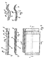
- the roof tile 1 is formed as a solar roof tile and has a recess 9, in which a solar film 10 is glued. This borders on upper and lower edges 11 and 12 and is bounded laterally by the edge 13.
- a strip of solar roof tiles can be introduced into a roof, which fits extremely harmoniously into the overall roof surface, since it has trough-shaped areas 3 and raised longitudinal areas 4 in each case. Since it can happen that the foil 10 can not take part in a maximum deflection, it is possible to provide material accumulations in the region, for example, at 15, in order to mitigate maximum deflection.
- a roof tile 1 which is formed in this embodiment as a flat roof tile 16 with a 9.verfalzung 17 and a Kopfverfalzung 18, wherein the Kopfverfalzung 18, the in Fig. 11 apparent flat brick areas 19 and in the soverfalzung 17 of the edge legs 20 is inserted, so that there is a continuous flat Dachsteinverbund in the finished laid roof.
- a generally numbered 21 recess is provided, which extends continuously up to the in Fig. 8 extends right edge 22 of the flat tile 16 and has a lower edge 23 and an upper edge 24. How to get closer from the Fig. 10 and the detail representation A after Fig.
- this upper edge 24 has a groove-shaped receiving space 25, so that a solar collector element 26 to be inserted therein (FIG. Fig. 10 ) is inserted into the nutenfömrigen space 25, after which it is overlapped by the leg 27.
- the solar collector element 26 shown there has an upper edge 28 which is inserted into the groove-shaped receiving space 25 and a lower edge 29 is formed wider than the upper edge 28. From the upper edge 28 to the lower edge 29, the solar collector element steadily wider so as to protrude at the lower edge 23 of the tile, thereby improving the watercourse on the tile and on the brick below.
- the collector 26 can be securely glued into the recess 21, so that the absolute tightness between the collector 26 and the roof stone 16 is given. If the roof tiles 16 overlap each other in the composite, results with the collector surfaces a very harmonious overall appearance of a flat roof covering:
Landscapes
- Engineering & Computer Science (AREA)
- Architecture (AREA)
- Civil Engineering (AREA)
- Structural Engineering (AREA)
- Roof Covering Using Slabs Or Stiff Sheets (AREA)
- Glass Compositions (AREA)
- Compositions Of Macromolecular Compounds (AREA)
Description
- Die Erfindung bezieht sich auf einen Dachstein , insbesondere einen Flach- oder Muldendachziegel mit einer Kopf- und einer Seitenverfalzung sowie mit einer in der Oberfläche des Dachsteins vorgesehenen, von Rändern begrenzten Ausnehmung, in die ein Solarelement einsetzbar ist, wobei das Solarelement derart in die Ausnehmung des Dachsteines einsetzbar ist, dass sie mit ihrem unteren Rand den angrenzenden Rand des Oberflächenbereiches des Dachsteines überragt und mit ihrem oberen Rand an dem oberen Rand des angrenzenden Oberflächenbereiches des Dachsteines maximal flächenbündig anliegt oder ihr obere Rand tiefer gelegen ist als der obere Rand des angrenzenden Oberflächenbereiches des Dachsteins.
- Dachsteine der vorgenannten Art sind bekannt. Diese sind als Flachziegel auszubilden. Bekannt sind jedoch auch Muldenziegel mit zwei oder mehr benachbarten Muldensektionen. Bei einer Ausbildung mit mehreren Muldensektionen ist eine Dacheindeckung ermöglicht, bei welcher eine untere Dachsteinlage gegenüber einer oberen um jeweils die halbe Dachsteinbreite versetzt ist, wodurch sich ein ununterbrochener Fugenverlauf ergibt. Durch die im wesentlichen gleiche Ausbildung der einzelnen Sektionen entsteht bei einem mit diesem Dachstein eingedeckten Dach ein weitgehend gleichförmiger optischer Eindruck, weil die Versetzung der Fugen nicht in Erscheinung tritt. Solche großflächigeren Dachsteine werden in jüngerer Vergangenheit aufgrund ihrer Vorteile beim Transport und bei Eindeckarbeiten geschätzt.
- Darüber hinaus ist in der jüngeren Vergangenheit insbesondere auch aufgrund stark gestiegener Energiepreise der Vorschlag umgesetzt worden, Dächer mit Solarsystemen zu versehen. Dazu ist eine Kombination aus Dachziegeln und Dachsteinen mit Photovoltaikmodulen zur Stromerzeugung vorgesehen. Solche Photovoltaikvolumenmodule sind kastenförmige Elemente, die auf das Dach aufzusetzen oder in dieses zu integrieren sind. Damit ist das Gesamterscheinungsbild des Daches jedoch wesentlich beeinträchtigt. In den Bereichen, in denen solche Photovoltaikmodule in das Dach zu integrieren sind, sind aufwändige Anbindungssysteme mit damit einhergehenden Dichtungsarbeiten vorzusehen.
- Darüber hinaus ist ein Solardachziegel vorgeschlagen worden, der in herkömmlicher Bauart eine Seitenfalz und eine Kopffalz aufweist. Jeder einzelne Dachziegel nimmt ein Solarmodul auf, das auch wiederum im wesentlichen kastenförmig ausgebildet ist. Dazu sind die Dachziegel auf der Oberseite mit jeweils vier Aufnahmenuten ausgebildet. In diese Aufnahmenuten werden die Solarmodule eingeclipst mittels eines Federsystems. Der Dachziegel seinerseits hat neben der Seitenverfalzung einen ebenfalls kastenförmigen Aufnahmeraum, in die das Photovoltaikmodul mittels der vorbeschriebenen Federtechnik einzuclipsen ist. Der Aufnahmeraum ist im montierten Zustand des Moduls vollflächig ausfüllt. Diese Systeme bauen jedoch aufwändig und sind teuer. Darüber hinaus beeinträchtigen sie den optischen Gesamteindruck eines Daches nachhaltig. In Zwischenräume zwischen den kastenförmigen Photovoltaikmodulen und den angrenzenden Dachziegelbereichen sind erhebliche Verschmutzungsrisiken durch Staub, Blätter und sonstige Schadstoffe und Schmutzpartikel zu befürchten, die nur dadurch zu beseitigen sind, wenn ein Modul demontiert, danach der Dachstein gereinigt und das Modul wieder montiert wird.
- Aus der
WO 00/79604 A1 - Aus der
US 2007/0199590 A1 ist ein Photovoltaikmodul bekannt, das einen zumindest zweiteiligen metallischen Rahmen aufweist, in den ein Solarmodulteil einsetzbar ist. Im montierten Zustand übergreift der Rahmen das Modulteil vollständig, so dass es in dem Rahmen mit einem Abstandsmaß zur Rahmenoberseite hin eingelegt ist. Das fertig montierte Photovoltaikmodul ist in ein Dach zu integrieren, womit wiederum der optische Gesamteindruck beeinflusst ist. Zudem ist durch das eingelegte Modul der Wasserfluss auf dem Dach beeinträchtigt. - Aus der
GB 24 31 773 A - Aus der
JP 8 144440 A - Es ist Aufgabe der vorliegenden Erfindung, einen Dachstein der eingangs genannten Art dahingehend weiter zu bilden, dass bei einem harmonischen Gesamterscheinungsbild eines mit solchen Dachsteinen eingedeckten Daches Photovoltaiksystem in verschleissarmer Gestaltung vorgesehen werden.
- Zur Lösung dieser Aufgabe zeichnet sich der Dachstein der eingangs genannten Art dadurch aus, dass die Ausnehmung an ihrem oberen Rand im Querschnitt im wesentlichen nutenförmig ausgebildet und in den gebildeten Nutenraum das Solarelement einführbar ist, das im eingeführten Zustand von einem Schenkel des Dachsteines übergriffen ist.
- Damit ist ein Dachstein geschaffen, bei dem durch den das Solarelement überlappenden Schenkel nicht der Wasserablauf sicher begünstigt ist, sondern das Solarelement in verschleißarmer Weise in den Dachziegel zu integrieren ist. Dichtungen, Klebstoffe und dgl. lassen sich verdeckt vorsehen und sind z.B. nicht mehr der direkten Sonneneinstrahlung ausgesetzt. Bevorzugtermaßen ist das Solarelement als Solarfolie ausgebildet und lässt sich deshalb hervorragend bei Muldenziegeln anwenden. Damit lässt sich ein solches Solardachstein optisch harmonisch und für viele Benutzer gar nicht wahrnehmbar in eine einzudeckende Dachfläche derart integrieren, dass die Folie nicht nur der Kontur, sondern auch der Farbe des Daches folgt, indem die Folie eine dem Dachstein entsprechende Farbgebung aufweist.
- Damit ist ein Dachstein geschaffen, der den herkömmlichen Dachsteinen von seiner Formgebung her gleicht, jedoch als Photovoltaikdachstein ausgebildet sein kann, indem er mit einer seiner Kontur folgenden Solarfolie oder einem Solarkollektorelement ausgerüstet ist. Dadurch, dass - von der Oberfläche her betrachtet - die Oberfläche der Solarfolie oder des Solar-kollektors (Solarelemente) eine andere Neigung aufweist als der Dachstein selbst, also so ausgerichtet ist, dass der Wasserlauf aufgrund des Überstandsmaßes des unteren Randes des Kollektorelementes oder der Folie gegenüber der unteren angrenzenden Oberfläche des Dachsteines niemals behindert ist, auch wenn die Solarfolie oder das Solarkollektorelement nicht exakt in die Ausnehmung eingesetzt sind. Dazu kann die Ausnehmung entsprechend ausgebildet sein, also sich nach unten hinten verjüngen und mithin unten im unteren Randbereich eine kleinere Tiefe haben als in einem oberen Randbereich. Umgekehrt kann auch die Solarfolie bzw. das Solarkollektorelement aufgrund eigener geometrischer Abmessungen sicherstellen , dass es sich nach unten hin erweitert.
- Mit einer Solarfolie läßt sich insbesondere dann arbeiten, wenn Muldenziegel verwendet werden. Damit lässt sich ein solcher Solardachstein optisch harmonisch und für viele Benutzer gar nicht wahrnehmbar in eine einzudeckende Dachfläche derart integrieren, dass die Folie nicht nur der Kontur, sondern auch der Farbe des Daches folgt, indem die Folie eine dem Dachstein entsprechende Farbgebung aufweist.
- Die Dachsteine können mit ein, zwei oder mehr Sektionen mit jeweils einer muldenförmigen Vertiefung und einem angrenzenden erhabenen Bereich ausgebildet sein, also beispielsweise auch als großflächige Dachziegel ausgebildet werden, die mit einer Solarfolie zu versehen sind. Aber auch klassische Dachziegel wie die 15er-Formate und Hohlziegel sind für eine Ausbildung als Solardachsteine ebenso geeignet wie die Formgebungen der S-Pfannen und der Finkenberger Pfannen.
- Bevorzugterweise ist die Solarfolie in einem Dachstein derart vorgesehen, dass beim eingedeckten Dach die Solarfolie eines Dachsteines zumindest annähernd bis zu der in einer Ausnehmung eines benachbart montierten Dachsteines reicht, so dass sich optisch eine Durchgängigkeit der Solarfolie darstellt. Die Solarfolien sind an eine elektrische Leitung anzuschießen. Diese kann durchgängig sein und in die Solarfolie eingelassen werden.
- Bevorzugtermaßen ist die Ausnehmung jedoch so gestaltet, dass zumindest ein Rand vorgesehen ist. Bevorzugt sind zumindest ein oberer und ein unterer Rand vorgesehen und auch noch ein Seitenrand, so dass die Folie eine jeweils seitliche und eine obere und untere Begrenzung aufweist, zwischen denen die Folie derart einzukleben bzw. einzuschweißen oder einzulaminieren ist, dass ein sicherer und abgedichteter Übergang zwischen dem Dachstein als solchem und der Folie darzustellen ist. Damit ergeben sich keinerlei Risiken hinsichtlich Verschmutzung in irgendwelchen Ritzen und Fugen und ein Ablösen beispielsweise bei höheren Windgeschwindigkeiten oder bei sonstigen mechanischen Einflüssen. Die Solarfolie ist weitestgehend flächenbündig mit Seitenbereichen in die Ausnehmung einzukleben, einzulaminieren, einzuschweißen oder sonstwie in der Weise zu befestigen, dass keine emporstehenden Bereiche, die sich mechanisch lösen könnten, vorhanden sind. Auch ist es auf diese Art und Weise möglich, Fugen und Ritzen zu vermeiden. Auch Kleber können transparent oder farbig ausgebildet sein, um der farbigen Kontur des Dachsteins zu entsprechen.
- Um insbesondere größere Belastungen der Folie zu vermeiden, insbesondere im Bereich einer maximalen Durchbiegung einer Solarfolie, kann auch bevorzugtermaßen vorgesehen sein, den Übergangsbereich zwischen der Mulde des Dachsteines und seinem erhabenen Längsbereich zu entschärfen und hier Bereiche zu schaffen, die derart durch Materialanhäufung emporstehen, dass dort die gegensinnige Durchbiegung der Folie abgemildert und somit kleiner gemacht ist. Dies ist visuell bei einem eingedeckten Dach kaum wahrzunehmen, da die Folie dem muldenförmigen Verlauf und dem erhabenen Längsbereich noch folgt, nur nicht so stark gegensinnig durchgebogen ist wie der Dachstein als solcher.
- Hinsichtlich wesentlicher weiterer Ausgestaltungen wird auf weitere Unteransprüche, die nachfolgende Beschreibung und die Zeichnung verwiesen. In der Zeichnung zeigen:
- Fig. 1
- in einer perspektivischen Darstellung ein Ausführungsbeispiel eines Dachziegels nach der Erfindung;
- Fig. 2
- Dachsteine nach dem Ausführungsbeispiel nach
Fig. 1 im eingedeckten Zustand mit benachbarten Dachsteinen, die nicht mit einer Solarfolie versehen sind, - Fig. 3
- eine Draufsicht auf das Ausführungsbeispiel nach
Fig. 1 ; - Fig. 4
- eine Seitenansicht auf das Ausführungsbeispiel nach
Fig. 3 , - Fig. 5
- eine Schnittdarstellung gemäß der Schnittlinie B-B in
Fig. 3 ; - Fig. 6
- eine Ansicht von links in
Fig. 3 , und - Fig. 7
- eine Ansicht gemäß der Schnittlinie A-A in
Fig. 3 . - Fig. 8
- eine Draufsicht auf ein Ausführungsbeispiel eines Flachziegels;
- Fig. 9
- eine Querschnittsdarstellung gemäß der Schnittlinie IX-IX in
Fig. 8 ; - Fig. 10
- eine Längsschnittdarstellung gemäß der Schnittlinie X-X in
Fig. 8 - Fig. 11
- eine perspektivische Darstellung des Ausführungsbeispiels nach
Fig. 8 ; - Fig. 12
- vergrößert die Einzelheitdarstellung D in
Fig. 10 , - Fig. 13
- vergrößert die Einzelheitdarstellung A in
Fig. 10 - In der Zeichnung sind gleichwirkende Teile mit übereinstimmenden Bezugsziffern versehen. Allgemein mit 1 ist der als Dachziegel ausgebildete Dachstein 1 beziffert, der im gezeigten Ausführungsbeispiel eine Sektion 2 aus einer muldenförmigen Vertiefung 3 und einem benachbarten erhabenen Längsbereich 4 sowie eine Seitenverfalzung 5 und eine Kopffalz 6 aufweist. Die Seitenverfalzung 5 ist im montierten Zustand von dem erhabenen Längsbereich 4 zu übergreifen. Die Kopfverfalzung 5 ist von dem Bodenbereich 7 übergriffen und gehaltert. Dies ergibt das insgesamt harmonische Bild einer Dacheindeckung 8, wie in
Fig. 2 veranschaulicht. - In dem gezeigten Ausführungsbeispiel ist der Dachstein 1 als Solardachstein ausgebildet und hat eine Ausnehmung 9, in die eine Solarfolie 10 eingeklebt ist. Diese grenzt an obere und untere Ränder 11 und 12 und ist seitlich von dem Rand 13 begrenzt. Im montierten Zustand kann in ein Dach ein Streifen aus Solardachziegeln eingebracht werden, der sich ausgesprochen harmonisch in die Gesamtdachfläche einpasst, da er jeweils muldenförmige Bereiche 3 und erhabene Längsbereiche 4 aufweist. Da es vorkommen kann, dass die Folie 10 eine maximale Durchbiegung nicht mitmachen kann, ist es möglich, im Bereich z.B. bei 15 Materialanhäufungen vorzusehen, um eine maximale Durchbiegung abzumildern.
- In den Ausführungsbeispielen nach den
Fig. 8 bis 13 ist ein alternatives Ausführungsbeispiel eines Dachsteines 1 gezeigt, der in diesem Ausführungsbeispiel als Flachdachziegel 16 ausgebildet ist mit einer Seitenverfalzung 17 und einer Kopfverfalzung 18, wobei die Kopfverfalzung 18 die inFig. 11 ersichtlichen Flachziegelbereiche 19 und in die Seitenverfalzung 17 der Randschenkel 20 einzulegen ist, so dass sich ein durchgehender flacher Dachsteinverbund im fertig verlegten Dach ergibt. In der Oberfläche des Flachziegels 16 ist eine allgemein mit 21 bezifferte Ausnehmung vorgesehen, die sich durchgehend bis zu dem inFig. 8 rechten Rand 22 des Flachziegels 16 erstreckt und einen unteren Rand 23 und einen oberen Rand 24 aufweist. Wie sich näher aus denFig. 10 und der Einzelheitdarstellung A nachFig. 13 ergibt, hat dieser obere Rand 24 einen nutenförmigen Aufnahmeraum 25, so dass ein dort einzulegendes Solarkollektorelement 26 (Fig. 10 ) einzuführen ist in den nutenfömrigen Raum 25, wonach es von dem Schenkel 27 übergriffen wird. - Wie in
Fig. 10 näher dargestellt, hat das dort dargestellte Solarkollektorelement 26 einen obereren Rand 28, der in den nutenförmigen Aufnahmeraum 25 eingeführt ist und einen unteren Rand 29 der breiter ausgebildet ist, als der obere Rand 28. Vom oberen Rand 28 bis zum unteren Rand 29 wird das Solarkollektorelement stetig breiter, so dass an dem unteren Rand 23 des Dachziegels übersteht, wodurch der Wasserlauf auf dem Ziegel und auf den sich darunter anschließenden Ziegel verbessert ist. Der Kollektor 26 kann sicher in die Ausnehmung 21 eingeklebt werden, so dass die absolute Dichtheit zwischen Kollektor 26 und dem Dachstein 16 gegeben ist. Wenn die Dachsteine 16 einander im Verbund übergreifen, ergibt sich mit den Kollektorflächen ein sehr harmonisches Gesamterscheinungsbild einer flachen Dacheindeckung:
Claims (11)
- Dachstein (1 ), insbesondere Flach- oder Muldendachziegel mit einer Kopf- (6) und einer Seitenverfalzung (5) sowie mit einer in der Oberfläche des Dachsteines vorgesehenen, von Rändern (11, 12, 13, 23, 24) begrenzten Ausnehmung (9, 21), in die ein Solarelement (26) einsetzbar ist, wobei das Solarelement (26) derart in die Ausnehmung (9) des Dachsteines einsetzbar ist, das sie mit ihrem unteren Rand (29) den angrenzenden Rand (12, 23) des Oberflächenbereiches des Dachsteins (1) überragt und mit ihrem oberen Rand (28) an dem oberen Rand (11, 24) des angrenzenden Oberflächenbereiches des Dachsteines (1) maximal flächenbündig anliegt oder ihr oberer Rand (28) tiefer gelegen ist als der obere Rand (11, 24) des angrenzenden Oberflächenbereiches des Dachsteines, dadurch gekennzeichnet, dass die Ausnehmung (21) an ihrem oberen Rand im Querschnitt im wesentlichen nutenförmig ausgebildet und in den gebildeten Nutenraum (25) das Solarelement (26) einführbar ist, das im eingeführten Zustand von einem Schenkel (27) des Dachsteines (1) übergriffen ist.
- Dachstein nach Anspruch 1, dadurch gekennzeichnet, dass das in der Ausnehmung (9) angeordnete Solarelement (26) von einem oberen und einem unteren Ausnehmungsrand (11, 12) begrenzt ist.
- Dachstein nach Anspruch 1 oder 2, dadurch gekennzeichnet, dass die Ausnehmung (9) in einem der Seitenverfalzung (5) gegenüberliegenden Bereich einen Seitenrand (13) zur Begrenzung des Solarelements (26) aufweist.
- Dachstein nach einem der Ansprüche 1 bis 3, dadurch gekennzeichnet, dass die Solarelemente (26) in die Ausnehmung (9) eingeklebt, einlaminiert oder eingeschweißt ist.
- Dachstein nach einem der Ansprüche 1 bis 4, dadurch gekennzeichnet, dass das als Solarelement (26) eine Solarfolie (10) vorgesehen ist und die Solarfolie (10) eines Dachsteins (1) in einem eingedeckten Dach (8) zumindest annähernd bis zur Solarfolie (10) eines benachbart montierten Dachsteines (1) reicht.
- Dachstein nach einem der Ansprüche 1 bis 5, dadurch gekennzeichnet, dass eine elektrische Vorsorgungsleitung für eine Solarfolie (10) in einem benachbarten Solardurchgangsziegel geführt ist.
- Dachstein nach einem der Ansprüche 1 bis 6, dadurch gekennzeichnet, dass die Ausnehmung (9) zwecks Angleichung an eine maximale Durchbiegung einer Solarfolie (10) Konturanformungen (15) aufweist.
- Dachstein nach Anspruch 7, dadurch gekennzeichnet, dass die Konturanformungen (15) durch über den Verlauf des Dachsteines (1) im Bereich seines Übergangs zwischen Mulde (3) und erhabenem Längsbereich (4) emporstehende Materialanhäufungen gebildet sind.
- Dachstein nach enem der Ansprüche 1 bis 8, dadurch gekennzeichnet, dass das Solarelement (26) eine Querschnittsgestaltung hat, die sich vom oberen Rand (28) bis zum unteren Rand (29) hin erweitert.
- Dachstein nach einem der Ansprüche 1 bis 9, dadurch gekennzeichnet, dass die Ausnehmung (21) eine Tiefe hat, die sich von ihrem oberen Rand bis zu ihrem unteren Rand verkleinert.
- Dachstein nach Anspruch 10, dadurch gekennzeichnet, dass sich die Ausnehmung (21) bis hin zu einem Seitenrand des Dachsteines (1) erstreckt, die der Seitenverfalzung (17) gegenüberliegt.
Priority Applications (1)
| Application Number | Priority Date | Filing Date | Title |
|---|---|---|---|
| PL09010802T PL2159850T3 (pl) | 2008-08-26 | 2009-08-24 | Dachówka, zwłaszcza dachówka ceramiczna |
Applications Claiming Priority (1)
| Application Number | Priority Date | Filing Date | Title |
|---|---|---|---|
| DE102008039715A DE102008039715A1 (de) | 2008-08-26 | 2008-08-26 | Dachstein, insbesondere Dachziegel |
Publications (2)
| Publication Number | Publication Date |
|---|---|
| EP2159850A1 EP2159850A1 (de) | 2010-03-03 |
| EP2159850B1 true EP2159850B1 (de) | 2012-03-07 |
Family
ID=41395382
Family Applications (1)
| Application Number | Title | Priority Date | Filing Date |
|---|---|---|---|
| EP09010802A Active EP2159850B1 (de) | 2008-08-26 | 2009-08-24 | Dachstein, insbesondere Dachziegel |
Country Status (5)
| Country | Link |
|---|---|
| EP (1) | EP2159850B1 (de) |
| AT (1) | ATE548762T1 (de) |
| DE (1) | DE102008039715A1 (de) |
| DK (1) | DK2159850T3 (de) |
| PL (1) | PL2159850T3 (de) |
Cited By (1)
| Publication number | Priority date | Publication date | Assignee | Title |
|---|---|---|---|---|
| DE102020130054A1 (de) | 2020-11-13 | 2022-05-19 | Erlus Aktiengesellschaft | Dacheindeckung |
Families Citing this family (2)
| Publication number | Priority date | Publication date | Assignee | Title |
|---|---|---|---|---|
| US10547270B2 (en) | 2016-02-12 | 2020-01-28 | Solarcity Corporation | Building integrated photovoltaic roofing assemblies and associated systems and methods |
| CN116591400A (zh) * | 2023-06-08 | 2023-08-15 | 赫里欧新能源有限公司 | 一种小瓦结构 |
Family Cites Families (8)
| Publication number | Priority date | Publication date | Assignee | Title |
|---|---|---|---|---|
| DE4141664C1 (de) * | 1991-12-17 | 1993-07-01 | Rieter-Werke Haendle Kg, 7750 Konstanz, De | |
| JP3163226B2 (ja) * | 1994-11-24 | 2001-05-08 | 松下電工株式会社 | 太陽電池瓦の構造 |
| DE19704255C2 (de) * | 1997-02-05 | 2002-01-24 | Gerhard Wissing | Verfahren zum Herstellen eines Solardachziegels |
| WO2000079604A1 (en) * | 1999-06-18 | 2000-12-28 | Liber, Yachim, Rolf | Solar roofing tile |
| DE20114718U1 (de) * | 2001-09-05 | 2002-04-11 | Bracht, Manfred, Dipl.-Ing., 32312 Lübbecke | Dachziegel, insbesondere großflächiger Zweimulden-Schiebeziegel für die Flächeneindeckung eines Daches |
| JP4216221B2 (ja) | 2004-04-14 | 2009-01-28 | シャープ株式会社 | 瓦一体型太陽電池モジュール |
| GB2431773A (en) | 2005-10-28 | 2007-05-02 | Enigma Glass Ltd | Solar panel devices |
| DE202006012709U1 (de) * | 2006-08-15 | 2006-11-30 | Fleck, Oskar | Dacheindeckungsplatten mit integrierter Wärmedämmung |
-
2008
- 2008-08-26 DE DE102008039715A patent/DE102008039715A1/de not_active Withdrawn
-
2009
- 2009-08-24 AT AT09010802T patent/ATE548762T1/de active
- 2009-08-24 DK DK09010802.8T patent/DK2159850T3/da active
- 2009-08-24 EP EP09010802A patent/EP2159850B1/de active Active
- 2009-08-24 PL PL09010802T patent/PL2159850T3/pl unknown
Cited By (2)
| Publication number | Priority date | Publication date | Assignee | Title |
|---|---|---|---|---|
| DE102020130054A1 (de) | 2020-11-13 | 2022-05-19 | Erlus Aktiengesellschaft | Dacheindeckung |
| EP4002683A1 (de) | 2020-11-13 | 2022-05-25 | Erlus Aktiengesellschaft | Dacheindeckung |
Also Published As
| Publication number | Publication date |
|---|---|
| DE102008039715A1 (de) | 2010-03-04 |
| PL2159850T3 (pl) | 2012-12-31 |
| EP2159850A1 (de) | 2010-03-03 |
| ATE548762T1 (de) | 2012-03-15 |
| DK2159850T3 (da) | 2012-06-11 |
Similar Documents
| Publication | Publication Date | Title |
|---|---|---|
| EP2196594B1 (de) | Bauelement zur verkleidung von gebäuden | |
| DE69722881T2 (de) | Gebäude Konstruktion | |
| DE202009005145U1 (de) | Photovoltaisches Solarmodul mit Indach-Rahmen als Indach-Solarsystemanordnung | |
| DE102013006332A1 (de) | Solarmodulträger für die Belegung von schrägen Objektflächen mit homogener Flächenbedeckung | |
| EP3177783A1 (de) | Abdeckvorrichtung mit sich fortsetzenden abdeckplatten | |
| DE4140683C2 (de) | Solarmodul in Plattenform, insbesondere zur Verwendung als Fassaden- oder Dachelement | |
| EP2159850B1 (de) | Dachstein, insbesondere Dachziegel | |
| EP2010733B1 (de) | Verbindungssystem für einen mobilen boden | |
| DE4408508A1 (de) | Solardachziegel | |
| DE3623428C2 (de) | ||
| DE202011052119U1 (de) | Modulrahmen für ein Fotovoltaik- oder Solarmodul | |
| EP1937910B1 (de) | Dachstein mit wenigstens einem durch erhöhungen begrenzten wasserlauf | |
| DE102011122339B4 (de) | Photovoltaikmodul mit einer Photovoltaikeinheit und einem Modulrahmen sowie Verfahren zum Herstellen eines Photovoltaikmoduls | |
| EP2299015A1 (de) | Abdeckung für eine Ablaufrinne und Ablaufrinne mit solcher Abdeckung | |
| DE202005018137U1 (de) | Dacheindeckung | |
| DE202008004373U1 (de) | Elementierte Pfosten-Riegel-Fassade | |
| DE102006053830B3 (de) | Im Freien anzubringendes Rahmenbauteil mit einem Arbeitsmodul, insbesondere Solarzellenmodul oder Sonnenkollektor | |
| AT523015B1 (de) | Rahmen eines Moduls für ein modulares Photovoltaiksystem, damit hergestelltes Modul und modulares Photovoltaiksystem | |
| EP2348542A2 (de) | Dacheindeckung aus flachen Dachsteinen oder Dachziegeln | |
| DE102011122340A1 (de) | Photovoltaikanlage und ein Verfahren zur Herstellung einer Photovoltaikanlage | |
| EP4582645A1 (de) | Metalldachplatte | |
| DE202010007658U1 (de) | Modulträger | |
| EP2617914A1 (de) | Dachplatte und Dacheindeckungssystem | |
| DE19745883C1 (de) | Sonnenkollektor | |
| DE29609816U1 (de) | Solardachziegelkombination |
Legal Events
| Date | Code | Title | Description |
|---|---|---|---|
| PUAI | Public reference made under article 153(3) epc to a published international application that has entered the european phase |
Free format text: ORIGINAL CODE: 0009012 |
|
| AK | Designated contracting states |
Kind code of ref document: A1 Designated state(s): AT BE BG CH CY CZ DE DK EE ES FI FR GB GR HR HU IE IS IT LI LT LU LV MC MK MT NL NO PL PT RO SE SI SK SM TR |
|
| AX | Request for extension of the european patent |
Extension state: AL BA RS |
|
| 17P | Request for examination filed |
Effective date: 20100604 |
|
| 17Q | First examination report despatched |
Effective date: 20100630 |
|
| GRAP | Despatch of communication of intention to grant a patent |
Free format text: ORIGINAL CODE: EPIDOSNIGR1 |
|
| GRAS | Grant fee paid |
Free format text: ORIGINAL CODE: EPIDOSNIGR3 |
|
| GRAA | (expected) grant |
Free format text: ORIGINAL CODE: 0009210 |
|
| AK | Designated contracting states |
Kind code of ref document: B1 Designated state(s): AT BE BG CH CY CZ DE DK EE ES FI FR GB GR HR HU IE IS IT LI LT LU LV MC MK MT NL NO PL PT RO SE SI SK SM TR |
|
| REG | Reference to a national code |
Ref country code: GB Ref legal event code: FG4D Free format text: NOT ENGLISH |
|
| REG | Reference to a national code |
Ref country code: AT Ref legal event code: REF Ref document number: 548762 Country of ref document: AT Kind code of ref document: T Effective date: 20120315 Ref country code: CH Ref legal event code: EP |
|
| REG | Reference to a national code |
Ref country code: IE Ref legal event code: FG4D Free format text: LANGUAGE OF EP DOCUMENT: GERMAN |
|
| REG | Reference to a national code |
Ref country code: DE Ref legal event code: R096 Ref document number: 502009002935 Country of ref document: DE Effective date: 20120503 |
|
| REG | Reference to a national code |
Ref country code: NL Ref legal event code: T3 |
|
| REG | Reference to a national code |
Ref country code: DK Ref legal event code: T3 |
|
| PG25 | Lapsed in a contracting state [announced via postgrant information from national office to epo] |
Ref country code: NO Free format text: LAPSE BECAUSE OF FAILURE TO SUBMIT A TRANSLATION OF THE DESCRIPTION OR TO PAY THE FEE WITHIN THE PRESCRIBED TIME-LIMIT Effective date: 20120607 Ref country code: LT Free format text: LAPSE BECAUSE OF FAILURE TO SUBMIT A TRANSLATION OF THE DESCRIPTION OR TO PAY THE FEE WITHIN THE PRESCRIBED TIME-LIMIT Effective date: 20120307 Ref country code: HR Free format text: LAPSE BECAUSE OF FAILURE TO SUBMIT A TRANSLATION OF THE DESCRIPTION OR TO PAY THE FEE WITHIN THE PRESCRIBED TIME-LIMIT Effective date: 20120307 |
|
| LTIE | Lt: invalidation of european patent or patent extension |
Effective date: 20120307 |
|
| PG25 | Lapsed in a contracting state [announced via postgrant information from national office to epo] |
Ref country code: FI Free format text: LAPSE BECAUSE OF FAILURE TO SUBMIT A TRANSLATION OF THE DESCRIPTION OR TO PAY THE FEE WITHIN THE PRESCRIBED TIME-LIMIT Effective date: 20120307 Ref country code: LV Free format text: LAPSE BECAUSE OF FAILURE TO SUBMIT A TRANSLATION OF THE DESCRIPTION OR TO PAY THE FEE WITHIN THE PRESCRIBED TIME-LIMIT Effective date: 20120307 Ref country code: GR Free format text: LAPSE BECAUSE OF FAILURE TO SUBMIT A TRANSLATION OF THE DESCRIPTION OR TO PAY THE FEE WITHIN THE PRESCRIBED TIME-LIMIT Effective date: 20120608 |
|
| PG25 | Lapsed in a contracting state [announced via postgrant information from national office to epo] |
Ref country code: CY Free format text: LAPSE BECAUSE OF FAILURE TO SUBMIT A TRANSLATION OF THE DESCRIPTION OR TO PAY THE FEE WITHIN THE PRESCRIBED TIME-LIMIT Effective date: 20120307 |
|
| PG25 | Lapsed in a contracting state [announced via postgrant information from national office to epo] |
Ref country code: SE Free format text: LAPSE BECAUSE OF FAILURE TO SUBMIT A TRANSLATION OF THE DESCRIPTION OR TO PAY THE FEE WITHIN THE PRESCRIBED TIME-LIMIT Effective date: 20120307 Ref country code: RO Free format text: LAPSE BECAUSE OF FAILURE TO SUBMIT A TRANSLATION OF THE DESCRIPTION OR TO PAY THE FEE WITHIN THE PRESCRIBED TIME-LIMIT Effective date: 20120307 Ref country code: IS Free format text: LAPSE BECAUSE OF FAILURE TO SUBMIT A TRANSLATION OF THE DESCRIPTION OR TO PAY THE FEE WITHIN THE PRESCRIBED TIME-LIMIT Effective date: 20120707 Ref country code: CZ Free format text: LAPSE BECAUSE OF FAILURE TO SUBMIT A TRANSLATION OF THE DESCRIPTION OR TO PAY THE FEE WITHIN THE PRESCRIBED TIME-LIMIT Effective date: 20120307 Ref country code: EE Free format text: LAPSE BECAUSE OF FAILURE TO SUBMIT A TRANSLATION OF THE DESCRIPTION OR TO PAY THE FEE WITHIN THE PRESCRIBED TIME-LIMIT Effective date: 20120307 Ref country code: SI Free format text: LAPSE BECAUSE OF FAILURE TO SUBMIT A TRANSLATION OF THE DESCRIPTION OR TO PAY THE FEE WITHIN THE PRESCRIBED TIME-LIMIT Effective date: 20120307 |
|
| PG25 | Lapsed in a contracting state [announced via postgrant information from national office to epo] |
Ref country code: SK Free format text: LAPSE BECAUSE OF FAILURE TO SUBMIT A TRANSLATION OF THE DESCRIPTION OR TO PAY THE FEE WITHIN THE PRESCRIBED TIME-LIMIT Effective date: 20120307 Ref country code: PT Free format text: LAPSE BECAUSE OF FAILURE TO SUBMIT A TRANSLATION OF THE DESCRIPTION OR TO PAY THE FEE WITHIN THE PRESCRIBED TIME-LIMIT Effective date: 20120709 |
|
| REG | Reference to a national code |
Ref country code: PL Ref legal event code: T3 |
|
| PLBE | No opposition filed within time limit |
Free format text: ORIGINAL CODE: 0009261 |
|
| STAA | Information on the status of an ep patent application or granted ep patent |
Free format text: STATUS: NO OPPOSITION FILED WITHIN TIME LIMIT |
|
| 26N | No opposition filed |
Effective date: 20121210 |
|
| BERE | Be: lapsed |
Owner name: DACHZIEGELWERKE NELSKAMP G.M.B.H. Effective date: 20120831 |
|
| PG25 | Lapsed in a contracting state [announced via postgrant information from national office to epo] |
Ref country code: IT Free format text: LAPSE BECAUSE OF FAILURE TO SUBMIT A TRANSLATION OF THE DESCRIPTION OR TO PAY THE FEE WITHIN THE PRESCRIBED TIME-LIMIT Effective date: 20120307 |
|
| PG25 | Lapsed in a contracting state [announced via postgrant information from national office to epo] |
Ref country code: MC Free format text: LAPSE BECAUSE OF NON-PAYMENT OF DUE FEES Effective date: 20120831 |
|
| REG | Reference to a national code |
Ref country code: DE Ref legal event code: R097 Ref document number: 502009002935 Country of ref document: DE Effective date: 20121210 |
|
| PG25 | Lapsed in a contracting state [announced via postgrant information from national office to epo] |
Ref country code: ES Free format text: LAPSE BECAUSE OF FAILURE TO SUBMIT A TRANSLATION OF THE DESCRIPTION OR TO PAY THE FEE WITHIN THE PRESCRIBED TIME-LIMIT Effective date: 20120618 |
|
| REG | Reference to a national code |
Ref country code: IE Ref legal event code: MM4A |
|
| PG25 | Lapsed in a contracting state [announced via postgrant information from national office to epo] |
Ref country code: BE Free format text: LAPSE BECAUSE OF NON-PAYMENT OF DUE FEES Effective date: 20120831 |
|
| PG25 | Lapsed in a contracting state [announced via postgrant information from national office to epo] |
Ref country code: BG Free format text: LAPSE BECAUSE OF FAILURE TO SUBMIT A TRANSLATION OF THE DESCRIPTION OR TO PAY THE FEE WITHIN THE PRESCRIBED TIME-LIMIT Effective date: 20120607 Ref country code: IE Free format text: LAPSE BECAUSE OF NON-PAYMENT OF DUE FEES Effective date: 20120824 |
|
| PG25 | Lapsed in a contracting state [announced via postgrant information from national office to epo] |
Ref country code: MT Free format text: LAPSE BECAUSE OF FAILURE TO SUBMIT A TRANSLATION OF THE DESCRIPTION OR TO PAY THE FEE WITHIN THE PRESCRIBED TIME-LIMIT Effective date: 20120307 |
|
| REG | Reference to a national code |
Ref country code: CH Ref legal event code: PL |
|
| GBPC | Gb: european patent ceased through non-payment of renewal fee |
Effective date: 20130824 |
|
| PG25 | Lapsed in a contracting state [announced via postgrant information from national office to epo] |
Ref country code: TR Free format text: LAPSE BECAUSE OF FAILURE TO SUBMIT A TRANSLATION OF THE DESCRIPTION OR TO PAY THE FEE WITHIN THE PRESCRIBED TIME-LIMIT Effective date: 20120307 Ref country code: LI Free format text: LAPSE BECAUSE OF NON-PAYMENT OF DUE FEES Effective date: 20130831 Ref country code: CH Free format text: LAPSE BECAUSE OF NON-PAYMENT OF DUE FEES Effective date: 20130831 |
|
| PG25 | Lapsed in a contracting state [announced via postgrant information from national office to epo] |
Ref country code: LU Free format text: LAPSE BECAUSE OF NON-PAYMENT OF DUE FEES Effective date: 20120824 Ref country code: SM Free format text: LAPSE BECAUSE OF FAILURE TO SUBMIT A TRANSLATION OF THE DESCRIPTION OR TO PAY THE FEE WITHIN THE PRESCRIBED TIME-LIMIT Effective date: 20120307 |
|
| PG25 | Lapsed in a contracting state [announced via postgrant information from national office to epo] |
Ref country code: GB Free format text: LAPSE BECAUSE OF NON-PAYMENT OF DUE FEES Effective date: 20130824 Ref country code: HU Free format text: LAPSE BECAUSE OF FAILURE TO SUBMIT A TRANSLATION OF THE DESCRIPTION OR TO PAY THE FEE WITHIN THE PRESCRIBED TIME-LIMIT Effective date: 20090824 |
|
| PG25 | Lapsed in a contracting state [announced via postgrant information from national office to epo] |
Ref country code: MK Free format text: LAPSE BECAUSE OF FAILURE TO SUBMIT A TRANSLATION OF THE DESCRIPTION OR TO PAY THE FEE WITHIN THE PRESCRIBED TIME-LIMIT Effective date: 20120307 |
|
| REG | Reference to a national code |
Ref country code: FR Ref legal event code: PLFP Year of fee payment: 8 |
|
| REG | Reference to a national code |
Ref country code: FR Ref legal event code: PLFP Year of fee payment: 9 |
|
| REG | Reference to a national code |
Ref country code: FR Ref legal event code: PLFP Year of fee payment: 10 |
|
| REG | Reference to a national code |
Ref country code: DE Ref legal event code: R079 Ref document number: 502009002935 Country of ref document: DE Free format text: PREVIOUS MAIN CLASS: H01L0031048000 Ipc: H10F0019800000 |
|
| PGFP | Annual fee paid to national office [announced via postgrant information from national office to epo] |
Ref country code: NL Payment date: 20250821 Year of fee payment: 17 |
|
| PGFP | Annual fee paid to national office [announced via postgrant information from national office to epo] |
Ref country code: DK Payment date: 20250821 Year of fee payment: 17 Ref country code: DE Payment date: 20250616 Year of fee payment: 17 |
|
| PGFP | Annual fee paid to national office [announced via postgrant information from national office to epo] |
Ref country code: PL Payment date: 20250808 Year of fee payment: 17 |
|
| PGFP | Annual fee paid to national office [announced via postgrant information from national office to epo] |
Ref country code: AT Payment date: 20250819 Year of fee payment: 17 Ref country code: FR Payment date: 20250821 Year of fee payment: 17 |