EP2163446B1 - G-sensor-controlled brake system with braking force sensor - Google Patents
G-sensor-controlled brake system with braking force sensor Download PDFInfo
- Publication number
- EP2163446B1 EP2163446B1 EP09168281A EP09168281A EP2163446B1 EP 2163446 B1 EP2163446 B1 EP 2163446B1 EP 09168281 A EP09168281 A EP 09168281A EP 09168281 A EP09168281 A EP 09168281A EP 2163446 B1 EP2163446 B1 EP 2163446B1
- Authority
- EP
- European Patent Office
- Prior art keywords
- braking force
- control unit
- sensor
- actuator
- brake system
- Prior art date
- Legal status (The legal status is an assumption and is not a legal conclusion. Google has not performed a legal analysis and makes no representation as to the accuracy of the status listed.)
- Active
Links
Images
Classifications
-
- B—PERFORMING OPERATIONS; TRANSPORTING
- B60—VEHICLES IN GENERAL
- B60T—VEHICLE BRAKE CONTROL SYSTEMS OR PARTS THEREOF; BRAKE CONTROL SYSTEMS OR PARTS THEREOF, IN GENERAL; ARRANGEMENT OF BRAKING ELEMENTS ON VEHICLES IN GENERAL; PORTABLE DEVICES FOR PREVENTING UNWANTED MOVEMENT OF VEHICLES; VEHICLE MODIFICATIONS TO FACILITATE COOLING OF BRAKES
- B60T8/00—Arrangements for adjusting wheel-braking force to meet varying vehicular or ground-surface conditions, e.g. limiting or varying distribution of braking force
- B60T8/32—Arrangements for adjusting wheel-braking force to meet varying vehicular or ground-surface conditions, e.g. limiting or varying distribution of braking force responsive to a speed condition, e.g. acceleration or deceleration
- B60T8/52—Torque sensing, i.e. wherein the braking action is controlled by forces producing or tending to produce a twisting or rotating motion on a braked rotating member
-
- B—PERFORMING OPERATIONS; TRANSPORTING
- B60—VEHICLES IN GENERAL
- B60T—VEHICLE BRAKE CONTROL SYSTEMS OR PARTS THEREOF; BRAKE CONTROL SYSTEMS OR PARTS THEREOF, IN GENERAL; ARRANGEMENT OF BRAKING ELEMENTS ON VEHICLES IN GENERAL; PORTABLE DEVICES FOR PREVENTING UNWANTED MOVEMENT OF VEHICLES; VEHICLE MODIFICATIONS TO FACILITATE COOLING OF BRAKES
- B60T7/00—Brake-action initiating means
- B60T7/12—Brake-action initiating means for automatic initiation; for initiation not subject to will of driver or passenger
- B60T7/20—Brake-action initiating means for automatic initiation; for initiation not subject to will of driver or passenger specially for trailers, e.g. in case of uncoupling of or overrunning by trailer
-
- B—PERFORMING OPERATIONS; TRANSPORTING
- B60—VEHICLES IN GENERAL
- B60T—VEHICLE BRAKE CONTROL SYSTEMS OR PARTS THEREOF; BRAKE CONTROL SYSTEMS OR PARTS THEREOF, IN GENERAL; ARRANGEMENT OF BRAKING ELEMENTS ON VEHICLES IN GENERAL; PORTABLE DEVICES FOR PREVENTING UNWANTED MOVEMENT OF VEHICLES; VEHICLE MODIFICATIONS TO FACILITATE COOLING OF BRAKES
- B60T8/00—Arrangements for adjusting wheel-braking force to meet varying vehicular or ground-surface conditions, e.g. limiting or varying distribution of braking force
- B60T8/17—Using electrical or electronic regulation means to control braking
- B60T8/1701—Braking or traction control means specially adapted for particular types of vehicles
- B60T8/1708—Braking or traction control means specially adapted for particular types of vehicles for lorries or tractor-trailer combinations
-
- B—PERFORMING OPERATIONS; TRANSPORTING
- B60—VEHICLES IN GENERAL
- B60T—VEHICLE BRAKE CONTROL SYSTEMS OR PARTS THEREOF; BRAKE CONTROL SYSTEMS OR PARTS THEREOF, IN GENERAL; ARRANGEMENT OF BRAKING ELEMENTS ON VEHICLES IN GENERAL; PORTABLE DEVICES FOR PREVENTING UNWANTED MOVEMENT OF VEHICLES; VEHICLE MODIFICATIONS TO FACILITATE COOLING OF BRAKES
- B60T8/00—Arrangements for adjusting wheel-braking force to meet varying vehicular or ground-surface conditions, e.g. limiting or varying distribution of braking force
- B60T8/24—Arrangements for adjusting wheel-braking force to meet varying vehicular or ground-surface conditions, e.g. limiting or varying distribution of braking force responsive to vehicle inclination or change of direction, e.g. negotiating bends
-
- B—PERFORMING OPERATIONS; TRANSPORTING
- B60—VEHICLES IN GENERAL
- B60T—VEHICLE BRAKE CONTROL SYSTEMS OR PARTS THEREOF; BRAKE CONTROL SYSTEMS OR PARTS THEREOF, IN GENERAL; ARRANGEMENT OF BRAKING ELEMENTS ON VEHICLES IN GENERAL; PORTABLE DEVICES FOR PREVENTING UNWANTED MOVEMENT OF VEHICLES; VEHICLE MODIFICATIONS TO FACILITATE COOLING OF BRAKES
- B60T8/00—Arrangements for adjusting wheel-braking force to meet varying vehicular or ground-surface conditions, e.g. limiting or varying distribution of braking force
- B60T8/24—Arrangements for adjusting wheel-braking force to meet varying vehicular or ground-surface conditions, e.g. limiting or varying distribution of braking force responsive to vehicle inclination or change of direction, e.g. negotiating bends
- B60T8/241—Lateral vehicle inclination
-
- B—PERFORMING OPERATIONS; TRANSPORTING
- B60—VEHICLES IN GENERAL
- B60T—VEHICLE BRAKE CONTROL SYSTEMS OR PARTS THEREOF; BRAKE CONTROL SYSTEMS OR PARTS THEREOF, IN GENERAL; ARRANGEMENT OF BRAKING ELEMENTS ON VEHICLES IN GENERAL; PORTABLE DEVICES FOR PREVENTING UNWANTED MOVEMENT OF VEHICLES; VEHICLE MODIFICATIONS TO FACILITATE COOLING OF BRAKES
- B60T8/00—Arrangements for adjusting wheel-braking force to meet varying vehicular or ground-surface conditions, e.g. limiting or varying distribution of braking force
- B60T8/24—Arrangements for adjusting wheel-braking force to meet varying vehicular or ground-surface conditions, e.g. limiting or varying distribution of braking force responsive to vehicle inclination or change of direction, e.g. negotiating bends
- B60T8/245—Longitudinal vehicle inclination
-
- B—PERFORMING OPERATIONS; TRANSPORTING
- B60—VEHICLES IN GENERAL
- B60T—VEHICLE BRAKE CONTROL SYSTEMS OR PARTS THEREOF; BRAKE CONTROL SYSTEMS OR PARTS THEREOF, IN GENERAL; ARRANGEMENT OF BRAKING ELEMENTS ON VEHICLES IN GENERAL; PORTABLE DEVICES FOR PREVENTING UNWANTED MOVEMENT OF VEHICLES; VEHICLE MODIFICATIONS TO FACILITATE COOLING OF BRAKES
- B60T8/00—Arrangements for adjusting wheel-braking force to meet varying vehicular or ground-surface conditions, e.g. limiting or varying distribution of braking force
- B60T8/24—Arrangements for adjusting wheel-braking force to meet varying vehicular or ground-surface conditions, e.g. limiting or varying distribution of braking force responsive to vehicle inclination or change of direction, e.g. negotiating bends
- B60T8/248—Trailer sway, e.g. for preventing jackknifing
-
- B—PERFORMING OPERATIONS; TRANSPORTING
- B60—VEHICLES IN GENERAL
- B60T—VEHICLE BRAKE CONTROL SYSTEMS OR PARTS THEREOF; BRAKE CONTROL SYSTEMS OR PARTS THEREOF, IN GENERAL; ARRANGEMENT OF BRAKING ELEMENTS ON VEHICLES IN GENERAL; PORTABLE DEVICES FOR PREVENTING UNWANTED MOVEMENT OF VEHICLES; VEHICLE MODIFICATIONS TO FACILITATE COOLING OF BRAKES
- B60T8/00—Arrangements for adjusting wheel-braking force to meet varying vehicular or ground-surface conditions, e.g. limiting or varying distribution of braking force
- B60T8/32—Arrangements for adjusting wheel-braking force to meet varying vehicular or ground-surface conditions, e.g. limiting or varying distribution of braking force responsive to a speed condition, e.g. acceleration or deceleration
- B60T8/321—Arrangements for adjusting wheel-braking force to meet varying vehicular or ground-surface conditions, e.g. limiting or varying distribution of braking force responsive to a speed condition, e.g. acceleration or deceleration deceleration
- B60T8/323—Systems specially adapted for tractor-trailer combinations
-
- B—PERFORMING OPERATIONS; TRANSPORTING
- B60—VEHICLES IN GENERAL
- B60T—VEHICLE BRAKE CONTROL SYSTEMS OR PARTS THEREOF; BRAKE CONTROL SYSTEMS OR PARTS THEREOF, IN GENERAL; ARRANGEMENT OF BRAKING ELEMENTS ON VEHICLES IN GENERAL; PORTABLE DEVICES FOR PREVENTING UNWANTED MOVEMENT OF VEHICLES; VEHICLE MODIFICATIONS TO FACILITATE COOLING OF BRAKES
- B60T2230/00—Monitoring, detecting special vehicle behaviour; Counteracting thereof
- B60T2230/06—Tractor-trailer swaying
-
- B—PERFORMING OPERATIONS; TRANSPORTING
- B60—VEHICLES IN GENERAL
- B60T—VEHICLE BRAKE CONTROL SYSTEMS OR PARTS THEREOF; BRAKE CONTROL SYSTEMS OR PARTS THEREOF, IN GENERAL; ARRANGEMENT OF BRAKING ELEMENTS ON VEHICLES IN GENERAL; PORTABLE DEVICES FOR PREVENTING UNWANTED MOVEMENT OF VEHICLES; VEHICLE MODIFICATIONS TO FACILITATE COOLING OF BRAKES
- B60T2240/00—Monitoring, detecting wheel/tyre behaviour; counteracting thereof
- B60T2240/06—Wheel load; Wheel lift
Definitions
- the present invention relates to a brake system according to the preamble of claim 1.
- the invention also relates to a towed vehicle provided with such a brake system.
- Such a brake system is known from GB-2.362.693A , which discloses a brake system for a towed vehicle that is supplementary to the standard inertia hitch braking system.
- the known system comprises a braking force control unit having an input for a brake signal from a towing vehicle, a sensor in the form of a first sensor provided on the towed vehicle which is provided with wheel brakes and which is coupled to the control unit.
- the brake system further comprises an at least partly electric actuator in the form of an air diaphragm and a compressor including its release solenoid and PWM speed control. The actuator being coupled to the control unit and the wheel brakes.
- the brake system further comprises a braking force sensor in the form of a second sensor interposed between the actuator at the one hand and at the other hand the wheel brakes and a brake rod coupled to the inertia hitch damper.
- the braking force sensor is coupled to the braking force control unit supplying the control unit with information concerning a force currently being generated by the air diaphragm.
- the actuator is fed with an electric feed signal from the control unit and generates at its actuator output a pushing or pulling movement that is transmitted to the braking force sensor. This sensor senses said force generated by the actuator, feeds said information to the control unit and transmits said movement to the wheel brakes and the brake rod.
- the output of the actuator is controlled by the control unit in such a manner that the current braking force apart from being influenced by the brake rod is also adjusted by pressurising or depressurising the air diaphragm.
- This intermittent pressure regulation results from a comparison of voltage outputs of both sensors and depend on the degrees of braking of the towing and towed vehicles.
- the object of the present invention is to provide a brake system having a low cost price and exhibiting a higher degree of stability and precision.
- the brake system according to the invention has the further features of claim 1.
- the advantage of the brake system according to the invention is that the braking force sensor continuously supplies feedback information regarding the actual braking force being generated by the wheel brakes of the towed vehicle to the braking force control unit. This information is taken into account in the control strategy, which is implemented as software in the control unit, so as to precisely control the actual braking force being exerted in an advantageous manner.
- the brake system according to the invention can be incorporated in existing overrun brake systems of towed vehicles in a relatively simple manner whilst retaining the aforesaid advantages.
- the well-known overrun brake that is frequently used in trailers, such as caravans, may be exchanged for the present brake system, if desired, so that problems such as undesirable activation of the brake system when driving downhill and overheating thereof will belong to the past.
- a preferred embodiment of the brake system according to the invention is characterised in that the actuator is an electro-magnetic, electro-hydraulic or electro-pneumatic actuator, in particular an actuator which effects a rectilinear movement.
- linear electric actuator is the fact that internal losses, in particular in the form of friction, are low, so that a large part of the power supplied thereto can be effectively utilised by the wheel brakes. Furthermore, the precision of the linear outgoing mechanical movement of the actuator is high, it is easy to adjust and it has a favourable cost price.
- the electric actuator which has a rotary electric motor, is even capable of briefly generating a braking power higher than the aforesaid maximum electric actuator power.
- the fact is that upon braking initiated by the linear - rectilinear or translatory - actuator movement, also the rotary motion already available in the electric motor is utilised.
- the flywheel effect the kinetic energy of the low-play ball rotation spindle in the actuator is effectively utilised for generating additional braking power.
- the brake system depending on the aforesaid type of wheel brakes, comprises one or more pneumatic, hydraulic or, if cables are provided between the cable-operated wheel brakes and said one braking force sensor, mechanical distribution means.
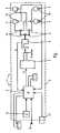
- the figure shows a brake system 1, which is installed on a towed vehicle 2 (illustrated in a dashed line), such as a semitrailer, a caravan or a trailer.
- the brake system 1 comprises a processor-controlled braking force control unit 3.
- Compound software is suitably implemented in the unit 3, which software is aimed at having wheel brakes 4 installed on wheels of the trailer 2 brake on command and in a prescribed manner.
- the control unit 3 has an input 5 for receiving a brake signal from a towing vehicle (not shown). The use of the brake signal ensures that the brake system 1 will only be activated if the towing vehicle is being braked as well.
- the brake system 1 further comprises an actuator 7 connected to the control unit 3 and the wheel brakes 4 and one (in the figure) braking force sensor 8 interposed between the actuator 7 and the wheel brakes 4, which is also connected to the braking force control unit 3, which sensor is capable of measuring the braking force currently being generated by the wheel brakes 4 and feeding the information in question (E) back to the unit 3.
- the operation of the brake system 1 is as follows. If it appears from the brake signal on the input 5 that the towing vehicle is braking, the software in the control unit 3 will deliver a feed signal C to the actuator 7.
- said feed signal C is an electric feed signal which is fed to the electro-mechanical (in that case) actuator 7.
- the actuator 7 effects a, furthermore preferably, linear, rectilinear, generally pushing or pulling movement (indicated at X with arrows pointing in opposite directions) at its output, which movement is transmitted to the respective wheel brakes 4 via the braking force sensor 8 for generating certain braking forces at said wheel brakes.
- the one (in this case) sensor 8 measures the force generated by the actuator 7 and transmitted to the wheel brakes 4, on the basis of which measurement the braking force is controlled by the unit 3 via the wheel brakes 4, in practice partially based on the G-sensor signal.
- the force measured by the sensor 8 is a measure of the braking force being generated and the relevant information (E) is fed back to the software-implemented controllable, so as to make the braking force correspond to a desired braking force by influencing (in this case) the movement X.
- the fact that the current value of the - total - braking force being generated is known has a positive effect on the stability and the reliability of the braking force control.
- a hydraulic pressure in one or more brake cylinders, or a pneumatic pressure instead of the aforesaid movement X, is influenced in such a manner that the braking force(s) measured by the sensor(s) 8 is (are) controlled to be practically equal to the desired braking force(s).
- the brake system 1 comprises one or more cable distribution elements 9 arranged between the illustrated wheel brakes 4, which are operated by means of Bowden cables, and the one braking force sensor 8. It is also possible under certain circumstances to use the hydraulic or pneumatic equivalent of said elements 9.
- said sensor is preferably (in view of the statutory regulations) of the type which passes a current of at most 15 Ampere at a nominal supply voltage of 12 V.
- the wheel brakes 4 may be hydraulic or pneumatic brakes or brakes operated by means of one or more cables. If the cables are short, any stretch in the cables will have little effect on the braking force in practice. Within the range of the control, any play or stretch in the cables is automatically compensated by the control means in the unit 3 as a result of the use of the braking force sensor(s) 8, because control eventually takes place partially based on the desired braking force and the measured braking force.
- axle load determining means 10 connected to the unit 3.
- the advantage that is obtained in this manner is that the weight of the cargo in the trailer, which presses on the respective wheel axles, is taken into account as well upon influencing the current braking force.
- several independent sensors 8 might be used to realise an individual control of the respective, possibly mutually different, required braking forces.
- brake system 1 If the brake system 1 is installed on an existing trailer 2, it can replace the overrun brake that is normally present on the trailer 2.
- braking force sensors 8 may be used. Said sensors may for example be strain gauges, which are preferred because of their simplicity and their cost price.
- the actual braking force can be determined on the basis of the pressure of the respective hydraulic fluid in the main brake cylinder, using a braking force sensor 8 configured as a pressure sensor, which communicates the pressure of the fluid to the control unit 3 in the form of an electrical feedback signal E.
- the linear (in the illustrated case) movement X at the output of the actuator 7 is then controlled in such a manner by the control unit 3 that the actual braking force is adjusted to the desired value.
- a breakaway circuit 11 connected to the unit 3 is shown, which, for safety reasons, activates the unit 3 to maximise the braking force when the towing vehicle and the trailer 3 become separated while driving.
Landscapes
- Engineering & Computer Science (AREA)
- Transportation (AREA)
- Mechanical Engineering (AREA)
- Braking Systems And Boosters (AREA)
- Regulating Braking Force (AREA)
Description
- The present invention relates to a brake system according to the preamble of claim 1.
- The invention also relates to a towed vehicle provided with such a brake system.
- Such a brake system is known from
GB-2.362.693A - The object of the present invention is to provide a brake system having a low cost price and exhibiting a higher degree of stability and precision.
- In order to accomplish that object, the brake system according to the invention has the further features of claim 1.
- The advantage of the brake system according to the invention is that the braking force sensor continuously supplies feedback information regarding the actual braking force being generated by the wheel brakes of the towed vehicle to the braking force control unit. This information is taken into account in the control strategy, which is implemented as software in the control unit, so as to precisely control the actual braking force being exerted in an advantageous manner.
- The occurrence of values of the braking forces currently being generated by the wheel brakes that lie outside the actual control range is furthermore prevented in this manner, as a result of which the control stability of the control unit is improved and the reliability of the brake system according to the invention increases. Likewise, the occurrence of undesirable leaps or variations, such as vibrations, can be reduced on the basis of the aforesaid current information, which contributes to the level of safety of the brake system according to the invention.
- Furthermore advantageous is the fact that the brake system according to the invention can be incorporated in existing overrun brake systems of towed vehicles in a relatively simple manner whilst retaining the aforesaid advantages. The well-known overrun brake that is frequently used in trailers, such as caravans, may be exchanged for the present brake system, if desired, so that problems such as undesirable activation of the brake system when driving downhill and overheating thereof will belong to the past.
- A preferred embodiment of the brake system according to the invention is characterised in that the actuator is an electro-magnetic, electro-hydraulic or electro-pneumatic actuator, in particular an actuator which effects a rectilinear movement.
- Advantageous as regards the linear electric actuator is the fact that internal losses, in particular in the form of friction, are low, so that a large part of the power supplied thereto can be effectively utilised by the wheel brakes. Furthermore, the precision of the linear outgoing mechanical movement of the actuator is high, it is easy to adjust and it has a favourable cost price.
- Where in practice a statutory limit of a nominal supply voltage of 12 V and a current of at most 15 Ampere applies as regards the total electric actuator power input of at least partially electric actuators, such an actuator nevertheless appears to be able to produce sufficient braking force on account of the limited friction. The electric actuator, which has a rotary electric motor, is even capable of briefly generating a braking power higher than the aforesaid maximum electric actuator power. The fact is that upon braking initiated by the linear - rectilinear or translatory - actuator movement, also the rotary motion already available in the electric motor is utilised. Briefly put, on account of the flywheel effect the kinetic energy of the low-play ball rotation spindle in the actuator is effectively utilised for generating additional braking power.
- Another embodiment of the brake system according to the invention is characterised in that the brake system, depending on the aforesaid type of wheel brakes, comprises one or more pneumatic, hydraulic or, if cables are provided between the cable-operated wheel brakes and said one braking force sensor, mechanical distribution means.
- Advantageously, only one braking force sensor nevertheless suffices in such cases, which sensor supplies information to the control unit about the braking force currently being generated by all the wheel brakes.
- The brake system according to the present invention will now be explained in more detail with reference to the figure below, which is a schematic view of a possible embodiment of a brake system according to the invention.
- The figure shows a brake system 1, which is installed on a towed vehicle 2 (illustrated in a dashed line), such as a semitrailer, a caravan or a trailer. The brake system 1 comprises a processor-controlled braking force control unit 3. Compound software is suitably implemented in the unit 3, which software is aimed at having
wheel brakes 4 installed on wheels of the trailer 2 brake on command and in a prescribed manner. The control unit 3 has aninput 5 for receiving a brake signal from a towing vehicle (not shown). The use of the brake signal ensures that the brake system 1 will only be activated if the towing vehicle is being braked as well. Installed on the trailer 2 is also a movement, motion or acceleration sensor, hereinafter called G-sensor 6, which delivers a signal representative of the extent of acceleration or deceleration of the trailer 2 to the control unit 3. The brake system 1 further comprises anactuator 7 connected to the control unit 3 and thewheel brakes 4 and one (in the figure)braking force sensor 8 interposed between theactuator 7 and thewheel brakes 4, which is also connected to the braking force control unit 3, which sensor is capable of measuring the braking force currently being generated by thewheel brakes 4 and feeding the information in question (E) back to the unit 3. - The operation of the brake system 1 is as follows. If it appears from the brake signal on the
input 5 that the towing vehicle is braking, the software in the control unit 3 will deliver a feed signal C to theactuator 7. As is currently preferred, said feed signal C is an electric feed signal which is fed to the electro-mechanical (in that case)actuator 7. Theactuator 7 effects a, furthermore preferably, linear, rectilinear, generally pushing or pulling movement (indicated at X with arrows pointing in opposite directions) at its output, which movement is transmitted to therespective wheel brakes 4 via thebraking force sensor 8 for generating certain braking forces at said wheel brakes. The one (in this case)sensor 8 measures the force generated by theactuator 7 and transmitted to thewheel brakes 4, on the basis of which measurement the braking force is controlled by the unit 3 via thewheel brakes 4, in practice partially based on the G-sensor signal. The force measured by thesensor 8 is a measure of the braking force being generated and the relevant information (E) is fed back to the software-implemented controllable, so as to make the braking force correspond to a desired braking force by influencing (in this case) the movement X. The fact that the current value of the - total - braking force being generated is known has a positive effect on the stability and the reliability of the braking force control. - In an alternative embodiment, equivalently to that which has been explained in the foregoing, a hydraulic pressure in one or more brake cylinders, or a pneumatic pressure, instead of the aforesaid movement X, is influenced in such a manner that the braking force(s) measured by the sensor(s) 8 is (are) controlled to be practically equal to the desired braking force(s).
- To make it possible to use only one
actuator 7 and onebraking force sensor 8, the brake system 1 comprises one or morecable distribution elements 9 arranged between the illustratedwheel brakes 4, which are operated by means of Bowden cables, and the onebraking force sensor 8. It is also possible under certain circumstances to use the hydraulic or pneumatic equivalent of saidelements 9. - In order to increase the reliability even further, several
separate actuators 7 andsensor 8 might be used. - In case an electric
linear actuator 7 is used, said sensor is preferably (in view of the statutory regulations) of the type which passes a current of at most 15 Ampere at a nominal supply voltage of 12 V. - In principle the
wheel brakes 4 may be hydraulic or pneumatic brakes or brakes operated by means of one or more cables. If the cables are short, any stretch in the cables will have little effect on the braking force in practice. Within the range of the control, any play or stretch in the cables is automatically compensated by the control means in the unit 3 as a result of the use of the braking force sensor(s) 8, because control eventually takes place partially based on the desired braking force and the measured braking force. - If desired, in view of the statutory regulations, it is also possible to use axle load determining means 10 connected to the unit 3. The advantage that is obtained in this manner is that the weight of the cargo in the trailer, which presses on the respective wheel axles, is taken into account as well upon influencing the current braking force. In the case of the expected unequal axle loads, for example caused by unevenly distributed loads, several
independent sensors 8 might be used to realise an individual control of the respective, possibly mutually different, required braking forces. - If the brake system 1 is installed on an existing trailer 2, it can replace the overrun brake that is normally present on the trailer 2.
- In principle all kinds of different types of
braking force sensors 8 may be used. Said sensors may for example be strain gauges, which are preferred because of their simplicity and their cost price. If thewheel brakes 4 are hydraulically controlled, the actual braking force can be determined on the basis of the pressure of the respective hydraulic fluid in the main brake cylinder, using abraking force sensor 8 configured as a pressure sensor, which communicates the pressure of the fluid to the control unit 3 in the form of an electrical feedback signal E. The linear (in the illustrated case) movement X at the output of theactuator 7 is then controlled in such a manner by the control unit 3 that the actual braking force is adjusted to the desired value. - In the figure a
breakaway circuit 11 connected to the unit 3 is shown, which, for safety reasons, activates the unit 3 to maximise the braking force when the towing vehicle and the trailer 3 become separated while driving.
Claims (7)
- A brake system (1) for a towed vehicle, comprising:- a braking force control unit (3) having an input (5) for a brake signal from a towing vehicle,- a sensor (6) provided on the towed vehicle which is provided with wheel brakes (4), which sensor (6) is coupled to the control unit (3),- an at least partly electric actuator (7) which is coupled to the control unit (3) and the wheel brakes (4), and- at least one braking force sensor (8) interposed between the actuator (7) and the wheel brakes (4), and coupled to the braking force control unit (3), which braking force sensor (8) supplies the control unit (3) with information (E) concerning a force, whereby the actuator (7) is fed with an electric feed signal (C) from the control unit (3) and generates at its output a pushing or pulling movement (X) that is transmitted to the braking force sensor (8), which sensor measures said force generated by the actuator (7), feeds the information (E) to the control unit (3) and transmits the movement (X) to the respective wheel brakes (4), and whereby the output of the actuator (7) is controlled by the control unit (3) in such a manner that the braking force may be adjusted, characterised in that the sensor (6) is a G-sensor, which delivers to the control unit (3) a G-sensor signal which is representative of the extent of acceleration or deceleration of the towed vehicle, that the control unit (3) controls the braking force of the towed vehicle (2) partially based on the G-sensor signal, that the braking force sensor (8) continuously supplies the information (E) concerning braking force currently being generated by the wheel brakes (4), that the control unit (3) implements the continuously supplied information in the form of feedback information (E) by software in its control strategy, and that the output of the actuator (7) is controlled by the control unit (3) in such a manner that the current braking force is adjusted to a desired value.
- A brake system (1) according to claim 1, characterised in that the actuator (7) is an electro-magnetic, electro-hydraulic or electro-pneumatic actuator, in particular an actuator (7) which effects a rectilinear movement (X).
- A brake system (1) according to any one of claims 1-2, characterised in that the actuator (7) is an electric actuator, which, controlled by the control unit (3), passes a current of at most 15 Ampere at a nominal supply voltage of 12 V.
- A brake system (1) according to any one of claims 1-3, characterised in that the wheel brakes (4) are pneumatic or hydraulic brakes or brakes operated by means of one or more cables.
- A brake system (1) according to claim 4, characterised in that the brake system (1), depending on the aforesaid type of wheel brakes (4), comprises one or more pneumatic, hydraulic or, if cables are provided between the cable-operated wheel brakes (4) and said one braking force sensor (8), mechanical distribution means (9).
- A brake system (1) according to any one of claims 1-5, characterised in that the brake system (1) comprises axle load determining means (10) coupled to the braking force control unit (3).
- A towed vehicle, such as a trailer, a caravan or the like, provided with a brake system (1) according to any one of the claims 1-6.
Priority Applications (1)
| Application Number | Priority Date | Filing Date | Title |
|---|---|---|---|
| PL09168281T PL2163446T3 (en) | 2008-09-16 | 2009-08-20 | G-sensor-controlled brake system with braking force sensor |
Applications Claiming Priority (1)
| Application Number | Priority Date | Filing Date | Title |
|---|---|---|---|
| NL2001986A NL2001986C (en) | 2008-09-16 | 2008-09-16 | G-SENSOR REGULATED BRAKE SYSTEM WITH BRAKE FORCE RECEPTION. |
Publications (2)
| Publication Number | Publication Date |
|---|---|
| EP2163446A1 EP2163446A1 (en) | 2010-03-17 |
| EP2163446B1 true EP2163446B1 (en) | 2013-02-27 |
Family
ID=40513818
Family Applications (1)
| Application Number | Title | Priority Date | Filing Date |
|---|---|---|---|
| EP09168281A Active EP2163446B1 (en) | 2008-09-16 | 2009-08-20 | G-sensor-controlled brake system with braking force sensor |
Country Status (5)
| Country | Link |
|---|---|
| EP (1) | EP2163446B1 (en) |
| ES (1) | ES2403599T3 (en) |
| NL (1) | NL2001986C (en) |
| PL (1) | PL2163446T3 (en) |
| PT (1) | PT2163446E (en) |
Cited By (8)
| Publication number | Priority date | Publication date | Assignee | Title |
|---|---|---|---|---|
| DE202014005555U1 (en) | 2014-07-08 | 2014-07-21 | Knott Gmbh | Electromechanical parking brake |
| US10670479B2 (en) | 2018-02-27 | 2020-06-02 | Methode Electronics, Inc. | Towing systems and methods using magnetic field sensing |
| US10696109B2 (en) | 2017-03-22 | 2020-06-30 | Methode Electronics Malta Ltd. | Magnetolastic based sensor assembly |
| AU2018211204B2 (en) * | 2017-08-02 | 2021-05-13 | National Chin-Yi University Of Technology | Vehicle state controlling method and vehicle state controlling system |
| US11084342B2 (en) | 2018-02-27 | 2021-08-10 | Methode Electronics, Inc. | Towing systems and methods using magnetic field sensing |
| US11135882B2 (en) | 2018-02-27 | 2021-10-05 | Methode Electronics, Inc. | Towing systems and methods using magnetic field sensing |
| US11221262B2 (en) | 2018-02-27 | 2022-01-11 | Methode Electronics, Inc. | Towing systems and methods using magnetic field sensing |
| US11491832B2 (en) | 2018-02-27 | 2022-11-08 | Methode Electronics, Inc. | Towing systems and methods using magnetic field sensing |
Families Citing this family (3)
| Publication number | Priority date | Publication date | Assignee | Title |
|---|---|---|---|---|
| CA2948779C (en) | 2015-04-22 | 2018-04-10 | Bourgault Industries Ltd. | Braking system for towed vehicles |
| NL2016703B1 (en) | 2016-04-29 | 2017-11-20 | V O F H J Busscher En Zn | Towed vehicle braking system. |
| BE1024889B1 (en) * | 2017-01-12 | 2018-08-21 | Lmj Construct Cvba | Brake system |
Family Cites Families (9)
| Publication number | Priority date | Publication date | Assignee | Title |
|---|---|---|---|---|
| DE2135222A1 (en) * | 1971-07-14 | 1973-02-01 | Kober Manpar Ag | CHASSIS FOR TRAILER VEHICLES, IN PARTICULAR CARAVANS |
| SE445821B (en) * | 1982-12-08 | 1986-07-21 | Saab Scania Ab | BRAKE SYSTEM FOR SLEPFORDON |
| GB2267134B (en) * | 1992-05-22 | 1995-10-25 | Paul Goy | Trailer vehicle |
| DE4413579A1 (en) * | 1994-04-19 | 1995-10-26 | Teves Gmbh Alfred | Electronically controllable brake actuation system |
| GB2362693A (en) * | 2000-05-23 | 2001-11-28 | Allan Arthur Askey | Braking device for a towed vehicle e.g.a caravan |
| US20020195870A1 (en) * | 2001-05-21 | 2002-12-26 | Brunson Thomas L. | Trailer braking system |
| DE202004019858U1 (en) * | 2004-12-23 | 2005-05-04 | Knott Gmbh | Electro-hydraulic brake system for overrun vehicle trailers |
| NL1031394C2 (en) * | 2006-03-17 | 2007-09-18 | Reich Kg | Brake control. |
| NL2000521C1 (en) * | 2007-03-05 | 2008-09-08 | Bart Veldhuizen B V | Binary G-sensor controlled braking system for a trailer. |
-
2008
- 2008-09-16 NL NL2001986A patent/NL2001986C/en not_active IP Right Cessation
-
2009
- 2009-08-20 PT PT91682815T patent/PT2163446E/en unknown
- 2009-08-20 ES ES09168281T patent/ES2403599T3/en active Active
- 2009-08-20 PL PL09168281T patent/PL2163446T3/en unknown
- 2009-08-20 EP EP09168281A patent/EP2163446B1/en active Active
Cited By (10)
| Publication number | Priority date | Publication date | Assignee | Title |
|---|---|---|---|---|
| DE202014005555U1 (en) | 2014-07-08 | 2014-07-21 | Knott Gmbh | Electromechanical parking brake |
| EP2965960A1 (en) | 2014-07-08 | 2016-01-13 | Knott GmbH | Electromechanical parking brake |
| US10696109B2 (en) | 2017-03-22 | 2020-06-30 | Methode Electronics Malta Ltd. | Magnetolastic based sensor assembly |
| US10940726B2 (en) | 2017-03-22 | 2021-03-09 | Methode Electronics Malta Ltd. | Magnetoelastic based sensor assembly |
| AU2018211204B2 (en) * | 2017-08-02 | 2021-05-13 | National Chin-Yi University Of Technology | Vehicle state controlling method and vehicle state controlling system |
| US10670479B2 (en) | 2018-02-27 | 2020-06-02 | Methode Electronics, Inc. | Towing systems and methods using magnetic field sensing |
| US11084342B2 (en) | 2018-02-27 | 2021-08-10 | Methode Electronics, Inc. | Towing systems and methods using magnetic field sensing |
| US11135882B2 (en) | 2018-02-27 | 2021-10-05 | Methode Electronics, Inc. | Towing systems and methods using magnetic field sensing |
| US11221262B2 (en) | 2018-02-27 | 2022-01-11 | Methode Electronics, Inc. | Towing systems and methods using magnetic field sensing |
| US11491832B2 (en) | 2018-02-27 | 2022-11-08 | Methode Electronics, Inc. | Towing systems and methods using magnetic field sensing |
Also Published As
| Publication number | Publication date |
|---|---|
| EP2163446A1 (en) | 2010-03-17 |
| PL2163446T3 (en) | 2013-07-31 |
| PT2163446E (en) | 2013-05-22 |
| ES2403599T3 (en) | 2013-05-20 |
| NL2001986C (en) | 2010-03-17 |
Similar Documents
| Publication | Publication Date | Title |
|---|---|---|
| EP2163446B1 (en) | G-sensor-controlled brake system with braking force sensor | |
| US10137875B2 (en) | Electric equipment of a vehicle, comprising an at least partly electric braking and steering device with high availability | |
| CA2935989C (en) | Method for controlling a brake device in a traction vehicle-trailer combination and brake device controlled according to said method | |
| US6666527B2 (en) | Electro-hydraulic brake actuating device for a trailer | |
| EP2480437B1 (en) | Brake system having smart actuator for braking a rail-guided vehicle | |
| KR101569957B1 (en) | Electropneumatic brake device and method for operating the same | |
| US5718486A (en) | Electropneumatic brakes system for motor vehicles | |
| US6012781A (en) | Brake control arrangement for composite vehicles | |
| KR20180039690A (en) | Brake system and method for operating a brake system | |
| US6675920B1 (en) | Towing vehicle for an aircraft | |
| EP2199166A1 (en) | A brake control system for a towed vehicle and method of calibrating the brake control system | |
| US11970146B2 (en) | Secondary brake system of a vehicle, and method for controlling it | |
| KR20180101516A (en) | Method and brake system for operating a brake system for automobiles | |
| US12005877B2 (en) | Electric over hydraulic brake system with magnetic sensor | |
| JPS63502889A (en) | Automatic adjustment device for connected vehicle brakes | |
| EP3863902B1 (en) | System and method for controlling compounding in a brake actuator | |
| CN117984966A (en) | Electromechanical brake system, brake control method and electric vehicle | |
| CN108473124B (en) | Method for controlling an electro-pneumatic parking brake device as an auxiliary brake during driving of a vehicle | |
| US20210129810A1 (en) | Trailer detection and control module | |
| CS322091A3 (en) | Fluid-pressure brake system with electrically-controlled valves | |
| US12509036B2 (en) | Electropneumatic equipment for a vehicle with an autonomous brake circuit supplied with backup pressure as a precaution | |
| US6655756B2 (en) | Fast mode release in a force generating apparatus using estimated actuator apply chamber pressure | |
| US6749271B1 (en) | Brake system for vehicles, especially commercial vehicles | |
| US7018001B2 (en) | Fast mode release in a force generating apparatus | |
| Kant | Sensotronic brake control (SBC) |
Legal Events
| Date | Code | Title | Description |
|---|---|---|---|
| PUAI | Public reference made under article 153(3) epc to a published international application that has entered the european phase |
Free format text: ORIGINAL CODE: 0009012 |
|
| 17P | Request for examination filed |
Effective date: 20090826 |
|
| AK | Designated contracting states |
Kind code of ref document: A1 Designated state(s): AT BE BG CH CY CZ DE DK EE ES FI FR GB GR HR HU IE IS IT LI LT LU LV MC MK MT NL NO PL PT RO SE SI SK SM TR |
|
| AX | Request for extension of the european patent |
Extension state: AL BA RS |
|
| 17Q | First examination report despatched |
Effective date: 20100507 |
|
| GRAP | Despatch of communication of intention to grant a patent |
Free format text: ORIGINAL CODE: EPIDOSNIGR1 |
|
| GRAS | Grant fee paid |
Free format text: ORIGINAL CODE: EPIDOSNIGR3 |
|
| GRAA | (expected) grant |
Free format text: ORIGINAL CODE: 0009210 |
|
| AK | Designated contracting states |
Kind code of ref document: B1 Designated state(s): AT BE BG CH CY CZ DE DK EE ES FI FR GB GR HR HU IE IS IT LI LT LU LV MC MK MT NL NO PL PT RO SE SI SK SM TR |
|
| REG | Reference to a national code |
Ref country code: GB Ref legal event code: FG4D |
|
| REG | Reference to a national code |
Ref country code: CH Ref legal event code: EP |
|
| REG | Reference to a national code |
Ref country code: AT Ref legal event code: REF Ref document number: 598323 Country of ref document: AT Kind code of ref document: T Effective date: 20130315 |
|
| REG | Reference to a national code |
Ref country code: IE Ref legal event code: FG4D |
|
| REG | Reference to a national code |
Ref country code: DE Ref legal event code: R096 Ref document number: 602009013594 Country of ref document: DE Effective date: 20130425 |
|
| REG | Reference to a national code |
Ref country code: CH Ref legal event code: NV Representative=s name: MEYER AND KOLLEGEN, CH |
|
| REG | Reference to a national code |
Ref country code: NL Ref legal event code: T3 |
|
| REG | Reference to a national code |
Ref country code: ES Ref legal event code: FG2A Ref document number: 2403599 Country of ref document: ES Kind code of ref document: T3 Effective date: 20130520 |
|
| REG | Reference to a national code |
Ref country code: PT Ref legal event code: SC4A Free format text: AVAILABILITY OF NATIONAL TRANSLATION Effective date: 20130515 |
|
| REG | Reference to a national code |
Ref country code: SE Ref legal event code: TRGR |
|
| REG | Reference to a national code |
Ref country code: NO Ref legal event code: T2 Effective date: 20130227 |
|
| RAP2 | Party data changed (patent owner data changed or rights of a patent transferred) |
Owner name: WAGENBOUW BOLLE B.V. |
|
| REG | Reference to a national code |
Ref country code: LT Ref legal event code: MG4D |
|
| PG25 | Lapsed in a contracting state [announced via postgrant information from national office to epo] |
Ref country code: BG Free format text: LAPSE BECAUSE OF FAILURE TO SUBMIT A TRANSLATION OF THE DESCRIPTION OR TO PAY THE FEE WITHIN THE PRESCRIBED TIME-LIMIT Effective date: 20130527 Ref country code: LT Free format text: LAPSE BECAUSE OF FAILURE TO SUBMIT A TRANSLATION OF THE DESCRIPTION OR TO PAY THE FEE WITHIN THE PRESCRIBED TIME-LIMIT Effective date: 20130227 Ref country code: IS Free format text: LAPSE BECAUSE OF FAILURE TO SUBMIT A TRANSLATION OF THE DESCRIPTION OR TO PAY THE FEE WITHIN THE PRESCRIBED TIME-LIMIT Effective date: 20130627 |
|
| REG | Reference to a national code |
Ref country code: PL Ref legal event code: T3 |
|
| PG25 | Lapsed in a contracting state [announced via postgrant information from national office to epo] |
Ref country code: FI Free format text: LAPSE BECAUSE OF FAILURE TO SUBMIT A TRANSLATION OF THE DESCRIPTION OR TO PAY THE FEE WITHIN THE PRESCRIBED TIME-LIMIT Effective date: 20130227 Ref country code: GR Free format text: LAPSE BECAUSE OF FAILURE TO SUBMIT A TRANSLATION OF THE DESCRIPTION OR TO PAY THE FEE WITHIN THE PRESCRIBED TIME-LIMIT Effective date: 20130528 Ref country code: SI Free format text: LAPSE BECAUSE OF FAILURE TO SUBMIT A TRANSLATION OF THE DESCRIPTION OR TO PAY THE FEE WITHIN THE PRESCRIBED TIME-LIMIT Effective date: 20130227 Ref country code: LV Free format text: LAPSE BECAUSE OF FAILURE TO SUBMIT A TRANSLATION OF THE DESCRIPTION OR TO PAY THE FEE WITHIN THE PRESCRIBED TIME-LIMIT Effective date: 20130227 |
|
| PG25 | Lapsed in a contracting state [announced via postgrant information from national office to epo] |
Ref country code: HR Free format text: LAPSE BECAUSE OF FAILURE TO SUBMIT A TRANSLATION OF THE DESCRIPTION OR TO PAY THE FEE WITHIN THE PRESCRIBED TIME-LIMIT Effective date: 20130227 |
|
| PG25 | Lapsed in a contracting state [announced via postgrant information from national office to epo] |
Ref country code: EE Free format text: LAPSE BECAUSE OF FAILURE TO SUBMIT A TRANSLATION OF THE DESCRIPTION OR TO PAY THE FEE WITHIN THE PRESCRIBED TIME-LIMIT Effective date: 20130227 Ref country code: CZ Free format text: LAPSE BECAUSE OF FAILURE TO SUBMIT A TRANSLATION OF THE DESCRIPTION OR TO PAY THE FEE WITHIN THE PRESCRIBED TIME-LIMIT Effective date: 20130227 Ref country code: RO Free format text: LAPSE BECAUSE OF FAILURE TO SUBMIT A TRANSLATION OF THE DESCRIPTION OR TO PAY THE FEE WITHIN THE PRESCRIBED TIME-LIMIT Effective date: 20130227 Ref country code: SK Free format text: LAPSE BECAUSE OF FAILURE TO SUBMIT A TRANSLATION OF THE DESCRIPTION OR TO PAY THE FEE WITHIN THE PRESCRIBED TIME-LIMIT Effective date: 20130227 Ref country code: DK Free format text: LAPSE BECAUSE OF FAILURE TO SUBMIT A TRANSLATION OF THE DESCRIPTION OR TO PAY THE FEE WITHIN THE PRESCRIBED TIME-LIMIT Effective date: 20130227 |
|
| PG25 | Lapsed in a contracting state [announced via postgrant information from national office to epo] |
Ref country code: CY Free format text: LAPSE BECAUSE OF FAILURE TO SUBMIT A TRANSLATION OF THE DESCRIPTION OR TO PAY THE FEE WITHIN THE PRESCRIBED TIME-LIMIT Effective date: 20130227 |
|
| PG25 | Lapsed in a contracting state [announced via postgrant information from national office to epo] |
Ref country code: IT Free format text: LAPSE BECAUSE OF FAILURE TO SUBMIT A TRANSLATION OF THE DESCRIPTION OR TO PAY THE FEE WITHIN THE PRESCRIBED TIME-LIMIT Effective date: 20130227 |
|
| PLBE | No opposition filed within time limit |
Free format text: ORIGINAL CODE: 0009261 |
|
| STAA | Information on the status of an ep patent application or granted ep patent |
Free format text: STATUS: NO OPPOSITION FILED WITHIN TIME LIMIT |
|
| 26N | No opposition filed |
Effective date: 20131128 |
|
| REG | Reference to a national code |
Ref country code: DE Ref legal event code: R097 Ref document number: 602009013594 Country of ref document: DE Effective date: 20131128 |
|
| PG25 | Lapsed in a contracting state [announced via postgrant information from national office to epo] |
Ref country code: MC Free format text: LAPSE BECAUSE OF FAILURE TO SUBMIT A TRANSLATION OF THE DESCRIPTION OR TO PAY THE FEE WITHIN THE PRESCRIBED TIME-LIMIT Effective date: 20130227 |
|
| REG | Reference to a national code |
Ref country code: IE Ref legal event code: MM4A |
|
| PG25 | Lapsed in a contracting state [announced via postgrant information from national office to epo] |
Ref country code: IE Free format text: LAPSE BECAUSE OF NON-PAYMENT OF DUE FEES Effective date: 20130820 |
|
| PG25 | Lapsed in a contracting state [announced via postgrant information from national office to epo] |
Ref country code: SM Free format text: LAPSE BECAUSE OF FAILURE TO SUBMIT A TRANSLATION OF THE DESCRIPTION OR TO PAY THE FEE WITHIN THE PRESCRIBED TIME-LIMIT Effective date: 20130227 |
|
| PG25 | Lapsed in a contracting state [announced via postgrant information from national office to epo] |
Ref country code: MT Free format text: LAPSE BECAUSE OF FAILURE TO SUBMIT A TRANSLATION OF THE DESCRIPTION OR TO PAY THE FEE WITHIN THE PRESCRIBED TIME-LIMIT Effective date: 20130227 Ref country code: TR Free format text: LAPSE BECAUSE OF FAILURE TO SUBMIT A TRANSLATION OF THE DESCRIPTION OR TO PAY THE FEE WITHIN THE PRESCRIBED TIME-LIMIT Effective date: 20130227 |
|
| PG25 | Lapsed in a contracting state [announced via postgrant information from national office to epo] |
Ref country code: HU Free format text: LAPSE BECAUSE OF FAILURE TO SUBMIT A TRANSLATION OF THE DESCRIPTION OR TO PAY THE FEE WITHIN THE PRESCRIBED TIME-LIMIT; INVALID AB INITIO Effective date: 20090820 Ref country code: LU Free format text: LAPSE BECAUSE OF NON-PAYMENT OF DUE FEES Effective date: 20130820 Ref country code: MK Free format text: LAPSE BECAUSE OF FAILURE TO SUBMIT A TRANSLATION OF THE DESCRIPTION OR TO PAY THE FEE WITHIN THE PRESCRIBED TIME-LIMIT Effective date: 20130227 |
|
| REG | Reference to a national code |
Ref country code: FR Ref legal event code: PLFP Year of fee payment: 8 |
|
| REG | Reference to a national code |
Ref country code: FR Ref legal event code: PLFP Year of fee payment: 9 |
|
| REG | Reference to a national code |
Ref country code: FR Ref legal event code: PLFP Year of fee payment: 10 |
|
| P01 | Opt-out of the competence of the unified patent court (upc) registered |
Effective date: 20230513 |
|
| PGFP | Annual fee paid to national office [announced via postgrant information from national office to epo] |
Ref country code: PT Payment date: 20240801 Year of fee payment: 16 |
|
| PGFP | Annual fee paid to national office [announced via postgrant information from national office to epo] |
Ref country code: BE Payment date: 20240827 Year of fee payment: 16 |
|
| PGFP | Annual fee paid to national office [announced via postgrant information from national office to epo] |
Ref country code: ES Payment date: 20240902 Year of fee payment: 16 Ref country code: CH Payment date: 20240903 Year of fee payment: 16 |
|
| PGFP | Annual fee paid to national office [announced via postgrant information from national office to epo] |
Ref country code: NO Payment date: 20240828 Year of fee payment: 16 Ref country code: SE Payment date: 20240827 Year of fee payment: 16 |
|
| PGFP | Annual fee paid to national office [announced via postgrant information from national office to epo] |
Ref country code: NL Payment date: 20250826 Year of fee payment: 17 |
|
| PGFP | Annual fee paid to national office [announced via postgrant information from national office to epo] |
Ref country code: DE Payment date: 20250827 Year of fee payment: 17 |
|
| PGFP | Annual fee paid to national office [announced via postgrant information from national office to epo] |
Ref country code: GB Payment date: 20250827 Year of fee payment: 17 |
|
| PGFP | Annual fee paid to national office [announced via postgrant information from national office to epo] |
Ref country code: FR Payment date: 20250825 Year of fee payment: 17 Ref country code: AT Payment date: 20250827 Year of fee payment: 17 |
|
| PGFP | Annual fee paid to national office [announced via postgrant information from national office to epo] |
Ref country code: PL Payment date: 20250731 Year of fee payment: 17 |
|
| REG | Reference to a national code |
Ref country code: CH Ref legal event code: H13 Free format text: ST27 STATUS EVENT CODE: U-0-0-H10-H13 (AS PROVIDED BY THE NATIONAL OFFICE) Effective date: 20260324 |
|
| PG25 | Lapsed in a contracting state [announced via postgrant information from national office to epo] |
Ref country code: NO Free format text: LAPSE BECAUSE OF NON-PAYMENT OF DUE FEES Effective date: 20250831 |
|
| PG25 | Lapsed in a contracting state [announced via postgrant information from national office to epo] |
Ref country code: PT Free format text: LAPSE BECAUSE OF NON-PAYMENT OF DUE FEES Effective date: 20260220 Ref country code: CH Free format text: LAPSE BECAUSE OF NON-PAYMENT OF DUE FEES Effective date: 20250831 |