EP2181023B1 - Optischer koppelkörper - Google Patents
Optischer koppelkörper Download PDFInfo
- Publication number
- EP2181023B1 EP2181023B1 EP08787386.5A EP08787386A EP2181023B1 EP 2181023 B1 EP2181023 B1 EP 2181023B1 EP 08787386 A EP08787386 A EP 08787386A EP 2181023 B1 EP2181023 B1 EP 2181023B1
- Authority
- EP
- European Patent Office
- Prior art keywords
- coupling
- optoelectronic
- facility
- element according
- retaining frame
- Prior art date
- Legal status (The legal status is an assumption and is not a legal conclusion. Google has not performed a legal analysis and makes no representation as to the accuracy of the status listed.)
- Active
Links
Images
Classifications
-
- B—PERFORMING OPERATIONS; TRANSPORTING
- B60—VEHICLES IN GENERAL
- B60S—SERVICING, CLEANING, REPAIRING, SUPPORTING, LIFTING, OR MANOEUVRING OF VEHICLES, NOT OTHERWISE PROVIDED FOR
- B60S1/00—Cleaning of vehicles
- B60S1/02—Cleaning windscreens, windows or optical devices
- B60S1/04—Wipers or the like, e.g. scrapers
- B60S1/06—Wipers or the like, e.g. scrapers characterised by the drive
- B60S1/08—Wipers or the like, e.g. scrapers characterised by the drive electrically driven
- B60S1/0818—Wipers or the like, e.g. scrapers characterised by the drive electrically driven including control systems responsive to external conditions, e.g. by detection of moisture, dirt or the like
- B60S1/0822—Wipers or the like, e.g. scrapers characterised by the drive electrically driven including control systems responsive to external conditions, e.g. by detection of moisture, dirt or the like characterized by the arrangement or type of detection means
- B60S1/0874—Wipers or the like, e.g. scrapers characterised by the drive electrically driven including control systems responsive to external conditions, e.g. by detection of moisture, dirt or the like characterized by the arrangement or type of detection means characterized by the position of the sensor on the windshield
- B60S1/0881—Wipers or the like, e.g. scrapers characterised by the drive electrically driven including control systems responsive to external conditions, e.g. by detection of moisture, dirt or the like characterized by the arrangement or type of detection means characterized by the position of the sensor on the windshield characterized by the attachment means on the windshield
-
- B—PERFORMING OPERATIONS; TRANSPORTING
- B60—VEHICLES IN GENERAL
- B60S—SERVICING, CLEANING, REPAIRING, SUPPORTING, LIFTING, OR MANOEUVRING OF VEHICLES, NOT OTHERWISE PROVIDED FOR
- B60S1/00—Cleaning of vehicles
- B60S1/02—Cleaning windscreens, windows or optical devices
- B60S1/04—Wipers or the like, e.g. scrapers
- B60S1/06—Wipers or the like, e.g. scrapers characterised by the drive
- B60S1/08—Wipers or the like, e.g. scrapers characterised by the drive electrically driven
- B60S1/0818—Wipers or the like, e.g. scrapers characterised by the drive electrically driven including control systems responsive to external conditions, e.g. by detection of moisture, dirt or the like
- B60S1/0822—Wipers or the like, e.g. scrapers characterised by the drive electrically driven including control systems responsive to external conditions, e.g. by detection of moisture, dirt or the like characterized by the arrangement or type of detection means
- B60S1/0874—Wipers or the like, e.g. scrapers characterised by the drive electrically driven including control systems responsive to external conditions, e.g. by detection of moisture, dirt or the like characterized by the arrangement or type of detection means characterized by the position of the sensor on the windshield
- B60S1/0888—Wipers or the like, e.g. scrapers characterised by the drive electrically driven including control systems responsive to external conditions, e.g. by detection of moisture, dirt or the like characterized by the arrangement or type of detection means characterized by the position of the sensor on the windshield characterized by the attachment of the elements in a unit
Definitions
- the invention relates to an optical coupling body for coupling an optoelectronic device to a vehicle window, comprising a transparent coupling medium of a silicone material, which is surrounded by a peripheral edge of a holding frame, wherein the holding frame as a separate, not connected to a housing part of the optoelectronic device manufactured item is, and wherein the holding frame can be coupled to a part of the optoelectronic device, whereby at the same time the coupling body comes to an optically active surface of the optoelectronic device for conditioning.
- a coupling body is known in which the holding frame is formed by an outer surface of the housing of an optoelectronic device, on which a peripheral edge is formed.
- the coupling medium of such a coupling body is preferably made of a gel-like highly transparent silicone material and serves for the optical To allow coupling of the optical body to the vehicle window. Due to its low-viscosity consistency, a gel-like coupling medium adapts well to the surfaces of the components to be coupled to each other.
- the coupling body is designed to be self-supporting by a selection of the silicone material used which is adapted to the size and design of the holding frame and is thus connected to the holding frame only at its edge surfaces.
- a large-area support of the optically effective surfaces of the coupling body is advantageously not required.
- the bonding of the silicone material to the holding frame can be effected by a suitable shaping of the inner edge surface in a form-fitting manner, or alternatively or additionally, by means of chemical bonding forces.
- the latter can be achieved for example by a surface treatment of the inner edge surface, such as by a corona treatment, by dissolving the surface by a solvent or by applying an adhesive material.
- the coupling body is provided with a retracted into the holding frame dimensionally stable support surface which is rigid or foil-like and which achieves additional mechanical stabilization of the coupling medium without the coupling medium must be supported on its outer end faces.
- the coupling body forms a preassembled unit by the coupling medium fixed within the holding frame, which unit is easily replaceable in the case of service.
- the holding frame has holding elements, with which it is fixed on the optical body, whereby the coupling body is clearly positioned to the optical body.
- the free surfaces of the coupling medium may advantageously be provided with a protective film prior to assembly with the optoelectronic device. If the coupling body delivered as a service part to a workshop, the coupling medium can be used as Bermmtik in addition to the top and bottom a z. B. waxed protective film, which makes no intimate connection with the coupling medium and thus is easy to remove before mounting.
- the protective film may preferably be releasably secured to the support frame to prevent the lateral ingress of contamination until assembly.
- the protective film may also be printed for identification purposes.
- a plurality of units may be separably connected by the protective film to a packaging unit.
- the support frame may additionally have elastic sealing elements as a third component.
- To the support frame may, in addition to the fasteners, if necessary, still positioning, sealing, coding or labeling belong.
- the coupling medium can be embodied in one component or, alternatively, can be composed of several layers, each consisting of silicone materials with different physical properties.
- silicone gels As a particularly advantageous materials for the formation of the coupling medium silicone gels have proven that z. B. under the trade name Silgel 612 are available, as these are characterized by a chemically largely inert behavior and physiological safety. In addition, they have extremely favorable optical properties, in particular a high transparency, as well as refractive indices, which are similar to those of optical glasses. Further advantageously usable silicone materials are available under the names BAYER LSR 2003 with 5 Shore A or Wacker LR 3070/10 with 10 Shore A.
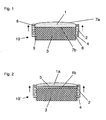
- the Figures 1 and 2 each show a coupling body (10, 10 ') according to the invention, which is connected to an optical body (3).
- the optic body (3) is part of an optoelectronic device, not shown in the drawing, in a motor vehicle.
- the optical body (3) is that optical component of the optoelectronic device, which is optically coupled by the coupling body (10, 10 ') to the vehicle window, also not shown.
- the optical body (3) can be embodied, for example, as a camera lens, a prism or a light-guiding body and accordingly consists of a transparent and preferably solid material, in particular of a glass or plastic.
- the coupling body (10, 10 ') consists in each case of a holding frame (2) which forms a ring-shaped or frame-shaped boundary for a coupling medium (1, 1a, 1b) encompassed by the holding frame (2).
- the coupling medium (1, 1a, 1b) consists of a silicone material, preferably of a silicone gel or of an injection-molded low-viscosity silicone rubber (liquid silicone rubber).
- the silicone material is chosen with regard to its viscosity so that the coupling medium (1) are kept dimensionally stable solely by the ring-shaped or frame-shaped holding frame (2).
- Stable in this case means that the coupling medium (1, 1a, 1b) remains stable within the by the holding frame (2) spanned, cylindrical or prismatic volume and without an additional support on its faces, under the action of gravity neither from the Holding frame (2) bulges appreciably out of the holding frame (2) falls out or flows out.
- this does not exclude that for additional stabilization of the coupling medium (1, 1a, 1b) such additional support on the end faces can certainly be provided.
- a suitable silicone material is, due to the different viscosities of different silicones, especially on the dimensions, ie the shape and size of the proposed coupling body (10, 10 ') dependent. Since the dimensioning of the coupling body (10, 10 ') in turn strongly depends on the intended application, no further determination has been made here for the choice of material. Given the variety of available silicone materials with different viscosities but it prepares no difficulty to select a suitable material for the particular application, where, in addition to the for a Coupling medium typical properties such as high transparency and low scattering effect, only on a suitable refractive index of the coupling medium (1, 1a, 1b) for the intended application is pay attention.
- the coupling medium (1) is held solely on the inner edge surface of the holding frame (2).
- the inner edge surface has for this purpose an integrally formed contour (6), in which in the FIG. 1 shown holding frame (2) is formed by a circumferential along the inner edge surface groove with which the coupling medium (1) can form a positive connection, here in the form of a tongue and groove connection.
- the inner edge surface of the holding frame (2) can of course also any other contour, such as a labyrinth contour; which is suitable for holding the coupling medium (1) in a form-fitting manner.
- the coupling medium (1) can also be connected by adhesive bonding to the inner edge surface of the holder frame (2).
- a support surface (5) In the in the FIG. 2 illustrated embodiment of a coupling body (10 ') is retracted for mechanical stabilization in the interior of the holding frame (2) a support surface (5).
- the coupling medium (1a, 1b) is here designed in two parts and arranged on both sides of the support surface (5).
- the support surface (5) should also have a suitably selected refractive index, be highly transparent and have only a small scattering effect.
- the carrier surface (5) offers a simple possibility, if necessary, to use different silicone materials on both sides of the carrier surface (5) to form the coupling medium (1a, 1b), which may be advantageous depending on the application.
- the support surface may also form an optical filter.
- the support surface can have both transparent and opaque partial surfaces and thus act as a scattered light diaphragm.
- the support surface (5) as in the FIG. 2 illustrated, extend over the entire by the holding frame (2) spanned surface, so that the support surface (5) must be formed completely or at least in functionally relevant areas optically transparent.
- the carrier surface can also be designed as a surface running around the inner edge surface of the holding frame and connected to the holding frame, for example in the form of a circular ring which has an opening in the middle region which is correspondingly optically transparent. The breakthrough is completely filled by the applied to both sides of the support surface coupling media.
- the coupling body (10, 10 ') consisting of a holding frame (2) and a held-coupled coupling medium (1, 1a, 1b), can be manufactured and sold as a preassembled spare part.
- a coupling body (10, 10 ') formed in this way can be easily represented by detachable connecting elements (8), here exemplified as a latching device, which is connected to the holding frame (2) via molded-on retaining arms (4) on a holder (9) on the Optic body (3) are attached.
- detachable connecting elements (8) here exemplified as a latching device, which is connected to the holding frame (2) via molded-on retaining arms (4) on a holder (9) on the Optic body (3) are attached.
- releasable connection elements of the support frame (2) beyond with a here also not shown holding device are connected to the vehicle window.
- a particular advantage of the exchangeable coupling body is that thereby specific service work, which relate to an optoelectronic device provided therewith, can be performed significantly cheaper. Namely, if a coupled by means of a coupling body to a vehicle window optoelectronic device separated from the vehicle window, which is required, for example, when the vehicle window replaced or work on the optoelectronic device are required, which is adhering to the vehicle window and the optic body coupling medium is often destroyed. Since hitherto the application of a new coupling medium to the optoelectronic device required a considerable effort and was often not feasible by service workshops, the expensive optoelectronic device had to be completely replaced in these cases.
- the replaceable coupling body according to the invention now allows a cost-effective replacement, in which, after removing the remains of the destroyed coupling medium from the vehicle window and the optical body (3), simply the holding frame (2) of the coupling body to be replaced (10, 10 ') of the optical body (3) dissolved and a new optical coupling body (10, 10 ') on the optical body (3), is snapped. A complete replacement of the optoelectronic device is therefore no longer necessary.
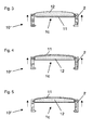
- FIGS. 3 to 5 Three further advantageous embodiments of a coupling body (10 ") are shown here: The illustration of an optic body was omitted here: The arrows shown laterally next to the coupling body (10") each point in the direction of a vehicle window (not shown) and thus illustrate the mounting direction.
- the coupling body (10 ") is shown here essentially as it is manufactured and available as a single part.
- the coupling body (10 ) in these three embodiments has no retracted carrier frame made of a relatively rigid material, these are in the FIG. 1 illustrated embodiments comparable.
- the coupling medium (1 c) here has a multilayer structure of two different silicone materials (11, 12), wherein in each case a first silicone material (11) partially or completely surrounds a second silicone material (12).
- the first silicone material (11) has a higher viscosity than the second silicone material (12), whereby the coupling body (10 ") consisting of two silicone materials (11, 12) is additionally stabilized.
- the layered structure of the coupling body (10 ") allows a particularly accurate adaptation of the optical and mechanical properties to the requirements of the particular application.
- FIG. 3 forms the first silicone material (11) from a kind of tub, which establishes the mechanical connection to the holding frame (2).
- the trough facing the vehicle window, this trough is filled with the second silicone material (12).
- FIG. 4 A reverse arrangement of the tub is in the FIG. 4 shown; the trough filled with the second silicone material (12) is opened here in the direction of the optic body not shown here.
- the coupling body (10 ") is formed by the second silicone material (12) completely enclosing the first silicone material (11).
- a silicone gel can be used for the low-viscosity first silicone material (11) and an injection-moldable silicone rubber (liquid silicone rubber) can be used for the highly viscous second silicone material (12).
- an injection-moldable silicone rubber liquid silicone rubber
Landscapes
- Engineering & Computer Science (AREA)
- Automation & Control Theory (AREA)
- Mechanical Engineering (AREA)
- Mounting And Adjusting Of Optical Elements (AREA)
Description
- Die Erfindung betrifft einen optischen Koppelkörper zur Ankopplung einer optoelektronischen Vorrichtung an eine Fahrzeugscheibe, mit einem transparenten Koppelmedium aus einem Silikonmaterial, welches von einem umlaufenden Rand eines Halterahmens umfasst ist, wobei der Halterahmen als ein separates, nicht mit einem Gehäuseteil der optoelektronischen Vorrichtung verbundenes Einzelteil gefertigt ist, und wobei der Halterahmen an einem Teil der optoelektronischen Vorrichtung ankoppelbar ist, wodurch zugleich der Koppelkörper an einer optisch wirksamen Fläche der optoelektronischen Vorrichtung zur Anlage kommt.
- Ein derartiger Koppelkörper ist in der deutschen Offenlegungsschrift
DE 10 2006 059 554 A1 beschrieben. - Aus der
DE 101 19 219 A1 ist ein Koppelkörper bekannt, bei dem der Halterahmen durch eine äußere Oberfläche des Gehäuses einer optoelektronischen Vorrichtung gebildet ist, an der ein umlaufender Rand angeformt ist. - Das Koppelmedium eines derartigen Koppelkörpers besteht vorzugsweise aus einem gelartigen hochtransparenten Silikonmaterial und dient zur optischen Ankopplung der Optikkörper an die Fahrzeugscheibe zu ermöglichen. Aufgrund seiner niederviskosen Konsistenz passt sich ein gelartiges Koppelmedium gut an die Oberflächen der aneinander zu koppelnden Komponenten an.
- Vorbekannte Koppelkörper haben allerdings den Nachteil, dass das Koppelmedium eine innige Verbindung mit der Fahrzeugscheibe und ebenso mit dem Optikkörper der optoelektronischen Vorrichtung eingeht, welche das Koppelmedium an die Fahrzeugscheibe anpresst. Dies ist nachteilig, wenn entweder die Fahrzeugscheibe oder die optoelektronische Vorrichtung ausgetauscht werden soll. In einem solchen Servicefall wird beim Entfernen der optoelektronischen Vorrichtung von der Fahrzeugscheibe das gelartige Koppelmedium zerstört, wonach die an der Fahrzeugscheibe verbleibenden Reste des Koppelmediums von der Fahrzeugscheibe entfernt werden müssen. Da beim Zerreißen des Koppelmediums mitunter sehr kleine Reste entstehen, die zudem sehr fest an der Fahrzeugscheibe anhaften, ist die Rückstandsbeseitigung mit einem hohen Aufwand verbunden.
- Darüber hinaus verbleiben in gleicher Weise Rückstände des Koppelmediums am Optikkörper, der ebenfalls auf aufwändige Weise von diesen Rückständen befreit werden muss. Alternativ dazu kann die optoelektronische Vorrichtung auch vollständig ausgetauscht werden, was aber sehr kostenaufwändig ist äußerste Sorgfalt und ist damit nicht immer unproblematisch, zumindest aber aufwändig.
- Es stellte sich somit die Aufgabe, einen Koppelkörper zu schaffen, der bei der Montage besonders einfach zu handhaben ist und der besonders im Servicefall auf einfache und kostengünstige Weise austauschbar ist.
- Diese Aufgabe wird erfindungsgemäß jeweils durch die kennzeichnenden Merkmale der Ansprüche 1 bis 3 gelöst.
- In der ersten erfindungsgemäßen Ausgestaltung ist der Koppelkörper durch eine an die Größe und Ausführung des Halterahmens angepasste Auswahl des verwendeten Silikonmaterials selbsttragend ausgebildet und wird damit mit dem Halterahmen nur an dessen Randflächen verbunden. Eine großflächige Abstützung der optisch wirksamen Oberflächen des Koppelkörpers ist vorteilhafterweise nicht erforderlich.
- Die Anbindung des Silikonmaterials an den Halterahmen kann durch eine geeignete Formgebung der inneren Randfläche formschlüssig, oder aber, alternativ oder zusätzlich, mittels chemischer Bindungskräfte erfolgen. Letzteres kann beispielsweise durch eine Oberflächenbehandlung der inneren Randfläche erreicht werden, etwa durch eine Coronabehandlung, durch Anlösen der Oberfläche durch ein Lösungsmittel oder auch durch Aufbringen eines Klebematerials.
- In der zweiten erfindungsgemäßen Ausgestaltung ist der Koppelkörper mit einer in den Halterahmen eingezogenen formstabilen Trägerfläche versehen, die starr oder folienartig ausgebildet ist und die eine zusätzliche mechanische Stabilisierung des Koppelmediums erreicht, ohne dass das Koppelmedium an seinen äußeren Stirnflächen abgestützt werden muss.
- Vorteilhaft ist es, dass der Koppelkörper durch das innerhalb des Halterahmens fixierte Koppelmedium eine vormontierte Einheit bildet, die im Servicefall leicht austauschbar ist.
- Mit Hilfe dieses Halterahmens kann man einerseits den Koppelkörper ohne ihn direkt anfassen zu müssen auf den Optikkörper montieren und andererseits im Servicefall auch wieder leicht vom Optikkörper und von der Scheibe entfernen.
- Der Halterahmen weist Halteelemente auf, mit denen er auf dem Optikkörper fixiert wird, wodurch der Koppelkörper eindeutig zum Optikkörper positionierbar ist.
- Weitere vorteilhafte Ausgestaltungen und Weiterbildungen sind in den abhängigen Ansprüchen genannt.
- Die freien Oberflächen des Koppelmediums können vorteilhaft vor dem Zusammenfügen mit der optoelektronischen Vorrichtung mit jeweils einer Schutzfolie versehen sein. Wird der Koppelkörper als Serviceteil an eine Werkstatt geliefert, kann das Koppelmediums als Berührschutz zusätzlich auf der Ober- und der Unterseite eine z. B. gewachste Schutzfolie aufweisen, die keine innige Verbindung mit dem Koppelmedium eingeht und somit leicht vor der Montage zu entfernen ist.
- Die Schutzfolie kann vorzugsweise am Halterahmen lösbar befestigt sein, um bis zur Montage das seitliche Eindringen von Kontamination zu verhindern. Die Schutzfolie kann überdies zu Kennzeichnungszwecken bedruckt sein. Außerdem können mehrere Einheiten durch die Schutzfolie trennbar zu einer Verpackungseinheit verbunden sein.
- Der Halterahmen kann zusätzlich noch elastische Dichtelemente als dritte Komponente aufweisen. Zu dem Halterahmen können außer den Befestigungselementen bedarfsweise noch Positionierungs-, Dichtungs-, Kodierungs- oder Kennzeichnungselemente gehören.
- Das Koppelmedium kann einkomponentig ausgeführt sein oder alternativ aus mehreren Schichten aufgebaut sein, die jeweils aus Silikonmaterialien mit unterschiedlichen physikalischen Eigenschaften bestehen.
- Als besonders vorteilhafte Materialien zur Ausbildung des Koppelmediums haben sich Silikongele erwiesen, die z. B. unter der Handelsbezeichnung Silgel 612 erhältlich sind, da sich diese durch ein chemisch weitgehend inertes Verhalten und physiologische Unbedenklichkeit auszeichnen. Außerdem weisen sie äußerst günstige optische Eigenschaften auf, insbesondere eine hohe Transparenz, sowie Brechungsindizes, die denen optischer Gläser ähnlich sind. Weitere vorteilhaft verwendbare Silikonmaterialien sind unter den Bezeichnungen BAYER LSR 2003 mit 5 Shore A oder Wacker LR 3070/10 mit 10 Shore A erhältlich.
- Im folgenden wird ein Ausführungsbeispiel der Erfindung anhand der Zeichnung dargestellt und näher erläutert. Es zeigen, jeweils in einer schematischen Schnittdarstellung:
- Figur 1
- eine erste Ausführungsform eines mit einem Optikkörper verbundenen Koppelkörpers,
- Figur 2
- eine zweite Ausführungsform eines mit einem Optikkörper verbundenen Koppelkörpers,
- Figuren 3 -5
- jeweils eine weitere Ausführungsvariante eines Koppelkörpers.
- Die
Figuren 1 und 2 zeigen jeweils einen erfindungsgemäßen Koppelkörper (10, 10'), der mit einem Optikkörper (3) verbunden ist. Der Optikkörper (3) ist Bestandteil einer in der Zeichnung nicht dargestellten optoelektronischen Vorrichtung in einem Kraftfahrzeug. - Der Optikkörper (3) ist diejenige optische Komponente der optoelektronischen Vorrichtung, die durch den Koppelkörper (10, 10') optisch an die ebenfalls nicht dargestellte Fahrzeugscheibe angekoppelt wird. Der Optikkörper (3) kann beispielsweise als eine Kameralinse, ein Prisma oder ein Lichtleitkörper ausgeführt sein und besteht dementsprechend aus einem transparenten und vorzugsweise festen Material, und zwar insbesondere aus einem Glas oder Kunststoff.
- Der Koppelkörper (10, 10') besteht jeweils aus einem Halterahmen (2), der eine ring- oder rahmenförmige Berandung für ein vom Halterahmen (2) umfasstes Koppelmedium (1, 1a, 1b) ausbildet.
- Das Koppelmedium (1, 1a, 1b) besteht aus einem Silikonmaterial und zwar vorzugsweise aus einem Silikongel oder aus einem spritzgegossenen niedrigviskosen Silikonkautschuk (liquid silicone rubber). Insbesondere bei der Ausführungsform gemäss der
Figur 1 ist das Silikonmaterial hinsichtlich seiner Viskosität so gewählt, dass das Koppelmedium (1) allein von dem ring- oder rahmenförmigen Halterahmen (2) formstabil gehalten werden. - Formstabil bedeutet hierbei, dass das Koppelmedium (1, 1a, 1b) stabil innerhalb des durch den Halterahmen (2) aufgespannten, zylinder- oder prismenförmigen Volumens verbleibt und auch ohne eine zusätzliche Abstützung an seinen Stirnflächen, sich unter der Wirkung der Schwerkraft weder aus dem Halterahmen (2) nennenswert herauswölbt noch aus dem Halterahmen (2) herausfällt oder herausfließt. Dies schließt selbstverständlich nicht aus, dass zur zusätzlichen Stabilisierung des Koppelmediums (1, 1a, 1b) eine derartige zusätzliche Abstützung an den Stirnflächen durchaus vorgesehen sein kann.
- Die Auswahl eines geeigneten Silikonmaterials ist dabei, bedingt durch die unterschiedlichen Viskositäten verschiedener Silikone, besonders von der Dimensionierung, also von Form und Größe des vorgesehenen Koppelkörpers (10, 10') abhängig. Da die Dimensionierung des Koppelkörpers (10, 10') wiederum stark von der vorgesehenen Anwendung abhängt, ist hier keine weitergehende Festlegung für die Materialwahl getroffen worden. Angesichts der Vielzahl von verfügbaren Silikonmaterialien mit unterschiedlichen Viskositäten bereitet es aber keine Schwierigkeiten, ein für den jeweiligen Anwendungsfall geeignetes Material auszuwählen, wobei, neben den für ein Koppelmedium typischen Eigenschaften wie hohe Transparenz und geringe Streuwirkung, lediglich noch auf einen geeigneten Brechungsindex des Koppelmediums (1, 1a, 1b) für den vorgesehenen Anwendungsfall zu achten ist.
- Bei dem in der
Figur 1 dargestellten Ausführungsbeispiels eines Koppelkörpers (10) ist das Koppelmedium (1) allein an der inneren Randfläche des Halterahmens (2) gehalten. Die innere Randfläche weist dazu eine angeformte Kontur (6) auf, die bei dem in derFigur 1 dargestellten Halterahmen (2) durch eine entlang der inneren Randfläche umlaufende Nut gebildet ist, mit der das Koppelmedium (1) eine formschlüssige Verbindung, hier in Form einer Nut-Feder-Verbindung, eingehen kann. - Die innere Randfläche des Halterahmens (2) kann selbstverständlich auch eine beliebige andere Kontur, etwa eine Labyrinthkontur; aufweisen, die geeignet ist das Koppelmedium (1) formschlüssig zu halten. Darüber hinaus oder alternativ kann das Koppelmedium (1) auch durch eine Verklebung mit der inneren Randfläche des Halterrahmens (2) verbunden sein.
- In dem in der
Figur 2 dargestellten Ausführungsbeispiel eines Koppelkörpers (10') ist zur mechanischen Stabilisierung in das Innere des Halterahmens (2) eine Trägerfläche (5) eingezogen. Das Koppelmedium (1a, 1b) ist hier entsprechend zweiteilig ausgeführt und zu beiden Seiten der Trägerfläche (5) angeordnet. Wie das Koppelmedium (1a, 1b) sollte auch die Trägerfläche (5) einen geeignet gewählten Brechungsindex aufweisen, hochtransparent sein und nur eine geringe Streuwirkung haben. Darüber hinaus bietet die Trägerfläche (5) eine einfache Möglichkeit, bedarfsweise auf beiden Seiten der Trägerfläche (5) zur Ausbildung des Koppelmediums (1a, 1b) unterschiedliche Silikonmaterialien zu verwenden, was je nach Anwendungsfall vorteilhaft sein kann. - Die Trägerfläche kann darüber hinaus ein optisches Filter ausbilden. Insbesondere kann die Trägerfläche sowohl transparente als auch lichtundurchlässige Teilflächen aufweisen und dergestalt als Streulichtblende wirken.
- Die Trägerfläche (5) kann, wie in der
Figur 2 dargestellt, sich über die gesamte durch den Halterahmen (2) aufgespannte Fläche erstrecken, so dass die Trägerfläche (5) vollständig oder zumindest in funktionsrelevanten Bereichen optisch transparent ausgebildet sein muss. - Die Trägerfläche kann alternativ auch als ein entlang der inneren Randfläche des Halterahmens umlaufende und mit dem Halterahmen verbundene Fläche, etwa in Form eines Kreisrings ausgebildet sein, die im mittleren Bereich einen Durchbruch aufweist, der entsprechend optisch durchlässig ist. Der Durchbruch wird dabei von den zu beiden Seiten der Trägerfläche aufgebrachten Koppelmedien vollständig ausgefüllt.
- Die Ausführung eines Halterahmens (2) mit einer eingezogenen Trägerfläche (5) ermöglicht in jedem Fall die Verwendung von besonders niederviskosen Silikonmaterialien als Koppelmedium (1a, 1b), die aber dennoch stabil mit dem Halterahmen (2) verbunden werden können.
- Der Koppelkörper (10, 10'), bestehend aus einem Halterahmen (2) und einem gehalterten Koppelmedium (1, 1a, 1b), kann als ein vormontierte Ersatzteil hergestellt und vertrieben werden. Ein so gebildeter Koppelkörper (10, 10') kann leicht über lösbare Verbindungselemente (8), hier beispielhaft als eine Rastvorrichtung dargestellt, die über angeformte Haltearme (4) mit dem Halterahmen (2) verbunden ist, an einer Halterung (9) an dem Optikkörper (3) befestigt werden. Über weitere hier nicht dargestellte lösbare Verbindungselemente kann der Halterahmen (2) darüber hinaus mit einer hier ebenfalls nicht dargestellten Haltevorrichtung mit der Fahrzeugscheibe verbunden werden.
- Ein besonderer Vorteil des austauschbaren Koppelkörpers besteht darin, dass hierdurch bestimmte Servicearbeiten, die eine damit versehene optoelektronische Vorrichtung betreffen, deutlich kostengünstiger ausgeführt werden können. Wird nämlich eine mittels eines Koppelkörpers an eine Fahrzeugscheibe angekoppelte optoelektronische Vorrichtung von der Fahrzeugscheibe getrennt, was erforderlich ist, wenn beispielsweise die Fahrzeugscheibe ausgetauscht oder Arbeiten an der optoelektronischen Vorrichtung erforderlich sind, so wird das an der Fahrzeugscheibe und an dem Optikkörper anhaftende Koppelmedium oftmals zerstört. Da bisher das Aufbringen eines neuen Koppelmediums auf die optoelektronische Vorrichtung einen erheblichen Aufwand erforderte und von Servicewerkstätten oftmals gar nicht ausführbar war, musste in diesen Fällen die teure optoelektronische Vorrichtung vollständig ersetzt werden.
- Der erfindungsgemäße austauschbare Koppelkörper erlaubt nun einen kostengünstigen Ersatz, in dem, nach dem Entfernen der Reste des zerstörten Koppelmediums von der Fahrzeugscheibe und dem Optikkörper (3), einfach der Halterahmen (2) des zu ersetzenden Koppelkörpers (10, 10') von dem Optikkörper (3) gelöst und ein neuwertiger optischer Koppelkörper (10, 10') auf den Optikkörper (3), aufgerastet wird. Ein kompletter Austausch der optoelektronischen Vorrichtung ist damit nicht mehr erforderlich.
- In den
Figuren 3 bis 5 sind drei weitere vorteilhafte Ausführungen eines Koppelkörpers (10") dargestellt. Auf die Darstellung eines Optikkörpers wurde hier verzichtet. Die seitlich neben dem Koppelkörper (10") dargestellten Pfeile zeigen jeweils in Richtung auf eine nichtdargestellte Fahrzeugscheibe und veranschaulichen so die Montagerichtung. Der Koppelkörper (10") ist hier im wesentlichen so dargestellt, wie er als Einzelteil gefertigt und erhältlich ist. - Da der Koppelkörper (10") in diesen drei Ausführungsbeispielen keinen eingezogenen Trägerrahmen aus einem relativ starren Material aufweist, sind diese der in der
Figur 1 dargestellten Ausführungen vergleichbar. Allerdings weist das Koppelmedium (1 c) hier einen mehrschichtigen Aufbau aus zwei unterschiedlichen Silikonmaterialien (11, 12) auf, wobei jeweils ein erstes Silikonmaterial (11) ein zweites Silikonmaterial (12) teilweise oder vollständig umgibt. - Es kann vorteilhaft vorgesehen sein, dass das erste Silikonmaterial (11) eine höhere Viskosität aufweist als das zweite Silikonmaterial (12), wodurch der aus beiden Silikonmaterialien (11, 12) bestehende Koppelkörpers (10") zusätzlich stabilisiert ist.
- Darüber hinaus ermöglicht der geschichtete Aufbau des Koppelkörpers (10") eine besonders genaue Anpassung der optischen und mechanischen Eigenschaften an die Erfordernisse des jeweiligen Anwendungsfall.
- In einer ersten Ausführungsvariante (
Figur 3 ) bildet das erste Silikonmaterial (11) ein Art Wanne aus, die die mechanische Verbindung zum Halterahmen (2) herstellt. Die zur Fahrzeugscheibe hin ausgerichtete Mulde diese Wanne ist mit dem zweiten Silikonmaterial (12) ausgefüllt. - Eine umgekehrte Anordnung der Wanne ist in der
Figur 4 dargestellt; die mit dem zweiten Silikonmaterial (12) befüllte Mulde ist hier in Richtung auf den hier nicht dargestellten Optikkörper hin geöffnet. - Praktisch eine Kombination der in den
Figuren 3 und 4 gezeigten Ausführungen ist in dem Ausführungsvariante gemäß derFigur 5 verwirklicht. Hier ist der Koppelkörper (10") dadurch gebildet, dass das zweite Silikonmaterial (12) das erste Silikonmaterial (11) vollständig einschließt. - Besonders vorteilhaft kann für das niederviskosere erste Silikonmaterial (11) ein Silgel und für das hochviskosere zweite Silikonmaterial (12) ein spritzgiessbarer Silikonkautschuk (liquid silicone rubber) verwendet werden.
-
1, 1a, 1b, 1c Koppelmedium 2 Halterahmen 3 Optikkörper 4 Haltearme 5 Trägerfläche 6 Kontur 7a, 7b Stirnflächen 8 Verbindungselemente 9 Halterung (des Optikkörpers 3) 10, 10', 10" Koppelkörper 11 erstes Silikonmaterial 12 zweites Silikonmaterial
Claims (18)
- Optischer Koppelkörper zur Ankopplung einer optoelektronischen Vorrichtung an eine Fahrzeugscheibe, mit einem transparenten Koppelmedium aus einem Silikonmaterial, welches von einem umlaufenden Rand eines Halterahmens umfasst ist,
wobei der Halterahmen als ein separates, nicht mit einem Gehäuseteil der optoelektronischen Vorrichtung verbundenes Einzelteil gefertigt ist,
und wobei der Halterahmen an einem Teil der optoelektronischen Vorrichtung ankoppelbar ist, wodurch zugleich der Koppelkörper an einer optisch wirksamen Fläche der optoelektronischen Vorrichtung zur Anlage kommt,
dadurch gekennzeichnet,
dass das Material des Koppelmediums (1, 1c), abhängig von der Form und der Größe des Halterahmens (2) so gewählt ist, dass das Koppelmedium (1, 1 c), auch ohne weitere Abstützung über der vom Halterahmen (2) aufgespannten Fläche, formstabil ist, und
dass die innere Randfläche des Halterahmens dergestalt ausgebildet ist, dass das Silikonmaterial formschlüssig und/oder durch chemische Bindungen gehalten wird. - Optischer Koppelkörper zur Ankopplung einer optoelektronischen Vorrichtung an eine Fahrzeugscheibe, mit einem transparenten Koppelmedium aus einem Silikonmaterial, welches von einem umlaufenden Rand eines Halterahmens umfasst ist,
wobei der Halterahmen als ein separates, nicht mit einem Gehäuseteil der optoelektronischen Vorrichtung verbundenes Einzelteil gefertigt ist,
und wobei der Halterahmen an einem Teil der optoelektronischen Vorrichtung ankoppelbar ist, wodurch zugleich der Koppelkörper an einer optisch wirksamen Fläche der optoelektronischen Vorrichtung zur Anlage kommt,
dadurch gekennzeichnet,
dass innerhalb des Halterahmens (2) eine formstabile Trägerfläche (5) eingezogen ist, und dass das Koppelmedium (1a, 1 b) von einer oder beiden Seiten auf der Trägerfläche (5) aufliegt, und
dass die innere Randfläche des Halterahmens (2) dergestalt ausgebildet ist, dass das Koppelmedium (1a, 1b) formschlüssig und/oder durch chemische Bindungen gehalten wird. - Optischer Koppelkörper zur Ankopplung einer optoelektronischen Vorrichtung an eine Fahrzeugscheibe, mit einem transparenten Koppelmedium aus einem Silikonmaterial, welches von einem umlaufenden Rand eines Halterahmens umfasst ist,
wobei der Halterahmen als ein separates, nicht mit einem Gehäuseteil der optoelektronischen Vorrichtung verbundenes Einzelteil gefertigt ist,
und wobei der Halterahmen an einem Teil der optoelektronischen Vorrichtung ankoppelbar ist, wodurch zugleich der Koppelkörper an einer optisch wirksamen Fläche der optoelektronischen Vorrichtung zur Anlage kommt,
dadurch gekennzeichnet,
dass innerhalb des Halterahmens (2) eine formstabile Trägerfläche (5) eingezogen ist, und dass das Koppelmedium (1a, 1 b) von einer oder beiden Seiten auf der Trägerfläche (5) aufliegt, und
dass die Trägerfläche (5) dergestalt ausgebildet ist, dass das Koppelmedium (1a, 1b) adhäsiv und/oder durch chemische Bindungen gehalten wird. - Koppelkörper nach einem der Ansprüche 1 bis 3, dadurch gekennzeichnet, dass die Ankopplung des Halterahmens (2) an einem Teil der optoelektronischen Vorrichtung mittels lösbarer Verbindungselemente (8) erfolgt.
- Koppelkörper nach Anspruch 4, dadurch gekennzeichnet, dass die lösbaren Verbindungselemente (8) mindestens eine Rastvorrichtung ausbilden.
- Koppelkörper nach Anspruch 4, dadurch gekennzeichnet dass die lösbaren Verbindungselemente (8) mindestens einen Einschub ausbilden.
- Koppelkörper nach einem der Ansprüche 1 bis 3, dadurch gekennzeichnet, dass der Koppelkörper (10, 10', 10") als ein aus Halterahmen (2) und Koppelmedium (1, 1a, 1b, 1c) bestehendes, vormontiertes Einzelteil gefertigt ist.
- Koppelkörper nach Anspruch 7, dadurch gekennzeichnet, dass vor dem Anfügen des Einzelteils an die optoelektronischen Vorrichtung mindestens eine freie Fläche des Koppelmediums (1, 1a, 1b, 1c) mit einem entfernbaren Schutzelement abgedeckt ist.
- Koppelkörper nach Anspruch 8, dadurch gekennzeichnet, dass das entfernbare Schutzelement eine abziehbare Schutzfolie ist.
- Koppelkörper nach einem der Ansprüche 1 bis 3, dadurch gekennzeichnet, dass das Koppelmedium (1, 1a, 1 b, 1c) aus einem Silikongel besteht.
- Koppelkörper nach einem der Ansprüche 1 bis 3, dadurch gekennzeichnet, dass das Koppelmedium (1, 1a, 1 b, 1c) aus einem Flüssigsilikonkautschuk besteht.
- Koppelkörper nach Anspruch 2 oder 3, dadurch gekennzeichnet, dass die Trägerfläche (5) kreisringförmig ausgebildet ist, wobei der die Trägerfläche (5) bildende Kreisring an einer Innenfläche des Halterahmens (2) anliegt.
- Koppelkörper nach Anspruch 2, 3 oder 12, dadurch gekennzeichnet, dass die Trägerfläche (5) zumindest abschnittsweise optisch transparent ausgebildet ist.
- Koppelkörper nach Anspruch 13, dadurch gekennzeichnet, dass die Trägerfläche (5) die durch den Halterahmen (2) aufgespannte Innenfläche vollständig ausfüllt.
- Koppelkörper nach Anspruch 14, dadurch gekennzeichnet, dass das Koppelmedium (1 a, 1 b) auf beiden Seiten der transparenten Trägerfläche (5) aufliegt.
- Koppelkörper nach Anspruch 2 oder 3, dadurch gekennzeichnet, dass die Trägerfläche (5) aus einem, im Vergleich zum Material des Koppelmediums (1a, 1 b) starren Material besteht.
- Koppelkörper nach Anspruch 16, dadurch gekennzeichnet, dass die Trägerfläche (5) aus Kunststoff oder Glas besteht.
- Koppelkörper nach einem der vorgenannten Ansprüche dadurch gekennzeichnet, dass das Koppelmedium (1, 1 a, 1 b, 1 c) aus mehreren Materialien (11, 12) besteht und einen geschichteten Aufbau aufweist.
Applications Claiming Priority (2)
| Application Number | Priority Date | Filing Date | Title |
|---|---|---|---|
| DE200710039776 DE102007039776A1 (de) | 2007-08-23 | 2007-08-23 | Optischer Koppelkörper |
| PCT/EP2008/060944 WO2009024597A1 (de) | 2007-08-23 | 2008-08-21 | Optischer koppelkörper |
Publications (2)
| Publication Number | Publication Date |
|---|---|
| EP2181023A1 EP2181023A1 (de) | 2010-05-05 |
| EP2181023B1 true EP2181023B1 (de) | 2013-06-12 |
Family
ID=39930533
Family Applications (1)
| Application Number | Title | Priority Date | Filing Date |
|---|---|---|---|
| EP08787386.5A Active EP2181023B1 (de) | 2007-08-23 | 2008-08-21 | Optischer koppelkörper |
Country Status (4)
| Country | Link |
|---|---|
| EP (1) | EP2181023B1 (de) |
| DE (1) | DE102007039776A1 (de) |
| ES (1) | ES2427129T3 (de) |
| WO (1) | WO2009024597A1 (de) |
Cited By (2)
| Publication number | Priority date | Publication date | Assignee | Title |
|---|---|---|---|---|
| EP3085520A1 (de) | 2015-04-22 | 2016-10-26 | PMA/Tools AG | Verfahren und vorrichtung zur herstellung eines optischen koppelelements aus elastomer |
| EP3109103A1 (de) | 2015-06-23 | 2016-12-28 | PMA/Tools AG | Silikonelastomer, zusammensetzung und optisches koppelelement |
Families Citing this family (9)
| Publication number | Priority date | Publication date | Assignee | Title |
|---|---|---|---|---|
| DE102008026997B4 (de) | 2008-06-05 | 2012-06-14 | PMA/Tools Division Autoglas-Zubehör AG | Verfahren und Schablone zum Aufbringen einer Haftschicht auf eine Sensorvorrichtung |
| DE102009013950A1 (de) * | 2009-03-19 | 2010-09-23 | Valeo Schalter Und Sensoren Gmbh | Sensoranordnung zur Befestigung an einer Fahrzeugscheibe sowie zugehörige Schutzkappe und Montageverfahren |
| DE102011015767B4 (de) * | 2011-04-01 | 2022-07-28 | Kostal Automobil Elektrik Gmbh & Co. Kg | Sensoranordnung für ein Kraftfahrzeug |
| DE102011118121B4 (de) * | 2011-11-10 | 2019-04-18 | Leopold Kostal Gmbh & Co. Kg | Kameraanordnung für ein Kraftfahrzeug |
| DE102013012849B4 (de) * | 2013-08-02 | 2023-11-16 | HELLA GmbH & Co. KGaA | Optischer Sensor zur Montage an einer Scheibe und Verfahren zur Herstellung eines solchen optischen Sensors |
| DE102014103849B4 (de) * | 2014-03-20 | 2020-08-06 | Bcs Automotive Interface Solutions Gmbh | Linsenplatte |
| MA46751B1 (fr) | 2016-11-14 | 2020-10-28 | Saint Gobain | Vitre de véhicule comprenant un corps conducteur de lumière pour un capteur |
| DE102019118218A1 (de) * | 2019-07-05 | 2021-01-07 | HELLA GmbH & Co. KGaA | Sensorvorrichtung zur Ankopplung an eine Scheibe |
| US11752933B2 (en) | 2020-12-11 | 2023-09-12 | Emergency Technology, Inc. | Accessory optical path translator |
Family Cites Families (9)
| Publication number | Priority date | Publication date | Assignee | Title |
|---|---|---|---|---|
| US5262640A (en) * | 1992-05-27 | 1993-11-16 | Libbey-Owens-Ford Co. | Window mounted optical moisture sensor having light pipes with distal ends |
| JPH07215131A (ja) * | 1994-01-31 | 1995-08-15 | Asahi Glass Co Ltd | ガラス板面へのミラーベースの取り付け構造および取り付け方法 |
| DE19804165A1 (de) * | 1997-08-19 | 1999-02-25 | Itt Mfg Enterprises Inc | Mit einem Silicon-Gel an eine Scheibe angekoppelter Sensor |
| DE10119219A1 (de) | 2001-04-20 | 2002-10-24 | Hella Kg Hueck & Co | Elektronisches Gerät mit einem Gehäuse zur Anbringung an einer Scheibe eines Kraftfahrzeugs |
| DE10211444B4 (de) * | 2002-03-15 | 2004-11-18 | Daimlerchrysler Ag | Halterung zum Befestigen eines Bauteils an einer Glasscheibe |
| DE10261245A1 (de) * | 2002-12-20 | 2004-07-01 | Robert Bosch Gmbh | Verfahren zum Befestigen eines Sensors auf einer Oberfläche und eines Sensors hierzu |
| JP4785033B2 (ja) * | 2005-03-22 | 2011-10-05 | スタンレー電気株式会社 | 光学式水滴センサ |
| DE102006039065A1 (de) * | 2005-08-25 | 2007-03-01 | Leopold Kostal Gmbh & Co. Kg | Befestigungsvorrichtung für einen optischen Sensor an einer Fahrzeugscheibe |
| DE102006059554B4 (de) | 2006-12-16 | 2022-03-10 | Kostal Automobil Elektrik Gmbh & Co. Kg | Optoelektronische Sensoreinrichtung |
-
2007
- 2007-08-23 DE DE200710039776 patent/DE102007039776A1/de not_active Withdrawn
-
2008
- 2008-08-21 WO PCT/EP2008/060944 patent/WO2009024597A1/de not_active Ceased
- 2008-08-21 EP EP08787386.5A patent/EP2181023B1/de active Active
- 2008-08-21 ES ES08787386T patent/ES2427129T3/es active Active
Cited By (7)
| Publication number | Priority date | Publication date | Assignee | Title |
|---|---|---|---|---|
| EP3085520A1 (de) | 2015-04-22 | 2016-10-26 | PMA/Tools AG | Verfahren und vorrichtung zur herstellung eines optischen koppelelements aus elastomer |
| WO2016169870A2 (de) | 2015-04-22 | 2016-10-27 | Pma/Tools Ag | Verfahren und vorrichtung zur herstellung eines optischen koppelelements aus elastomer |
| US10300636B2 (en) | 2015-04-22 | 2019-05-28 | Pma/Tool Ag | Method and device for producing an optical coupling element made of elastomer |
| EP3109103A1 (de) | 2015-06-23 | 2016-12-28 | PMA/Tools AG | Silikonelastomer, zusammensetzung und optisches koppelelement |
| WO2016206848A1 (de) | 2015-06-23 | 2016-12-29 | Pma/Tools Ag | Silikonelastomer, zusammensetzung und optisches koppelelement |
| EP3239004A1 (de) | 2015-06-23 | 2017-11-01 | PMA/Tools AG | Silikonelastomer, zusammensetzung und optisches koppelelement |
| US10392507B2 (en) | 2015-06-23 | 2019-08-27 | Pma/Tools Ag | Silicone elastomer, composition, and optical coupling element |
Also Published As
| Publication number | Publication date |
|---|---|
| EP2181023A1 (de) | 2010-05-05 |
| DE102007039776A1 (de) | 2009-02-26 |
| WO2009024597A1 (de) | 2009-02-26 |
| ES2427129T3 (es) | 2013-10-28 |
Similar Documents
| Publication | Publication Date | Title |
|---|---|---|
| EP2181023B1 (de) | Optischer koppelkörper | |
| DE102013114967A1 (de) | Fahrzeugaußenumgebung-Bildaufnahmevorrichtung | |
| EP3350033A1 (de) | Reinigungsvorrichtung zum reinigen einer transparenten abdeckung einer kamera | |
| WO2020074244A1 (de) | Haltevorrichtung zur halterung wenigstens einer fahrerassistenzsensoreinheit sowie anordnung einer haltevorrichtung | |
| WO2024012836A1 (de) | Flüssigkeitsgelagerte optische sensorvorrichtung für ein kraftfahrzeug | |
| DE102009019216A1 (de) | Anordnung einer Kamera hinter einer Fahrzeugverglasung | |
| DE102017219759A1 (de) | LIDAR-Sensorvorrichtung mit auswechselbarer Schutzabdeckung sowie hiermit ausgestattetes Kraftfahrzeug | |
| DE10261973B4 (de) | Optisches System für eine Kamera sowie Verfahren zu dessen Herstellung | |
| DE102006059555B4 (de) | Kameraanordnung | |
| DE102016101744A1 (de) | Kameraanordnung eines Kraftfahrzeugs | |
| DE3206754A1 (de) | Verstellbarer fahrzeugaussenspiegel | |
| DE102016122635B4 (de) | Wischvorrichtung für sphärische Oberflächen | |
| DE102016002578A1 (de) | Außenspiegel mit Körperschallwellen erzeugendem Element und Verfahren zur Steuerung eines solchen Körperschallwellen erzeugenden Elementes | |
| DE102016118008B4 (de) | Wischvorrichtung für ein fahrzeug | |
| DE10038396A1 (de) | Wischvorrichtung | |
| DE1780669C3 (de) | Fahrzeugrückblickspiegel | |
| WO2021104769A1 (de) | Halteanordnung für einen sensor | |
| DE102006008272B4 (de) | Kraftfahrzeug mit einer optischen Erfassungsvorrichtung | |
| DE102016012673B4 (de) | Kraftfahrzeugspiegel | |
| DE102014220557A1 (de) | Umfeldkamera | |
| DE102007061103A1 (de) | Regensensor mit Bajonettverschluss | |
| DE10055260B4 (de) | Außenspiegelvorrichtung für Kraftfahrzeuge | |
| EP2215509B1 (de) | Hybridoptik | |
| DE102009029742A1 (de) | Kameraanordnung für ein Fahrzeug | |
| DE102018210951A1 (de) | Verfahren sowie System zum Aufbringen eines Kunststoffs zur Dichtung und/oder Verklebung auf eine Auftragsfläche einer Fahrzeugscheibe |
Legal Events
| Date | Code | Title | Description |
|---|---|---|---|
| PUAI | Public reference made under article 153(3) epc to a published international application that has entered the european phase |
Free format text: ORIGINAL CODE: 0009012 |
|
| 17P | Request for examination filed |
Effective date: 20100322 |
|
| AK | Designated contracting states |
Kind code of ref document: A1 Designated state(s): AT BE BG CH CY CZ DE DK EE ES FI FR GB GR HR HU IE IS IT LI LT LU LV MC MT NL NO PL PT RO SE SI SK TR |
|
| AX | Request for extension of the european patent |
Extension state: AL BA MK RS |
|
| RIN1 | Information on inventor provided before grant (corrected) |
Inventor name: WEBER, THOMAS Inventor name: ESDERS, BERTHOLD Inventor name: NEUMANN, CARSTEN Inventor name: BOEBEL, RALF Inventor name: HAGEN, FRANK Inventor name: ROEHR, MICHAEL Inventor name: BLAESING, FRANK |
|
| DAX | Request for extension of the european patent (deleted) | ||
| 17Q | First examination report despatched |
Effective date: 20110415 |
|
| GRAP | Despatch of communication of intention to grant a patent |
Free format text: ORIGINAL CODE: EPIDOSNIGR1 |
|
| GRAS | Grant fee paid |
Free format text: ORIGINAL CODE: EPIDOSNIGR3 |
|
| GRAP | Despatch of communication of intention to grant a patent |
Free format text: ORIGINAL CODE: EPIDOSNIGR1 |
|
| INTG | Intention to grant announced |
Effective date: 20130408 |
|
| GRAA | (expected) grant |
Free format text: ORIGINAL CODE: 0009210 |
|
| AK | Designated contracting states |
Kind code of ref document: B1 Designated state(s): AT BE BG CH CY CZ DE DK EE ES FI FR GB GR HR HU IE IS IT LI LT LU LV MC MT NL NO PL PT RO SE SI SK TR |
|
| REG | Reference to a national code |
Ref country code: GB Ref legal event code: FG4D Free format text: NOT ENGLISH |
|
| REG | Reference to a national code |
Ref country code: CH Ref legal event code: EP |
|
| REG | Reference to a national code |
Ref country code: AT Ref legal event code: REF Ref document number: 616563 Country of ref document: AT Kind code of ref document: T Effective date: 20130615 |
|
| REG | Reference to a national code |
Ref country code: IE Ref legal event code: FG4D Free format text: LANGUAGE OF EP DOCUMENT: GERMAN |
|
| REG | Reference to a national code |
Ref country code: DE Ref legal event code: R096 Ref document number: 502008010120 Country of ref document: DE Effective date: 20130801 |
|
| REG | Reference to a national code |
Ref country code: ES Ref legal event code: FG2A Ref document number: 2427129 Country of ref document: ES Kind code of ref document: T3 Effective date: 20131028 |
|
| PG25 | Lapsed in a contracting state [announced via postgrant information from national office to epo] |
Ref country code: NO Free format text: LAPSE BECAUSE OF FAILURE TO SUBMIT A TRANSLATION OF THE DESCRIPTION OR TO PAY THE FEE WITHIN THE PRESCRIBED TIME-LIMIT Effective date: 20130912 Ref country code: FI Free format text: LAPSE BECAUSE OF FAILURE TO SUBMIT A TRANSLATION OF THE DESCRIPTION OR TO PAY THE FEE WITHIN THE PRESCRIBED TIME-LIMIT Effective date: 20130612 Ref country code: GR Free format text: LAPSE BECAUSE OF FAILURE TO SUBMIT A TRANSLATION OF THE DESCRIPTION OR TO PAY THE FEE WITHIN THE PRESCRIBED TIME-LIMIT Effective date: 20130913 Ref country code: SE Free format text: LAPSE BECAUSE OF FAILURE TO SUBMIT A TRANSLATION OF THE DESCRIPTION OR TO PAY THE FEE WITHIN THE PRESCRIBED TIME-LIMIT Effective date: 20130612 Ref country code: LT Free format text: LAPSE BECAUSE OF FAILURE TO SUBMIT A TRANSLATION OF THE DESCRIPTION OR TO PAY THE FEE WITHIN THE PRESCRIBED TIME-LIMIT Effective date: 20130612 Ref country code: SI Free format text: LAPSE BECAUSE OF FAILURE TO SUBMIT A TRANSLATION OF THE DESCRIPTION OR TO PAY THE FEE WITHIN THE PRESCRIBED TIME-LIMIT Effective date: 20130612 |
|
| REG | Reference to a national code |
Ref country code: NL Ref legal event code: VDEP Effective date: 20130612 |
|
| REG | Reference to a national code |
Ref country code: LT Ref legal event code: MG4D |
|
| PG25 | Lapsed in a contracting state [announced via postgrant information from national office to epo] |
Ref country code: BG Free format text: LAPSE BECAUSE OF FAILURE TO SUBMIT A TRANSLATION OF THE DESCRIPTION OR TO PAY THE FEE WITHIN THE PRESCRIBED TIME-LIMIT Effective date: 20130912 Ref country code: HR Free format text: LAPSE BECAUSE OF FAILURE TO SUBMIT A TRANSLATION OF THE DESCRIPTION OR TO PAY THE FEE WITHIN THE PRESCRIBED TIME-LIMIT Effective date: 20130612 |
|
| PG25 | Lapsed in a contracting state [announced via postgrant information from national office to epo] |
Ref country code: LV Free format text: LAPSE BECAUSE OF FAILURE TO SUBMIT A TRANSLATION OF THE DESCRIPTION OR TO PAY THE FEE WITHIN THE PRESCRIBED TIME-LIMIT Effective date: 20130612 |
|
| PG25 | Lapsed in a contracting state [announced via postgrant information from national office to epo] |
Ref country code: PT Free format text: LAPSE BECAUSE OF FAILURE TO SUBMIT A TRANSLATION OF THE DESCRIPTION OR TO PAY THE FEE WITHIN THE PRESCRIBED TIME-LIMIT Effective date: 20131014 Ref country code: SK Free format text: LAPSE BECAUSE OF FAILURE TO SUBMIT A TRANSLATION OF THE DESCRIPTION OR TO PAY THE FEE WITHIN THE PRESCRIBED TIME-LIMIT Effective date: 20130612 Ref country code: EE Free format text: LAPSE BECAUSE OF FAILURE TO SUBMIT A TRANSLATION OF THE DESCRIPTION OR TO PAY THE FEE WITHIN THE PRESCRIBED TIME-LIMIT Effective date: 20130612 Ref country code: IS Free format text: LAPSE BECAUSE OF FAILURE TO SUBMIT A TRANSLATION OF THE DESCRIPTION OR TO PAY THE FEE WITHIN THE PRESCRIBED TIME-LIMIT Effective date: 20131012 |
|
| BERE | Be: lapsed |
Owner name: LEOPOLD KOSTAL G.M.B.H. & CO. KG Effective date: 20130831 |
|
| PG25 | Lapsed in a contracting state [announced via postgrant information from national office to epo] |
Ref country code: NL Free format text: LAPSE BECAUSE OF FAILURE TO SUBMIT A TRANSLATION OF THE DESCRIPTION OR TO PAY THE FEE WITHIN THE PRESCRIBED TIME-LIMIT Effective date: 20130612 Ref country code: RO Free format text: LAPSE BECAUSE OF FAILURE TO SUBMIT A TRANSLATION OF THE DESCRIPTION OR TO PAY THE FEE WITHIN THE PRESCRIBED TIME-LIMIT Effective date: 20130612 Ref country code: PL Free format text: LAPSE BECAUSE OF FAILURE TO SUBMIT A TRANSLATION OF THE DESCRIPTION OR TO PAY THE FEE WITHIN THE PRESCRIBED TIME-LIMIT Effective date: 20130612 |
|
| REG | Reference to a national code |
Ref country code: CH Ref legal event code: PL |
|
| PLBE | No opposition filed within time limit |
Free format text: ORIGINAL CODE: 0009261 |
|
| STAA | Information on the status of an ep patent application or granted ep patent |
Free format text: STATUS: NO OPPOSITION FILED WITHIN TIME LIMIT |
|
| PG25 | Lapsed in a contracting state [announced via postgrant information from national office to epo] |
Ref country code: MC Free format text: LAPSE BECAUSE OF FAILURE TO SUBMIT A TRANSLATION OF THE DESCRIPTION OR TO PAY THE FEE WITHIN THE PRESCRIBED TIME-LIMIT Effective date: 20130612 Ref country code: DK Free format text: LAPSE BECAUSE OF FAILURE TO SUBMIT A TRANSLATION OF THE DESCRIPTION OR TO PAY THE FEE WITHIN THE PRESCRIBED TIME-LIMIT Effective date: 20130612 Ref country code: LI Free format text: LAPSE BECAUSE OF NON-PAYMENT OF DUE FEES Effective date: 20130831 Ref country code: CH Free format text: LAPSE BECAUSE OF NON-PAYMENT OF DUE FEES Effective date: 20130831 |
|
| 26N | No opposition filed |
Effective date: 20140313 |
|
| REG | Reference to a national code |
Ref country code: IE Ref legal event code: MM4A |
|
| PG25 | Lapsed in a contracting state [announced via postgrant information from national office to epo] |
Ref country code: BE Free format text: LAPSE BECAUSE OF NON-PAYMENT OF DUE FEES Effective date: 20130831 |
|
| REG | Reference to a national code |
Ref country code: DE Ref legal event code: R097 Ref document number: 502008010120 Country of ref document: DE Effective date: 20140313 |
|
| PG25 | Lapsed in a contracting state [announced via postgrant information from national office to epo] |
Ref country code: IE Free format text: LAPSE BECAUSE OF NON-PAYMENT OF DUE FEES Effective date: 20130821 |
|
| REG | Reference to a national code |
Ref country code: AT Ref legal event code: MM01 Ref document number: 616563 Country of ref document: AT Kind code of ref document: T Effective date: 20130821 |
|
| PG25 | Lapsed in a contracting state [announced via postgrant information from national office to epo] |
Ref country code: AT Free format text: LAPSE BECAUSE OF NON-PAYMENT OF DUE FEES Effective date: 20130821 |
|
| PG25 | Lapsed in a contracting state [announced via postgrant information from national office to epo] |
Ref country code: MT Free format text: LAPSE BECAUSE OF FAILURE TO SUBMIT A TRANSLATION OF THE DESCRIPTION OR TO PAY THE FEE WITHIN THE PRESCRIBED TIME-LIMIT Effective date: 20130612 Ref country code: TR Free format text: LAPSE BECAUSE OF FAILURE TO SUBMIT A TRANSLATION OF THE DESCRIPTION OR TO PAY THE FEE WITHIN THE PRESCRIBED TIME-LIMIT Effective date: 20130612 Ref country code: CY Free format text: LAPSE BECAUSE OF FAILURE TO SUBMIT A TRANSLATION OF THE DESCRIPTION OR TO PAY THE FEE WITHIN THE PRESCRIBED TIME-LIMIT Effective date: 20130612 |
|
| PG25 | Lapsed in a contracting state [announced via postgrant information from national office to epo] |
Ref country code: LU Free format text: LAPSE BECAUSE OF NON-PAYMENT OF DUE FEES Effective date: 20130821 Ref country code: HU Free format text: LAPSE BECAUSE OF FAILURE TO SUBMIT A TRANSLATION OF THE DESCRIPTION OR TO PAY THE FEE WITHIN THE PRESCRIBED TIME-LIMIT; INVALID AB INITIO Effective date: 20080821 |
|
| REG | Reference to a national code |
Ref country code: FR Ref legal event code: PLFP Year of fee payment: 9 |
|
| REG | Reference to a national code |
Ref country code: FR Ref legal event code: PLFP Year of fee payment: 10 |
|
| REG | Reference to a national code |
Ref country code: FR Ref legal event code: PLFP Year of fee payment: 11 |
|
| REG | Reference to a national code |
Ref country code: DE Ref legal event code: R081 Ref document number: 502008010120 Country of ref document: DE Owner name: KOSTAL AUTOMOBIL ELEKTRIK GMBH & CO. KG, DE Free format text: FORMER OWNER: LEOPOLD KOSTAL GMBH & CO. KG, 58513 LUEDENSCHEID, DE |
|
| REG | Reference to a national code |
Ref country code: DE Ref legal event code: R084 Ref document number: 502008010120 Country of ref document: DE |
|
| PGFP | Annual fee paid to national office [announced via postgrant information from national office to epo] |
Ref country code: CZ Payment date: 20240522 Year of fee payment: 17 |
|
| PGFP | Annual fee paid to national office [announced via postgrant information from national office to epo] |
Ref country code: DE Payment date: 20240815 Year of fee payment: 17 |
|
| PGFP | Annual fee paid to national office [announced via postgrant information from national office to epo] |
Ref country code: GB Payment date: 20240704 Year of fee payment: 17 |
|
| PGFP | Annual fee paid to national office [announced via postgrant information from national office to epo] |
Ref country code: FR Payment date: 20240830 Year of fee payment: 17 |
|
| PGFP | Annual fee paid to national office [announced via postgrant information from national office to epo] |
Ref country code: ES Payment date: 20240903 Year of fee payment: 17 |
|
| PGFP | Annual fee paid to national office [announced via postgrant information from national office to epo] |
Ref country code: IT Payment date: 20240802 Year of fee payment: 17 |
|
| REG | Reference to a national code |
Ref country code: DE Ref legal event code: R119 Ref document number: 502008010120 Country of ref document: DE |