EP2181874A1 - Luftauslasseeinrichtung für Fahrzeugklimaanlagen - Google Patents
Luftauslasseeinrichtung für Fahrzeugklimaanlagen Download PDFInfo
- Publication number
- EP2181874A1 EP2181874A1 EP09012551A EP09012551A EP2181874A1 EP 2181874 A1 EP2181874 A1 EP 2181874A1 EP 09012551 A EP09012551 A EP 09012551A EP 09012551 A EP09012551 A EP 09012551A EP 2181874 A1 EP2181874 A1 EP 2181874A1
- Authority
- EP
- European Patent Office
- Prior art keywords
- air guide
- guide element
- air
- housing
- outlet device
- Prior art date
- Legal status (The legal status is an assumption and is not a legal conclusion. Google has not performed a legal analysis and makes no representation as to the accuracy of the status listed.)
- Granted
Links
Images
Classifications
-
- B—PERFORMING OPERATIONS; TRANSPORTING
- B60—VEHICLES IN GENERAL
- B60H—ARRANGEMENTS OF HEATING, COOLING, VENTILATING OR OTHER AIR-TREATING DEVICES SPECIALLY ADAPTED FOR PASSENGER OR GOODS SPACES OF VEHICLES
- B60H1/00—Heating, cooling or ventilating devices
- B60H1/34—Nozzles; Air-diffusers
- B60H1/3414—Nozzles; Air-diffusers with means for adjusting the air stream direction
- B60H1/3435—Nozzles; Air-diffusers with means for adjusting the air stream direction using only a pivoting frame
- B60H1/3442—Nozzles; Air-diffusers with means for adjusting the air stream direction using only a pivoting frame the frame being spherical
-
- B—PERFORMING OPERATIONS; TRANSPORTING
- B60—VEHICLES IN GENERAL
- B60H—ARRANGEMENTS OF HEATING, COOLING, VENTILATING OR OTHER AIR-TREATING DEVICES SPECIALLY ADAPTED FOR PASSENGER OR GOODS SPACES OF VEHICLES
- B60H1/00—Heating, cooling or ventilating devices
- B60H1/34—Nozzles; Air-diffusers
- B60H2001/3464—Details of hinges
Definitions
- the present invention relates to an air outlet device for vehicle air conditioning systems according to the preamble of claim 1.
- a plurality of air outlet devices are provided.
- On the passenger compartment center side facing the dashboard usually more air outlets are provided with pivotally arranged air guide elements.
- the spoiler elements can have a variety of shapes and the like or by hand or via adjusting wheels o.ä. be pivoted in the desired outflow direction.
- Also known for decades are air outlet with a housing and a pivotally arranged by hand spherical-shaped air guide.
- the spherical ring-shaped air guide elements are "pre-stressed" in the housing with a certain biasing force.
- the biasing force determines the adjustment force required for pivoting.
- An adjustment of the biasing force is usually only possible if the air outlet device is "removed".
- decor elements which surround the air outlet device on the passenger compartment side also influence the pretensioning and thus the adjusting forces required for pivoting.
- a setting of the game or the biasing forces by means of springs and adjusting screws possible, which are accessible only from the rear of the air outlet. This is time-consuming and costly.
- the object of the invention is to provide an air outlet with a spherical air guide element, in which the adjusting force required for pivoting the air guide is adjustable even in the installed state of the air outlet.
- the starting point of the invention is an air outlet device for vehicle air conditioning systems, which has a housing with a front side and a rear side and a spherical-ring-shaped air guide element mounted pivotably and slidably in the housing.
- the spoiler is intended, according to its pivotal position, air from the rear towards the front, i. to lead into a passenger compartment of a vehicle, wherein the air flows through the spherical-ring-shaped spoiler.
- a clamping element is provided, which exerts a bearing from the back in the direction of the front bearing or clamping force on the spherical-ring-shaped air guide. The bearing or clamping force determined to a considerable extent required for pivoting the air guide adjusting force.
- the essence of the invention is that the clamping element is rotatable relative to the housing from the front side of the housing through the spherical-ring-shaped air guide element, wherein the bearing or clamping force can be adjusted by turning the clamping element.
- an adjustment tool is preferably used.
- the adjusting tool can be, for example, a fork-shaped tool with two or more "prongs" or fork arms act, which are guided from the front of the air outlet device through the spherical-shaped air guide element and then "attack from behind” on the clamping element or in associated recesses or in an associated locking profile, which may be provided on the back of the clamping element engage ,
- the clamping element can be rotated relative to the housing and thus the bearing or clamping force can be adjusted without the air outlet must be removed from the vehicle, in particular from the instrument panel or the center console of the vehicle.
- other “installation locations” conceivable, such as the interior of the so-called "B-pillar” or similar.
- the clamping element can be designed annular.
- the clamping element may be provided with an external thread which is screwed into a provided in the back of the housing in the housing internal thread. By rotating the clamping element results in a thread pitch corresponding axial displacement of the clamping element and thus a corresponding change in the bearing or preload force.
- the clamping element has an outer ring and an inner ring, wherein the inner ring is connected via a plurality of radially arranged ribs with the outer ring.
- the inner ring can take over the function of a pivot stop for the air guide. At maximum deflection of the air guide element, therefore, an edge region of the spherical-ring-shaped air guide element bears against the inner ring of the tension element and thus limits further pivoting of the air guide element.
- a fork or prong-type setting tool can be used. It can be provided that the fork arms or tines of the setting cooperate with the radial ribs which connect the inner and the outer ring of the clamping element together. By applying a torque, the rotational position of the clamping element and thus the bearing or clamping force can be adjusted.
- the clamping element does not interact directly with the air guide. Rather, a bearing ring can be provided between the clamping element and the air guide, which transmits the force applied by the clamping element axial or bearing force on the spherical-ring-shaped air guide.
- a plurality of compression spring elements e.g. in the form of small coil springs, be arranged.
- an anti-rotation device which prevents a relative rotation of the bearing ring relative to the housing of the air outlet device.
- the anti-rotation can be formed, for example, by one or more circumferentially distributed, extending in the axial direction of the air outlet longitudinal ribs which engage in associated grooves.
- the longitudinal ribs may be provided, for example, on the bearing ring.
- the associated grooves may be provided in the housing or vice versa.
- an outer periphery of the spherical-ring-shaped air guide element and the bearing ring may be arranged between an outer periphery of the spherical-ring-shaped air guide element and the bearing ring, for example, a felt layer.
- a felt layer During pivoting of the air guide element relative to the housing, an outer side of the air guide element slides on the felt.
- the felt layer can be glued into the bearing ring.
- a felt layer can be arranged between the outer circumference of the air guiding element and an inner side of the front housing region.
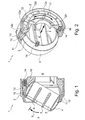
- the Figures 1 and 2 show an air outlet 1, which has a circular housing 2 and a pivotally mounted therein, slidably mounted, spherical-ring-shaped air guide element 3.
- the air guide 3 has an outer contour 4, which has substantially the shape of a ring of a spherical shell. As indicated by an arrow 5, the air guide element 3 can be pivoted in the housing 2.
- two vanes 6, 7 are arranged.
- the air guide element 3 is provided to guide air, which comes from an air duct not shown here, from a back 8 to a front side 9 of the housing 2 and to direct in the desired direction.
- FIG. 1 the housing 2 in its front region on a spherically shaped portion 10 which is lined with felt material 11.
- the felt material 11 abuts the outer contour of the air guide element 3.
- the outer contour 4 thus slides on the felt material 11.
- the clamping element 12 does not press directly against the bearing ring 13. Rather, several compression springs 14 are arranged in the circumferential direction of the air outlet 1, which transmit the force exerted by the clamping element 12 clamping force on the bearing ring 13.
- the inner contour of the bearing ring 13 is designed spherical. Between the inner contour of the bearing ring 13 and the outer contour 4 of the spoiler 3 felt material 15 is also arranged.
- the clamping element 12 has an outer ring 12a and an inner ring 12b, which are connected to each other via radial lamellae 12c, 12d.
- an external thread 12e is provided, which is screwed into an internal thread 16, which is provided in the rear region of the housing inner side.
Landscapes
- Physics & Mathematics (AREA)
- Thermal Sciences (AREA)
- Engineering & Computer Science (AREA)
- Mechanical Engineering (AREA)
- Air-Flow Control Members (AREA)
- Air-Conditioning For Vehicles (AREA)
Abstract
Description
- Die vorliegende Erfindung betrifft eine Luftauslasseinrichtung für Fahrzeugklimaanlagen gemäß dem Oberbegriff des Patentanspruches 1.
- Im Innenraum moderner Fahrzeuge sind eine Vielzahl von Luftauslasseinrichtungen vorgesehen. Auf der der Fahrgastraummitte zugewandten Seite der Instrumententafel sind üblicherweise mehrere Luftauslässe mit schwenkbar angeordneten Luftleitelementen vorgesehen. Die Luftleitelemente können unterschiedlichste Formen haben und unmittelbar von Hand oder über Verstellräder o.ä. in die gewünschte Ausströmrichtung verschwenkt werden. Seit Jahrzehnten bekannt sind auch Luftauslasseinrichtungen mit einem Gehäuse und einem darin von Hand verschwenkbar angeordneten kugelringförmigen Luftleitelement.
- Die kugelringförmigen Luftleitelemente sind im Gehäuse mit einer gewissen Vorspannkraft "vorgespannt". Die Vorspannkraft bestimmt die zum Verschwenken erforderliche Verstellkraft. Eine Verstellung der Vorspannkraft ist üblicherweise nur möglich, wenn die Luftauslasseinrichtung "ausgebaut" ist. Bei manchen Anordnungen beeinflussen auch Dekorelemente, welche die Luftauslasseinrichtung fahrgastraumseitig umgeben, die Vorspann- und somit die für das Verschwenken erforderlichen Verstellkräfte. Üblicherweise ist ein Einstellen des Spiels bzw. der Vorspannkräfte mittels Federn und Einstellschrauben möglich, die nur von der Rückseite der Luftauslasseinrichtung her zugänglich sind. Dies ist zeit- und entsprechend kostenaufwändig.
- Aufgabe der Erfindung ist es, eine Luftauslasseinrichtung mit einem kugelringförmigen Luftleitelement zu schaffen, bei der die zum Verschwenken des Luftleitelements benötigte Verstellkraft auch im eingebauten Zustand der Luftauslasseinrichtung justierbar ist.
- Diese Aufgabe wird durch die Merkmale des Patentanspruches 1 gelöst. Vorteilhafte Ausgestaltungen und Weiterbildungen der Erfindung sind den Unteransprüchen zu entnehmen.
- Ausgangspunkt der Erfindung ist eine Luftauslasseinrichtung für Fahrzeugklimaanlagen, die ein Gehäuse mit einer Vorderseite und einer Rückseite und ein in dem Gehäuse schwenkbar und gleitend gelagertes kugelringförmiges Luftleitelement aufweist. Das Luftleitelement ist dazu vorgesehen, entsprechend seiner Schwenkstellung, Luft von der Rückseite in Richtung zur Vorderseite, d.h. in einen Fahrgastraum eines Fahrzeugs zu leiten, wobei die Luft das kugelringförmige Luftleitelement durchströmt. Ferner ist ein Spannelement vorgesehen, welches eine von der Rückseite in Richtung der Vorderseite wirkende Lager- bzw. Spannkraft auf das kugelringförmige Luftleitelement ausübt. Die Lager- bzw. Spannkraft bestimmt in erheblichem Maße die zum Verschwenken des Luftleitelements erforderliche Verstellkraft.
- Der Kern der Erfindung besteht darin, dass das Spannelement von der Vorderseite des Gehäuses aus durch das kugelringförmige Luftleitelement hindurch relativ zu dem Gehäuse verdrehbar ist, wobei durch Verdrehen des Spannelements die Lager- bzw. Spannkraft verstellbar ist.
- Zum Justieren der Lager- bzw. Spannkraft wird vorzugsweise ein Einstellwerkzeug verwendet. Bei dem Einstellwerkzeug kann es sich z.B. um ein gabelförmiges Werkzeug mit zwei oder mehreren "Zinken" bzw. Gabelarmen handeln, die von der Vorderseite der Luftauslasseinrichtung her durch das kugelringförmige Luftleitelement hindurch geführt werden und dann "von hinten her" an dem Spannelement angreifen bzw. in zugeordnete Ausnehmungen bzw. in ein zugeordnetes Rastprofil, das an der Rückseite des Spannelements vorgesehen sein kann, eingreifen. Mittels eines derartigen Justierwerkzeugs kann das Spannelement relativ zum Gehäuse verdreht und somit die Lager- bzw. Spannkraft eingestellt werden, ohne dass die Luftauslasseinrichtung aus dem Fahrzeug, insbesondere aus der Instrumententafel oder der Mittelkonsole des Fahrzeugs ausgebaut werden muss. Selbstverständlich sind für einen derartigen "Kugelausströmer" auch andere "Einbauorte" denkbar, wie z.B. der Innenbereich der so genannten "B-Säule" o.ä.
- Das Spannelement kann ringförmig gestaltet sein. Beispielsweise kann das Spannelement mit einem Außengewinde versehen sein, das in ein im Bereich der Rückseite des Gehäuses im Gehäuse vorgesehenes Innengewinde eingeschraubt ist. Durch Verdrehen des Spannelements ergibt sich eine der Gewindesteigung entsprechende axiale Verschiebung des Spannelements und somit eine entsprechende Veränderung der Lager- bzw. Vorspannkraft.
- Nach einer Weiterbildung der Erfindung weist das Spannelement einen äußeren Ring und einen inneren Ring auf, wobei der innere Ring über mehrere radial angeordnete Rippen mit dem äußeren Ring verbunden ist. Der innere Ring kann dabei die Funktion eines Schwenkanschlags für das Luftleitelement übernehmen. Bei maximaler Auslenkung des Luftleitelements liegt also ein Randbereich des kugelringförmigen Luftleitelements an dem inneren Ring des Spannelements an und begrenzt somit ein weiteres Verschwenken des Luftleitelements.
- Zum Justieren der Lager- bzw. Spannkraft kann, wie bereits erwähnt, ein gabel- bzw. zinkenartiges Einstellwerkzeug verwendet werden. Es kann vorgesehen sein, dass die Gabelarme bzw. Zinken des Einstellwerkzeugs dabei mit den radialen Rippen zusammenwirken, welche den inneren und den äußeren Ring des Spannelements miteinander verbinden. Durch Aufbringen eines Drehmoments kann die Drehstellung des Spannelements und somit die Lager- bzw. Spannkraft justiert werden.
- Vorzugsweise wirkt das Spannelement nicht unmittelbar mit dem Luftleitelement zusammen. Vielmehr kann zwischen dem Spannelement und dem Luftleitelement ein Lagerring vorgesehen sein, der die von dem Spannelement aufgebrachte Axial- bzw. Lagerkraft auf das kugelringförmige Luftleitelement überträgt. Um eine über den Umfang des kugelringförmigen Luftleitelements gleichmäßig verteilte Lager- bzw. Spannkraft zu erzeugen, können zwischen dem Spannelement und dem Lagerring in Umfangsrichtung des Luftleitelements verteilt mehrere Druckfederelemente, z.B. in Form kleiner Spiralfedern, angeordnet sein.
- Vorzugsweise ist eine Verdrehsicherung vorgesehen, welche eine Relativdrehung des Lagerrings relativ zu dem Gehäuse der Luftauslasseinrichtung verhindert. Die Verdrehsicherung kann beispielsweise durch ein oder mehrere in Umfangsrichtung verteilt angeordnete, in Axialrichtung der Luftauslasseinrichtung verlaufende Längsrippen gebildet sein, die in zugeordnete Nuten eingreifen. Die Längsrippen können beispielsweise an dem Lagerring vorgesehen sein. Die zugeordneten Nuten können im Gehäuse vorgesehen sein oder umgekehrt.
- Zur Verbesserung des Bedienkomforts sowie zur Vermeidung störender Geräusche kann zwischen einem Außenumfang des kugelringförmigen Luftleitelements und dem Lagerring z.B. eine Filzschicht angeordnet sein. Beim Verschwenken des Luftleitelements relativ zu dem Gehäuse gleitet eine Außenseite des Luftleitelements auf dem Filz. Die Filzschicht kann dabei in den Lagerring eingeklebt sein.
- Ferner kann zwischen dem Außenumfang des Luftleitelements und einer Innenseite des vorderen Gehäusebereichs eine Filzschicht angeordnet sein.
- Anstatt Filz kann selbstverständlich auch ein anderes Material verwendet werden.
- Im Folgenden wird die Erfindung im Zusammenhang mit der Zeichnung näher erläutert. Es zeigen:
- Figur 1
- Einen Querschnitt in Axialrichtung durch eine Luftauslasseinrichtung gemäß der Erfindung; und
- Figur 2
- einen Querschnitt senkrecht zur Axialrichtung der in
Figur 1 gezeigten Luftauslasseinrichtung. - Die
Figuren 1 und 2 zeigen eine Luftauslasseinrichtung 1, die ein kreisrundes Gehäuse 2 und ein darin schwenkbar angeordnetes, gleitend gelagertes, kugelringförmiges Luftleitelement 3 aufweist. Das Luftleitelement 3 weist eine Außenkontur 4 auf, die im Wesentlichen die Form eines Rings einer Kugelschale aufweist. Wie durch einen Pfeil 5 angedeutet ist, kann das Luftleitelement 3 in dem Gehäuse 2 verschwenkt werden. In dem Luftleitelement 3 sind zwei Luftleitlamellen 6, 7 angeordnet. Das Luftleitelement 3 ist dazu vorgesehen, Luft, die aus einem hier nicht näher dargestellten Luftleitkanal kommt, von einer Rückseite 8 zu einer Vorderseite 9 des Gehäuses 2 zu leiten und in die gewünschte Richtung zu lenken. - Wie aus
Figur 1 ersichtlich ist, weist das Gehäuse 2 in seinem vorderen Bereich einen kugelförmig gestalteten Abschnitt 10 auf, der mit Filzmaterial 11 ausgekleidet ist. Das Filzmaterial 11 liegt an der Außenkontur des Luftleitelements 3 an. Beim Verschwenken des Luftleitelements 3 gleitet die Außenkontur 4 somit auf dem Filzmaterial 11. Von der Rückseite 8 her wird das Luftleitelement 3 durch ein Spannelement 12 abgestützt, wobei zwischen dem Spannelement 12 und dem Luftleitelement 3 ein Lagerring 13 angeordnet ist. Wie am besten ausFigur 1 ersichtlich ist, drückt das Spannelement 12 nicht unmittelbar gegen den Lagerring 13. Vielmehr sind in Umfangsrichtung der Luftauslasseinrichtung 1 mehrere Druckfedern 14 angeordnet, welche die vom Spannelement 12 ausgeübte Spannkraft auf den Lagerring 13 übertragen. Die Innenkontur des Lagerrings 13 ist kugelförmig gestaltet. Zwischen der Innenkontur des Lagerrings 13 und der Außenkontur 4 des Luftleitelements 3 ist ebenfalls Filzmaterial 15 angeordnet. - Wie aus
Figur 2 ersichtlich ist, weist das Spannelement 12 einen Außenring 12a und einen Innenring 12b auf, die über radiale Lamellen 12c, 12d miteinander verbunden sind. Am Außenumfang des Spannelements 12 ist ein Außengewinde 12e vorgesehen, das in ein Innengewinde 16, das im rückwärtigen Bereich der Gehäuseinnenseite vorgesehen ist, eingeschraubt ist. Durch Drehen des Spannelements 12, was inFigur 2 durch einen Pfeil 17 angedeutet ist, kann das Spannelement 12 entsprechend der Gewindesteigung in Axialrichtung verschoben werden. Dadurch kann die Vorspannung des Luftleitelements 3 und somit die für eine Verschwenkbewegung des Luftleitelements 3 erforderliche Schwenkkraft justiert werden. - Im Vergleich zu herkömmlichen Luftauslasseinrichtungen mit kugelringförmigen Luftleitelementen besteht ein wesentlicher Vorteil der in den
Figuren 1 und 2 gezeigten Luftauslasseinrichtung darin, dass mittels eines geeigneten gabel- oder zinkenförmigen Werkzeugs, das von der Vorderseite 9 durch das Luftleitelement 3 hindurch in die Luftauslasseinrichtung 1 eingeführt wird, das Spannelement 12 entsprechend dem Pfeil 17 verdreht und somit die Vorspannung des Luftleitelements 3 justiert werden kann. Die Justierung im eingebauten Zustand wird somit möglich.
Claims (9)
- Luftauslasseinrichtung (1) für Fahrzeugklimaanlagen, mit- einem Gehäuse (2), das eine Rückseite (8) und eine Vorderseite (9) aufweist,- einem kugelringförmigen Luftleitelement (3), das schwenkbar und gleitend gelagert in dem Gehäuse (2) angeordnet ist und das dazu vorgesehen ist, entsprechend seiner Schwenkstellung, Luft von der Rückseite (8) zu der Vorderseite (9) zu leiten, wobei die Luft das Luftleitelement (3) durchströmt,- einem Spannelement (12), welche eine von der Rückseite (8) in Richtung der Vorderseite (9) wirkende Lagerkraft auf das Luftleitelement (3) ausübt, wobei die zum Verschwenken des Luftleitelements (3) erforderliche Kraft von der Lagerkraft abhängt,dadurch gekennzeichnet, dass das Spannelement (12) von der Vorderseite (9) des Gehäuses (2) durch das Luftleitelement (3) hindurch relativ zu dem Gehäuse (2) verdrehbar ist, wobei durch Verdrehen des Spannelements (12) die Lagerkraft verstellbar ist.
- Luftauslasseinrichtung (1) nach Anspruch 1,
dadurch gekennzeichnet, dass das Spannelement (12) eine ringförmige Gestalt aufweist. - Luftauslasseinrichtung (1) nach einem der Ansprüche 1 oder 2,
dadurch gekennzeichnet, dass das Spannelement (12) ein Außengewinde (12e) aufweist, das in ein im Bereich der Rückseite (8) im Gehäuse (2) vorgesehenes Innengewinde (16) eingeschraubt ist. - Luftauslasseinrichtung (1) nach einem der Ansprüche 1 bis 3,
dadurch gekennzeichnet, dass das Spannelement (12) einen äußeren Ring (12a) und einen inneren Ring (12b) aufweist, wobei der innere Ring (12b) über mehrere radial angeordnete Rippen (12c, 12d) mit dem äußeren Ring (12a) verbunden ist. - Luftauslasseinrichtung (1) nach Anspruch 4,
dadurch gekennzeichnet, dass der innere Ring (12b) einen Schwenkanschlag für das Luftleitelement (3) bildet. - Luftauslasseinrichtung (1) nach einem der Ansprüche 1 bis 5,
dadurch gekennzeichnet, dass zwischen dem Spannelement (12) und dem Luftleitelement (3) ein Lagerring (13) angeordnet ist, der die von dem Spannelement (12) aufgebrachte Lagerkraft auf das Luftleitelement (3) überträgt. - Luftauslasseinrichtung (1) nach Anspruch 6,
dadurch gekennzeichnet, dass zwischen dem Spannelement (12) und dem Lagerring (13) in Umfangsrichtung des Luftleitelements (3) verteilt mehrere Federelemente (14) angeordnet sind. - Luftauslasseinrichtung (1) nach einem der Ansprüche 1 bis 7,
dadurch gekennzeichnet, dass zwischen einem Außenumfang (4) und des Luftleitelements (3) und einer Innenseite eines vorderen Gehäuseteils Filzmaterial angeordnet ist. - Luftauslasseinrichtung (1) nach einem der Ansprüche 6 bis 8,
dadurch gekennzeichnet, dass zwischen dem Außenumfang (4) des Luftleitelements (3) und dem Lagerring (13) Filzmaterial angeordnet ist, wobei bei einem Verschwenken des Luftleitelements (3) relativ zu dem Gehäuse (2) eine Außenseite (4) des Luftleitelements (3) auf dem Filz gleitet.
Applications Claiming Priority (1)
| Application Number | Priority Date | Filing Date | Title |
|---|---|---|---|
| DE102008054360A DE102008054360A1 (de) | 2008-11-03 | 2008-11-03 | Luftauslasseinrichtung für Fahrzeugklimaanlagen |
Publications (2)
| Publication Number | Publication Date |
|---|---|
| EP2181874A1 true EP2181874A1 (de) | 2010-05-05 |
| EP2181874B1 EP2181874B1 (de) | 2010-12-01 |
Family
ID=41395050
Family Applications (1)
| Application Number | Title | Priority Date | Filing Date |
|---|---|---|---|
| EP09012551A Active EP2181874B1 (de) | 2008-11-03 | 2009-10-05 | Luftauslasseeinrichtung für Fahrzeugklimaanlagen |
Country Status (3)
| Country | Link |
|---|---|
| EP (1) | EP2181874B1 (de) |
| AT (1) | ATE490105T1 (de) |
| DE (2) | DE102008054360A1 (de) |
Cited By (6)
| Publication number | Priority date | Publication date | Assignee | Title |
|---|---|---|---|---|
| EP2374642A1 (de) * | 2010-04-12 | 2011-10-12 | TRW Automotive Electronics & Components GmbH | Luftausströmer |
| WO2012013313A1 (de) * | 2010-07-26 | 2012-02-02 | Trw Automotive Electronics & Components Gmbh | Luftausströmer |
| WO2015140809A1 (en) * | 2014-03-21 | 2015-09-24 | Faurecia Interior Systems India Pvt. Ltd. | Air vent device comprising a deflector element movable on a guiding rail |
| FR3026353A1 (fr) * | 2014-09-30 | 2016-04-01 | Faurecia Interieur Ind | Aerateur et vehicule comprenant un tel aerateur |
| CN107036161A (zh) * | 2016-02-04 | 2017-08-11 | 青岛海高设计制造有限公司 | 空调转向机构及空调 |
| US20190092142A1 (en) * | 2017-09-26 | 2019-03-28 | Ford Global Technologies, Llc | Air outlet for controlling an air flow |
Citations (4)
| Publication number | Priority date | Publication date | Assignee | Title |
|---|---|---|---|---|
| DE1892765U (de) * | 1964-01-23 | 1964-05-14 | Happich Gmbh Gebr | Luftduese. |
| DE1954305U (de) * | 1966-11-19 | 1967-01-26 | Happich Gmbh Gebr | Lueftungsvorrichtung. |
| DE2538235A1 (de) * | 1975-08-28 | 1977-03-10 | Happich Gmbh Gebr | Kugelluefter, insbesondere fuer fahrzeuge |
| WO1993002881A1 (en) * | 1991-08-02 | 1993-02-18 | Pieter Johannes Van Ouwerkerk | Outflow nozzle |
Family Cites Families (4)
| Publication number | Priority date | Publication date | Assignee | Title |
|---|---|---|---|---|
| DE1929898U (de) * | 1965-09-15 | 1965-12-23 | Carl Wilhelm Cleff K G | Luftfuehrungsduese. |
| DE2452594C3 (de) * | 1974-11-06 | 1978-05-18 | Daimler-Benz Ag, 7000 Stuttgart | Unsichtbare Befestigung eines runden Teiles an einer Bedienungsfrontplatte eines Fahrzeuges |
| JPS5914669Y2 (ja) * | 1979-11-21 | 1984-04-28 | 日産自動車株式会社 | ベンチレ−シヨングリル |
| DE102004019755A1 (de) * | 2004-04-23 | 2005-11-17 | Fischer Automotive Systems Gmbh | Lüftungsdüse |
-
2008
- 2008-11-03 DE DE102008054360A patent/DE102008054360A1/de not_active Ceased
-
2009
- 2009-10-05 AT AT09012551T patent/ATE490105T1/de active
- 2009-10-05 EP EP09012551A patent/EP2181874B1/de active Active
- 2009-10-05 DE DE502009000218T patent/DE502009000218D1/de active Active
Patent Citations (4)
| Publication number | Priority date | Publication date | Assignee | Title |
|---|---|---|---|---|
| DE1892765U (de) * | 1964-01-23 | 1964-05-14 | Happich Gmbh Gebr | Luftduese. |
| DE1954305U (de) * | 1966-11-19 | 1967-01-26 | Happich Gmbh Gebr | Lueftungsvorrichtung. |
| DE2538235A1 (de) * | 1975-08-28 | 1977-03-10 | Happich Gmbh Gebr | Kugelluefter, insbesondere fuer fahrzeuge |
| WO1993002881A1 (en) * | 1991-08-02 | 1993-02-18 | Pieter Johannes Van Ouwerkerk | Outflow nozzle |
Cited By (16)
| Publication number | Priority date | Publication date | Assignee | Title |
|---|---|---|---|---|
| CN102213480A (zh) * | 2010-04-12 | 2011-10-12 | Trw车辆电气与零件有限公司 | 空气排出器 |
| CN102213480B (zh) * | 2010-04-12 | 2013-10-30 | Trw车辆电气与零件有限公司 | 空气排出器 |
| US8740677B2 (en) | 2010-04-12 | 2014-06-03 | Trw Automotive Electronics & Components Gmbh | Air vent |
| EP2374642A1 (de) * | 2010-04-12 | 2011-10-12 | TRW Automotive Electronics & Components GmbH | Luftausströmer |
| US9434238B2 (en) | 2010-07-26 | 2016-09-06 | Itw Fastener Products Gmbh | Air diffuser |
| WO2012013313A1 (de) * | 2010-07-26 | 2012-02-02 | Trw Automotive Electronics & Components Gmbh | Luftausströmer |
| CN103201126A (zh) * | 2010-07-26 | 2013-07-10 | Trw车辆电气与零件有限公司 | 排风装置 |
| CN103201126B (zh) * | 2010-07-26 | 2015-06-17 | Trw车辆电气与零件有限公司 | 排风装置 |
| GB2540887B (en) * | 2014-03-21 | 2019-03-27 | Faurecia Interior Systems India Private Ltd | Air vent device comprising a deflector element movable on a guiding rail |
| GB2540887A (en) * | 2014-03-21 | 2017-02-01 | Faurecia Interior Systems India Private Ltd | Air vent device comprising a deflector element movable on a guiding rail |
| WO2015140809A1 (en) * | 2014-03-21 | 2015-09-24 | Faurecia Interior Systems India Pvt. Ltd. | Air vent device comprising a deflector element movable on a guiding rail |
| FR3026353A1 (fr) * | 2014-09-30 | 2016-04-01 | Faurecia Interieur Ind | Aerateur et vehicule comprenant un tel aerateur |
| US10549606B2 (en) | 2014-09-30 | 2020-02-04 | Faurecia Interieur Industrie | Aerator and vehicle comprising such an aerator |
| CN107036161A (zh) * | 2016-02-04 | 2017-08-11 | 青岛海高设计制造有限公司 | 空调转向机构及空调 |
| US20190092142A1 (en) * | 2017-09-26 | 2019-03-28 | Ford Global Technologies, Llc | Air outlet for controlling an air flow |
| US11390144B2 (en) * | 2017-09-26 | 2022-07-19 | Ford Global Technologies, Llc | Air outlet for controlling an air flow |
Also Published As
| Publication number | Publication date |
|---|---|
| DE502009000218D1 (de) | 2011-01-13 |
| EP2181874B1 (de) | 2010-12-01 |
| DE102008054360A1 (de) | 2010-05-06 |
| ATE490105T1 (de) | 2010-12-15 |
Similar Documents
| Publication | Publication Date | Title |
|---|---|---|
| EP2181874B1 (de) | Luftauslasseeinrichtung für Fahrzeugklimaanlagen | |
| EP2139710B1 (de) | Luftausströmer | |
| DE202008008891U1 (de) | Luftdüse | |
| EP2281124A2 (de) | Kugelgelenk | |
| DE102015010348A1 (de) | Vorrichtung zur Befestigung eines Verschleißsensors an einem Bremshebel einer Fahrzeugbremse | |
| DE102016216496A1 (de) | Gewindetrieb | |
| DE102018200187A1 (de) | Armlehnenanordnung für einen Kraftfahrzeugsitz | |
| EP2334502A1 (de) | Verriegelungsmechanismus sowie fahrzeugseitige kupplungsbaugruppe einer anhängerkupplung | |
| DE102007039858B4 (de) | Kugelgelenk | |
| DE102011081935A1 (de) | Kugelgelenk | |
| EP2040948A1 (de) | Anbindungsvorrichtung für eine halteeinrichtung eines deckels eines öffnungsfähigen fahrzeugdaches | |
| DE102019216772B4 (de) | Luftausströmeranordnung | |
| EP1933053A1 (de) | Reibbelag und Reibungskupplung mit einem solchen Reibbelag | |
| EP2385268B1 (de) | Im Bremssattel einer Scheibenbremse angeordnete Zuspanneinrichtung | |
| DE112011100784T5 (de) | Wischervorrichtung | |
| EP1747109B1 (de) | Luftausströmer, insbesondere für ein kraftfahrzeug | |
| DE102010020026A1 (de) | Anschlagvorrichtung und Ladeeinrichtung | |
| DE102019209453B4 (de) | Sperrklinke für eine Parksperrenanordnung | |
| DE102018205324B4 (de) | Kupplungspedalanordnung und Kupplungsbetätigungssystem | |
| DE102013001129A1 (de) | Luftauslass und Fahrzeug mit einem derartigen Luftauslass | |
| DE102016218271A1 (de) | Manteleinheit für eine verstellbare Lenksäule eines Kraftfahrzeugs | |
| DE202015008911U1 (de) | Zuspannvorrichtung für eine Scheibenbremse | |
| EP1733289B1 (de) | Drehschalter | |
| DE102017007960A1 (de) | Feststellvorrichtung für eine verstellbare Lenksäule eines Fahrzeugs | |
| DE102017223298A1 (de) | Lenksäule für ein Kraftfahrzeug |
Legal Events
| Date | Code | Title | Description |
|---|---|---|---|
| PUAI | Public reference made under article 153(3) epc to a published international application that has entered the european phase |
Free format text: ORIGINAL CODE: 0009012 |
|
| AK | Designated contracting states |
Kind code of ref document: A1 Designated state(s): AT BE BG CH CY CZ DE DK EE ES FI FR GB GR HR HU IE IS IT LI LT LU LV MC MK MT NL NO PL PT RO SE SI SK SM TR |
|
| AX | Request for extension of the european patent |
Extension state: AL BA RS |
|
| GRAP | Despatch of communication of intention to grant a patent |
Free format text: ORIGINAL CODE: EPIDOSNIGR1 |
|
| 17P | Request for examination filed |
Effective date: 20100522 |
|
| GRAS | Grant fee paid |
Free format text: ORIGINAL CODE: EPIDOSNIGR3 |
|
| GRAA | (expected) grant |
Free format text: ORIGINAL CODE: 0009210 |
|
| AK | Designated contracting states |
Kind code of ref document: B1 Designated state(s): AT BE BG CH CY CZ DE DK EE ES FI FR GB GR HR HU IE IS IT LI LT LU LV MC MK MT NL NO PL PT RO SE SI SK SM TR |
|
| REG | Reference to a national code |
Ref country code: GB Ref legal event code: FG4D Free format text: NOT ENGLISH |
|
| REG | Reference to a national code |
Ref country code: CH Ref legal event code: EP |
|
| REG | Reference to a national code |
Ref country code: IE Ref legal event code: FG4D |
|
| REF | Corresponds to: |
Ref document number: 502009000218 Country of ref document: DE Date of ref document: 20110113 Kind code of ref document: P |
|
| REG | Reference to a national code |
Ref country code: NL Ref legal event code: VDEP Effective date: 20101201 |
|
| PG25 | Lapsed in a contracting state [announced via postgrant information from national office to epo] |
Ref country code: LT Free format text: LAPSE BECAUSE OF FAILURE TO SUBMIT A TRANSLATION OF THE DESCRIPTION OR TO PAY THE FEE WITHIN THE PRESCRIBED TIME-LIMIT Effective date: 20101201 Ref country code: NO Free format text: LAPSE BECAUSE OF FAILURE TO SUBMIT A TRANSLATION OF THE DESCRIPTION OR TO PAY THE FEE WITHIN THE PRESCRIBED TIME-LIMIT Effective date: 20110301 |
|
| LTIE | Lt: invalidation of european patent or patent extension |
Effective date: 20101201 |
|
| PG25 | Lapsed in a contracting state [announced via postgrant information from national office to epo] |
Ref country code: FI Free format text: LAPSE BECAUSE OF FAILURE TO SUBMIT A TRANSLATION OF THE DESCRIPTION OR TO PAY THE FEE WITHIN THE PRESCRIBED TIME-LIMIT Effective date: 20101201 Ref country code: SI Free format text: LAPSE BECAUSE OF FAILURE TO SUBMIT A TRANSLATION OF THE DESCRIPTION OR TO PAY THE FEE WITHIN THE PRESCRIBED TIME-LIMIT Effective date: 20101201 Ref country code: BG Free format text: LAPSE BECAUSE OF FAILURE TO SUBMIT A TRANSLATION OF THE DESCRIPTION OR TO PAY THE FEE WITHIN THE PRESCRIBED TIME-LIMIT Effective date: 20110301 Ref country code: NL Free format text: LAPSE BECAUSE OF FAILURE TO SUBMIT A TRANSLATION OF THE DESCRIPTION OR TO PAY THE FEE WITHIN THE PRESCRIBED TIME-LIMIT Effective date: 20101201 Ref country code: CY Free format text: LAPSE BECAUSE OF FAILURE TO SUBMIT A TRANSLATION OF THE DESCRIPTION OR TO PAY THE FEE WITHIN THE PRESCRIBED TIME-LIMIT Effective date: 20101201 Ref country code: LV Free format text: LAPSE BECAUSE OF FAILURE TO SUBMIT A TRANSLATION OF THE DESCRIPTION OR TO PAY THE FEE WITHIN THE PRESCRIBED TIME-LIMIT Effective date: 20101201 Ref country code: HR Free format text: LAPSE BECAUSE OF FAILURE TO SUBMIT A TRANSLATION OF THE DESCRIPTION OR TO PAY THE FEE WITHIN THE PRESCRIBED TIME-LIMIT Effective date: 20101201 Ref country code: SE Free format text: LAPSE BECAUSE OF FAILURE TO SUBMIT A TRANSLATION OF THE DESCRIPTION OR TO PAY THE FEE WITHIN THE PRESCRIBED TIME-LIMIT Effective date: 20101201 |
|
| REG | Reference to a national code |
Ref country code: IE Ref legal event code: FD4D |
|
| PG25 | Lapsed in a contracting state [announced via postgrant information from national office to epo] |
Ref country code: GR Free format text: LAPSE BECAUSE OF FAILURE TO SUBMIT A TRANSLATION OF THE DESCRIPTION OR TO PAY THE FEE WITHIN THE PRESCRIBED TIME-LIMIT Effective date: 20110302 |
|
| PG25 | Lapsed in a contracting state [announced via postgrant information from national office to epo] |
Ref country code: CZ Free format text: LAPSE BECAUSE OF FAILURE TO SUBMIT A TRANSLATION OF THE DESCRIPTION OR TO PAY THE FEE WITHIN THE PRESCRIBED TIME-LIMIT Effective date: 20101201 Ref country code: EE Free format text: LAPSE BECAUSE OF FAILURE TO SUBMIT A TRANSLATION OF THE DESCRIPTION OR TO PAY THE FEE WITHIN THE PRESCRIBED TIME-LIMIT Effective date: 20101201 Ref country code: ES Free format text: LAPSE BECAUSE OF FAILURE TO SUBMIT A TRANSLATION OF THE DESCRIPTION OR TO PAY THE FEE WITHIN THE PRESCRIBED TIME-LIMIT Effective date: 20110312 Ref country code: IS Free format text: LAPSE BECAUSE OF FAILURE TO SUBMIT A TRANSLATION OF THE DESCRIPTION OR TO PAY THE FEE WITHIN THE PRESCRIBED TIME-LIMIT Effective date: 20110401 Ref country code: PT Free format text: LAPSE BECAUSE OF FAILURE TO SUBMIT A TRANSLATION OF THE DESCRIPTION OR TO PAY THE FEE WITHIN THE PRESCRIBED TIME-LIMIT Effective date: 20110401 Ref country code: IE Free format text: LAPSE BECAUSE OF FAILURE TO SUBMIT A TRANSLATION OF THE DESCRIPTION OR TO PAY THE FEE WITHIN THE PRESCRIBED TIME-LIMIT Effective date: 20101201 |
|
| PG25 | Lapsed in a contracting state [announced via postgrant information from national office to epo] |
Ref country code: SK Free format text: LAPSE BECAUSE OF FAILURE TO SUBMIT A TRANSLATION OF THE DESCRIPTION OR TO PAY THE FEE WITHIN THE PRESCRIBED TIME-LIMIT Effective date: 20101201 Ref country code: RO Free format text: LAPSE BECAUSE OF FAILURE TO SUBMIT A TRANSLATION OF THE DESCRIPTION OR TO PAY THE FEE WITHIN THE PRESCRIBED TIME-LIMIT Effective date: 20101201 Ref country code: PL Free format text: LAPSE BECAUSE OF FAILURE TO SUBMIT A TRANSLATION OF THE DESCRIPTION OR TO PAY THE FEE WITHIN THE PRESCRIBED TIME-LIMIT Effective date: 20101201 |
|
| PLBE | No opposition filed within time limit |
Free format text: ORIGINAL CODE: 0009261 |
|
| STAA | Information on the status of an ep patent application or granted ep patent |
Free format text: STATUS: NO OPPOSITION FILED WITHIN TIME LIMIT |
|
| PG25 | Lapsed in a contracting state [announced via postgrant information from national office to epo] |
Ref country code: DK Free format text: LAPSE BECAUSE OF FAILURE TO SUBMIT A TRANSLATION OF THE DESCRIPTION OR TO PAY THE FEE WITHIN THE PRESCRIBED TIME-LIMIT Effective date: 20101201 |
|
| 26N | No opposition filed |
Effective date: 20110902 |
|
| REG | Reference to a national code |
Ref country code: DE Ref legal event code: R097 Ref document number: 502009000218 Country of ref document: DE Effective date: 20110902 |
|
| BERE | Be: lapsed |
Owner name: BAYERISCHE MOTOREN WERKE A.G. Effective date: 20111031 |
|
| PG25 | Lapsed in a contracting state [announced via postgrant information from national office to epo] |
Ref country code: MC Free format text: LAPSE BECAUSE OF NON-PAYMENT OF DUE FEES Effective date: 20111031 |
|
| PG25 | Lapsed in a contracting state [announced via postgrant information from national office to epo] |
Ref country code: BE Free format text: LAPSE BECAUSE OF NON-PAYMENT OF DUE FEES Effective date: 20111031 |
|
| PG25 | Lapsed in a contracting state [announced via postgrant information from national office to epo] |
Ref country code: MK Free format text: LAPSE BECAUSE OF FAILURE TO SUBMIT A TRANSLATION OF THE DESCRIPTION OR TO PAY THE FEE WITHIN THE PRESCRIBED TIME-LIMIT Effective date: 20101201 Ref country code: MT Free format text: LAPSE BECAUSE OF FAILURE TO SUBMIT A TRANSLATION OF THE DESCRIPTION OR TO PAY THE FEE WITHIN THE PRESCRIBED TIME-LIMIT Effective date: 20101201 |
|
| PG25 | Lapsed in a contracting state [announced via postgrant information from national office to epo] |
Ref country code: SM Free format text: LAPSE BECAUSE OF FAILURE TO SUBMIT A TRANSLATION OF THE DESCRIPTION OR TO PAY THE FEE WITHIN THE PRESCRIBED TIME-LIMIT Effective date: 20101201 |
|
| PG25 | Lapsed in a contracting state [announced via postgrant information from national office to epo] |
Ref country code: LU Free format text: LAPSE BECAUSE OF NON-PAYMENT OF DUE FEES Effective date: 20111005 |
|
| PG25 | Lapsed in a contracting state [announced via postgrant information from national office to epo] |
Ref country code: TR Free format text: LAPSE BECAUSE OF FAILURE TO SUBMIT A TRANSLATION OF THE DESCRIPTION OR TO PAY THE FEE WITHIN THE PRESCRIBED TIME-LIMIT Effective date: 20101201 |
|
| PG25 | Lapsed in a contracting state [announced via postgrant information from national office to epo] |
Ref country code: HU Free format text: LAPSE BECAUSE OF FAILURE TO SUBMIT A TRANSLATION OF THE DESCRIPTION OR TO PAY THE FEE WITHIN THE PRESCRIBED TIME-LIMIT Effective date: 20101201 |
|
| REG | Reference to a national code |
Ref country code: CH Ref legal event code: PL |
|
| PG25 | Lapsed in a contracting state [announced via postgrant information from national office to epo] |
Ref country code: LI Free format text: LAPSE BECAUSE OF NON-PAYMENT OF DUE FEES Effective date: 20131031 Ref country code: CH Free format text: LAPSE BECAUSE OF NON-PAYMENT OF DUE FEES Effective date: 20131031 |
|
| REG | Reference to a national code |
Ref country code: FR Ref legal event code: PLFP Year of fee payment: 7 |
|
| REG | Reference to a national code |
Ref country code: AT Ref legal event code: MM01 Ref document number: 490105 Country of ref document: AT Kind code of ref document: T Effective date: 20141005 |
|
| PG25 | Lapsed in a contracting state [announced via postgrant information from national office to epo] |
Ref country code: AT Free format text: LAPSE BECAUSE OF NON-PAYMENT OF DUE FEES Effective date: 20141005 |
|
| REG | Reference to a national code |
Ref country code: FR Ref legal event code: PLFP Year of fee payment: 8 |
|
| REG | Reference to a national code |
Ref country code: FR Ref legal event code: PLFP Year of fee payment: 9 |
|
| REG | Reference to a national code |
Ref country code: FR Ref legal event code: PLFP Year of fee payment: 10 |
|
| P01 | Opt-out of the competence of the unified patent court (upc) registered |
Effective date: 20230503 |
|
| PGFP | Annual fee paid to national office [announced via postgrant information from national office to epo] |
Ref country code: DE Payment date: 20251021 Year of fee payment: 17 |
|
| PGFP | Annual fee paid to national office [announced via postgrant information from national office to epo] |
Ref country code: GB Payment date: 20251024 Year of fee payment: 17 |
|
| PGFP | Annual fee paid to national office [announced via postgrant information from national office to epo] |
Ref country code: IT Payment date: 20251031 Year of fee payment: 17 |
|
| PGFP | Annual fee paid to national office [announced via postgrant information from national office to epo] |
Ref country code: FR Payment date: 20251027 Year of fee payment: 17 |