EP2190588B1 - Powder feeding method, powder feeding apparatus and electrostatical powder spray coating apparatus - Google Patents
Powder feeding method, powder feeding apparatus and electrostatical powder spray coating apparatus Download PDFInfo
- Publication number
- EP2190588B1 EP2190588B1 EP08807017A EP08807017A EP2190588B1 EP 2190588 B1 EP2190588 B1 EP 2190588B1 EP 08807017 A EP08807017 A EP 08807017A EP 08807017 A EP08807017 A EP 08807017A EP 2190588 B1 EP2190588 B1 EP 2190588B1
- Authority
- EP
- European Patent Office
- Prior art keywords
- powder
- feed
- valve
- intake valve
- feed chamber
- Prior art date
- Legal status (The legal status is an assumption and is not a legal conclusion. Google has not performed a legal analysis and makes no representation as to the accuracy of the status listed.)
- Active
Links
Images

Classifications
-
- B—PERFORMING OPERATIONS; TRANSPORTING
- B05—SPRAYING OR ATOMISING IN GENERAL; APPLYING FLUENT MATERIALS TO SURFACES, IN GENERAL
- B05B—SPRAYING APPARATUS; ATOMISING APPARATUS; NOZZLES
- B05B7/00—Spraying apparatus for discharge of liquids or other fluent materials from two or more sources, e.g. of liquid and air, of powder and gas
- B05B7/14—Spraying apparatus for discharge of liquids or other fluent materials from two or more sources, e.g. of liquid and air, of powder and gas designed for spraying particulate materials
- B05B7/1404—Arrangements for supplying particulate material
- B05B7/1459—Arrangements for supplying particulate material comprising a chamber, inlet and outlet valves upstream and downstream the chamber and means for alternately sucking particulate material into and removing particulate material from the chamber through the valves
Definitions
- the present invention relates to a powder feeding method, to a powder feeding device and to an electrostatical powder spraycoating apparatus comprising a powder feeding device.
- Dense phase powder pumps comprise at least one feed chamber fitted with a powder intake valve and a powder outlet valve.
- the chamber may be connected alternatively to a vacuum source to aspirate powder, through its open powder intake valve while the powder outlet valve is closed, into the feed chamber, or subsequently thereto to a source of compressed gas, usually compressed air, in order to expel the coating powder from the feed chamber through the open powder outlet valve while the powder intake valve is closed.
- a source of compressed gas usually compressed air
- injectors aspirate coating powder into a flow of feeding air where said powder mixed with this flow and is fed through a discharge conduit to a powder spraycoating tool Such powder spraycoating equipment is known for instance from the European patent document EP 0606577 B1 .
- the dense phase powder pumps are fitted with at least one, usually two feed chambers.
- a vacuum intake of the feed chamber -- in some designs also a compressed air intake in the feed chamber - is fitted with a filter permeable to air but not to coating powder.
- the filter material has conventionally been a sintered material.
- the powder intake and outlet valves are pinch valves that have already been successfully used with injector pumps in feeding thin phase powders because being less susceptible to aggregating powder within them and being more easily cleansed by the gas flow through them than are other types of valves.
- a coating powder feed method and a corresponding device according to the preamble of claims 1 and 7 is known from US 2005/0207901 A1 .
- the object of the present invention is to increase the pumping rate without incurring thereby complex or costly steps.
- the invention allows raising the pumping rate in simple manner.
- the present invention allows more accurately metering the powder feed volume rates.
- a control signal is generated to produce the partial vacuum in the feed chamber a predetermined delay after a control signal opening the powder intake valve was generated, as a result of which the partial vacuum begins increasing in the feed chamber after the above cited delay time beyond opening the powder intake valve.
- the predetermined delay time preferably shall be in the range of 0 to 50 ms for a feed-cycle period of about 200 ms of the feed chamber.
- this embodiment mode does not preclude applying the present invention to other delay times and cycle-periods.
- the present invention attains that the partial vacuum in the feed chamber shall oppose an opening displacement of the powder intake valve -- especially it is a pinch valve -- at least at the time the powder intake valve starts opening, than is the case in the state of the art.
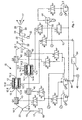
- Fig. 1 schematically shows a coating powder feeding device of the invention containing a dense phase powder pump 10 illustratively fitted with two feed chambers 12 and 14 configured in parallel each in a pump cylinder A respectively B each fitted with a powder intake valve Q1 and Q2 at a powder intake 12.1 and 14.1 and with a powder outlet valve Q3 and Q4 respectively at a powder outlet 12.2 and 12. 4.
- the powder intake valves Q1 and Q2 are shown away from the powder intakes 12.1 respectively 14.1, though in fact they are configured preferably immediately at the powder intakes 12.1 and 14.1.
- the powder outlet valves Q3 and Q4 respectively are shown away from the powder outlets 12.2 and 14.2 for clarity, though practically they are preferably mounted immediately at the powder outlets 12.2 and 14.2.
- each feed chamber 12 and 14 is constituted -- at least over part of its straight length between its powder intake valve Q1 respectively Q2 and its powder outlet valve Q3 and Q4 - by a filter 12.4 and 14.4 enclosing the feed chamber 12 and 14 and separating it from an intermediate chamber 12.5 and 14.5.
- the intermediate chamber 12.5 and 14.5 encloses the filter 12.4 and 14. 4 and is situated in a pump housing 12.6 and 14.6.
- a gas hookup port 12.3 respectively 14.3 is constituted in the pump housing 12.6 and 14. 6 and issues into the intermediate chamber 12.5 and 14.5 and is connected to a connector of a control valve 1.5 and 1.6.
- This hookup port of the control valve 1.5 respectively 1.6 can be loaded alternatively with a partial vacuum or with compressed air by switching this control valve 1.5 or 1.6.
- the filter 12.4 and 14.4 is permeable to gas but impermeable to coating powder. Preferably it is porous and made of a sintered material.
- a powder moving conduit 16 is fitted with a preferably Y-shaped branch 20 with feed conduit branches 16.1 respectively 16.2 to move coating powder 17 out of a powder bin 18 and is connected to allow flow with the powder intake sides of the two powder intake valves Q1 and Q2.
- the powder outlet sides of the two powder outlet valves Q3 and Q4 each are connected by a discharge branch 22.1 respectively 22.2, preferably by a Y-shaped branch 24, to a powder discharge conduit 22.
- the powder discharge conduit 22 may lead to a powder receiving bin or to a powder coating tool 26.
- the manual or automatic spray tool 26 is fitted preferably to at least one high voltage (hv) electrode 28 to electrostatically charge the coating powder 17.
- the hv may be generated by a hv generator 30 integrated into the powder spray tool 26 and supplied from a current or voltage source 32 with electric power.
- the powder intake valves Q1 and Q2 and the powder outlet valves Q3 and Q4 preferably are pinch valves. Their designs may be identical. Using the powder intake valve Q1 as a model, Figs. 2 and 3 schematically show a preferred embodiment mode used also for all other valves Q2, Q3 and Q4. Their valve duct 34 is subtended by the inner surface of a flexible hose 36 separating the valve duct 34 from a pressure chamber 38 on the hose outer side in a housing 39. The valve duct 34 is the hose transmission aperture and is kept open by the tension in the hose 36 as shown in Fig. 2 .
- a compressed gas preferably air
- the hose When introducing a compressed gas, preferably air, into the pressure chamber 38 through a gas hookup 40, the hose is radially compressed and in this manner the valve duct 34 can be kept closed as shown in Fig. 3 .
- the compressed air is then removed from the pressure chamber 38, the hose 36 resumes its initial shape shown in Fig. 2 , wherein said valve duct 34 is open again.
- Fig. 1 shows nine control valves 1.1, 1.2, 1.3, 1.4, 1.5. 1.6, 1.7, 1.8 and 1.9 which may be driven independently from each other by an electronic control 42.
- Fig. 1 also shows three pressure regulators 2.1, 2.2 and 2.3 and a vacuum source 44.
- the vacuum source 44 preferably is a vacuum injector.
- the control valve 1.1 is connected to the powder intake valve Q1 and may alternatively may connect latter's pressure chamber 38 to a source of compressed air 46 or vent it.
- the control valve 1.2 is connected to the other powder intake valve Q2 and is able to alternatively connect its pressure chamber 38 to the compressed air feed conduit 46 or to vent it.
- the control valve 1.3 is connected the powder outlet valve Q3 and is able to alternatively connect its pressure chamber 38 to the compressed air feed conduit 46 or to vent it.
- the control valve 1.4 is connected to the other powder outlet valve Q4 and is able to alternatively connect its pressure chamber 38 to the compressed air feed conduit 46 or to vent it.
- the compressed air feed conduit 46 and the control 42 may be connected to a source of compressed air 48 either directly or by means of pressure regulators.
- one of the pressure regulators namely 2.2, is configured between the control valves 1.1, 1.2, 1.3 and 1.4 on one hand and on the other hand the compressed air feed conduit 46, the closing pressure of the pinch valves Q1, Q2, Q3 and Q4 for powder feed operation being adjustable at said pressure regulator 2.2.
- an additional pressure regulator 2.1 may be used in addition to the pressure regulator 2.2, only one of the two pressure regulators 2.2 or 2.1 being connectable alternatively by means of the control valve 1.9 to the pressure intake side of the control valves 1.1, 1.2, 1.3 and 1.4. Consequently a different air pressure may be set at the second pressure regulator 2.1 than at the pressure regulator 2.2, for instance a higher pressure.
- the higher pressure of the second pressure regulator 2.1 may serve to generate a higher closing pressure in the valves Q1, Q2, Q3 and Q4 designed as pinch valves whenever the feed chambers 12 and 14 are used not for power feeding, but for cleansing with cleansing air.
- Each pump cylinder A and B is fitted with a gas hookup port 12.3 respectively 14.3 to which is connected one of the two control valves 1.5 and 1.6 in order to supply the two feed chambers 12 and 14 alternatingly with compressed conveying air from the control 42 or to connect them to the vacuum source 44 and thereby to evacuate them.
- Compressed air from the compressed air supply conduit 46 can be fed by means of the pressure regulator 2.3 and the control valve 1.7 to a vacuum injector 44 to generate in latter a partial vacuum which can be applied by means of the two independently driven control valves 1.5 and 1.6 alternatively to either of the feed chambers 12 and 14 respectively.
- the control valve 1.7 allows alternatively connecting the vacuum injector 44 in the manner discussed above to the compressed air supply conduit 46 or to vent it.
- the feed chambers 12 and 14 can be connected by means of the control valves 1.5 and 1.6 alternatively to a partial vacuum hookup 50 of the vacuum injector 44 or by means of a compressed air conduit 52 to a compressed air outlet 54 of the control 42.
- the preferred embodiment mode of Fig. 1 further comprises the control valve 1.8 by means of which the pressure side of the two control valves 1.5 and 1.6 of the feed chambers 12 and 14 alternatively can be connected to the compressed air supply conduit 46 of which the pressure exceeds that of the compressed feed air applied by the control 42 through the compressed air feed conduit 52.
- the higher pressure of the compressed air supply conduit 46 may be applied through the control valve 1.8 to the feed chambers 12 and 14 for instance when the feed chambers 12 and 14 and the powder conduits connected to them must be rinsed with compressed air.
- control 42 generates a control signal to the control valve 1.5 or 1.6 to generate the partial vacuum in the feed chamber 12 or the other feed chamber 14, no earlier than simultaneously with a control signal to the control valve 1.1 or 1.2 opening the related powder intake valve Q1 or Q2 in such a way that the partial vacuum in the feed chamber 12 or 14 shall build up, no earlier than simultaneously with opening the powder intake valve Q1 respectively Q2 associated with this feed chamber 12 or 14.
- the control 42 generates the control signal for the control valve 1.5 or 1.6 to generate a partial vacuum in the pertinent feed chamber 12 or 14 at a predetermined time delay after the control signal has been applied to the related control valve 1.1 or 1.2 to open the powder intake valve Q1 or Q2 of the related feed chamber 12 or 14, as a result of which the partial vacuum in the pertinent feed chamber 12 or 14 shall build up at the defined time delay after opening the powder intake valve Q1 respectively Q2.
- the predetermined time delay may be stored in permanent or variable manner in the control 42 or be adjustable for any application of the feed apparatus.
- the predetermined delay time is in the range between 0 and 50 ms.
- the present invention allows diverse cleansing procedures to cleanse the various components by passing compressed air through or over them, either by a feed of compressed air from the control 42 or a feed of compressed air at a higher pressure from the compressed air supply conduit 46.
- This compressed rinsing air may be guided either through both feed chambers 12 and 14 simultaneously in the same direction or in opposite directions. Both feed chambers 12 and 14 may be cleansed individually or jointly.
- the compressed cleansing air may pass from the feed chambers 12 and 14 toward the powder discharge conduit 22 or reversely in the direction to the powder feed conduit 16.
- the powder intake valve Q1 respectively Q2 and the powder outlet valve Q3 and Q4 one and/or the other feed chamber 12 and 14 may be opened simultaneously to generate two mutually oppositely directed flows of compressed rinsing air jointly flowing through the gas hookup port 12.3 respectively 14.3.
- the flow of compressed rinsing air may be continuous or in pulses.
- pinch valves Q1, Q2, Q3 and Q4 may be used that are operated not by applying pneumatic pressure on the hose 36 to pinch it, but instead being operated by a mechanical element, for instance a plunger or the like.
- a mechanical element may be driven pneumatically, hydraulically or electrically.
- gas hookup ports 12,3 and 14.3 may be used for each feed chamber 12 respectively 14, one of which being connectable to the vacuum source 44 and the other to the compressed feed air conduit 52.
Landscapes
- Application Of Or Painting With Fluid Materials (AREA)
- Nozzles (AREA)
- Electrostatic Spraying Apparatus (AREA)
Description
- In accordance with the pending claims, the present invention relates to a powder feeding method, to a powder feeding device and to an electrostatical powder spraycoating apparatus comprising a powder feeding device.
- In particular, the present invention relates to methods and apparatus/equipment containing a dense phase powder pump. Dense phase powder pumps comprise at least one feed chamber fitted with a powder intake valve and a powder outlet valve. The chamber may be connected alternatively to a vacuum source to aspirate powder, through its open powder intake valve while the powder outlet valve is closed, into the feed chamber, or subsequently thereto to a source of compressed gas, usually compressed air, in order to expel the coating powder from the feed chamber through the open powder outlet valve while the powder intake valve is closed. When two feed chambers are configured in parallel, powder will be aspirated into one chamber while powder is discharged from the other, whereupon powder will be discharged from the first chamber and new powder is aspirated into the other. When two or more feed chambers are configured in parallel, a continuous flow of powder may be implemented in a powder discharge conduit into which issue the powder outlet valves of all feed chambers.
- As regards another kind of pump not object of the present invention, injectors aspirate coating powder into a flow of feeding air where said powder mixed with this flow and is fed through a discharge conduit to a powder spraycoating tool. Such powder spraycoating equipment is known for instance from the European patent document
EP 0606577 B1 . - Illustratively the following documents disclose a variety of coating powder feeding device containing a dense phase powder pump:
JP 09/071325 A DE 196 11 533 B4 ,US 2006/0193704 A1 (=EP 1 644 131A2 ),US 7,150,585 B2 (=WO 2004/087331 A1 ) andUS 2005/0178325 A1 (=EP 1 566 352 A2 ). The dense phase powder pumps are fitted with at least one, usually two feed chambers. A vacuum intake of the feed chamber -- in some designs also a compressed air intake in the feed chamber - is fitted with a filter permeable to air but not to coating powder. For decades the filter material has conventionally been a sintered material. Typically the powder intake and outlet valves are pinch valves that have already been successfully used with injector pumps in feeding thin phase powders because being less susceptible to aggregating powder within them and being more easily cleansed by the gas flow through them than are other types of valves. - The patent document
US 2005/0178325 A1 (=EP 1 566 352 A2 ) cited above proposes increasing the partial vacuum in the feed chamber at least in part before opening the feed chamber's intake valve. - A coating powder feed method and a corresponding device according to the preamble of claims 1 and 7 is known from
US 2005/0207901 A1 . - The object of the present invention is to increase the pumping rate without incurring thereby complex or costly steps.
- The object of the present invention is attained by means of the appended claims,
- Further features of the present invention are contained in the dependent claims.
- The invention allows raising the pumping rate in simple manner.
- Moreover the present invention allows more accurately metering the powder feed volume rates.
- According to the present invention, a control signal is generated to produce the partial vacuum in the feed chamber a predetermined delay after a control signal opening the powder intake valve was generated, as a result of which the partial vacuum begins increasing in the feed chamber after the above cited delay time beyond opening the powder intake valve. The predetermined delay time preferably shall be in the range of 0 to 50 ms for a feed-cycle period of about 200 ms of the feed chamber. However this embodiment mode does not preclude applying the present invention to other delay times and cycle-periods.
- The present invention attains that the partial vacuum in the feed chamber shall oppose an opening displacement of the powder intake valve -- especially it is a pinch valve -- at least at the time the powder intake valve starts opening, than is the case in the state of the art.
- The present invention is illustratively discussed below in relation to the appended drawings by means of a preferred embodiment mode.
-
Fig. 1 schematically shows a coating powder feeding device of the invention which is part of an electrostatic powder spraycoating apparatus. -
Fig. 2 schematically shows a longitudinal section of a pinch valve ofFig. 1 in its open state, and -
Fig. 3 schematically shows a longitudinal section of the pinch valve ofFig. 2 in its closed state. -
Fig. 1 schematically shows a coating powder feeding device of the invention containing a densephase powder pump 10 illustratively fitted with twofeed chambers - The pump cylinders A and B and their
feed chambers feed chamber feed chamber - A
powder moving conduit 16 is fitted with a preferably Y-shaped branch 20 with feed conduit branches 16.1 respectively 16.2 to movecoating powder 17 out of apowder bin 18 and is connected to allow flow with the powder intake sides of the two powder intake valves Q1 and Q2. The powder outlet sides of the two powder outlet valves Q3 and Q4 each are connected by a discharge branch 22.1 respectively 22.2, preferably by a Y-shaped branch 24, to apowder discharge conduit 22. - The
powder discharge conduit 22 may lead to a powder receiving bin or to apowder coating tool 26. The manual orautomatic spray tool 26 is fitted preferably to at least one high voltage (hv)electrode 28 to electrostatically charge thecoating powder 17. Illustratively the hv may be generated by ahv generator 30 integrated into thepowder spray tool 26 and supplied from a current orvoltage source 32 with electric power. - The powder intake valves Q1 and Q2 and the powder outlet valves Q3 and Q4 preferably are pinch valves. Their designs may be identical. Using the powder intake valve Q1 as a model,
Figs. 2 and 3 schematically show a preferred embodiment mode used also for all other valves Q2, Q3 and Q4. Theirvalve duct 34 is subtended by the inner surface of aflexible hose 36 separating thevalve duct 34 from apressure chamber 38 on the hose outer side in ahousing 39. Thevalve duct 34 is the hose transmission aperture and is kept open by the tension in thehose 36 as shown inFig. 2 . When introducing a compressed gas, preferably air, into thepressure chamber 38 through agas hookup 40, the hose is radially compressed and in this manner thevalve duct 34 can be kept closed as shown inFig. 3 . When the compressed air is then removed from thepressure chamber 38, thehose 36 resumes its initial shape shown inFig. 2 , wherein saidvalve duct 34 is open again. -
Fig. 1 shows nine control valves 1.1, 1.2, 1.3, 1.4, 1.5. 1.6, 1.7, 1.8 and 1.9 which may be driven independently from each other by anelectronic control 42. -
Fig. 1 also shows three pressure regulators 2.1, 2.2 and 2.3 and avacuum source 44. Thevacuum source 44 preferably is a vacuum injector. - The control valve 1.1 is connected to the powder intake valve Q1 and may alternatively may connect latter's
pressure chamber 38 to a source of compressedair 46 or vent it. The control valve 1.2 is connected to the other powder intake valve Q2 and is able to alternatively connect itspressure chamber 38 to the compressedair feed conduit 46 or to vent it. The control valve 1.3 is connected the powder outlet valve Q3 and is able to alternatively connect itspressure chamber 38 to the compressedair feed conduit 46 or to vent it. The control valve 1.4 is connected to the other powder outlet valve Q4 and is able to alternatively connect itspressure chamber 38 to the compressedair feed conduit 46 or to vent it. - The compressed
air feed conduit 46 and thecontrol 42 may be connected to a source of compressedair 48 either directly or by means of pressure regulators. - Preferably one of the pressure regulators, namely 2.2, is configured between the control valves 1.1, 1.2, 1.3 and 1.4 on one hand and on the other hand the compressed
air feed conduit 46, the closing pressure of the pinch valves Q1, Q2, Q3 and Q4 for powder feed operation being adjustable at said pressure regulator 2.2. - According to the embodiment of the present invention shown in
Fig. 1 , an additional pressure regulator 2.1 may be used in addition to the pressure regulator 2.2, only one of the two pressure regulators 2.2 or 2.1 being connectable alternatively by means of the control valve 1.9 to the pressure intake side of the control valves 1.1, 1.2, 1.3 and 1.4. Consequently a different air pressure may be set at the second pressure regulator 2.1 than at the pressure regulator 2.2, for instance a higher pressure. Illustratively the higher pressure of the second pressure regulator 2.1 may serve to generate a higher closing pressure in the valves Q1, Q2, Q3 and Q4 designed as pinch valves whenever thefeed chambers - Each pump cylinder A and B is fitted with a gas hookup port 12.3 respectively 14.3 to which is connected one of the two control valves 1.5 and 1.6 in order to supply the two
feed chambers control 42 or to connect them to thevacuum source 44 and thereby to evacuate them. - Compressed air from the compressed
air supply conduit 46 can be fed by means of the pressure regulator 2.3 and the control valve 1.7 to avacuum injector 44 to generate in latter a partial vacuum which can be applied by means of the two independently driven control valves 1.5 and 1.6 alternatively to either of thefeed chambers vacuum injector 44 in the manner discussed above to the compressedair supply conduit 46 or to vent it. - The
feed chambers partial vacuum hookup 50 of thevacuum injector 44 or by means of acompressed air conduit 52 to acompressed air outlet 54 of thecontrol 42. - The preferred embodiment mode of
Fig. 1 further comprises the control valve 1.8 by means of which the pressure side of the two control valves 1.5 and 1.6 of thefeed chambers air supply conduit 46 of which the pressure exceeds that of the compressed feed air applied by thecontrol 42 through the compressedair feed conduit 52. The higher pressure of the compressedair supply conduit 46 may be applied through the control valve 1.8 to thefeed chambers feed chambers - In an embodiment which is not part of the invention, the
control 42 generates a control signal to the control valve 1.5 or 1.6 to generate the partial vacuum in thefeed chamber 12 or theother feed chamber 14, no earlier than simultaneously with a control signal to the control valve 1.1 or 1.2 opening the related powder intake valve Q1 or Q2 in such a way that the partial vacuum in thefeed chamber feed chamber - According to the present invention, the
control 42 generates the control signal for the control valve 1.5 or 1.6 to generate a partial vacuum in thepertinent feed chamber related feed chamber pertinent feed chamber - The predetermined time delay may be stored in permanent or variable manner in the
control 42 or be adjustable for any application of the feed apparatus. Preferably the predetermined delay time is in the range between 0 and 50 ms. - The present invention allows diverse cleansing procedures to cleanse the various components by passing compressed air through or over them, either by a feed of compressed air from the
control 42 or a feed of compressed air at a higher pressure from the compressedair supply conduit 46. This compressed rinsing air may be guided either through bothfeed chambers feed chambers feed chambers powder discharge conduit 22 or reversely in the direction to thepowder feed conduit 16. When rinsing, the powder intake valve Q1 respectively Q2 and the powder outlet valve Q3 and Q4 one and/or theother feed chamber - Instead of the preferred embodiment modes of pinch valves Q1, Q2, Q3 and Q4 shown in
Figs. 2 and 3 , other pinch valves also may be used that are operated not by applying pneumatic pressure on thehose 36 to pinch it, but instead being operated by a mechanical element, for instance a plunger or the like. Such a mechanical element may be driven pneumatically, hydraulically or electrically. - The present invention is not restricted to the above described embodiment modes. Illustratively two
gas hookup ports 12,3 and 14.3 may be used for eachfeed chamber 12 respectively 14, one of which being connectable to thevacuum source 44 and the other to the compressedfeed air conduit 52.
Claims (13)
- A coating powder feed method, including:using a dense phase powder pump (10) comprising at least one feed chamber (12, 14) fitted with a powder intake valve (Q1, Q2) and one powder outlet valve (Q3, Q4);performing the following operational cycles (a) through (d) at least once:(a) generating a partial vacuum in the feed chamber (12, 14) to aspirate coating powder into the feed chamber (12, 14) through the open powder intake valve (Q1, Q2) while the powder outlet valve (Q3, Q4) is closed;(b) closing the powder intake valve (Q1, Q2) and opening the powder outlet valve (Q3, Q4);(c) introducing a compressed gas into the feed chamber (12, 14) to discharge the coating powder from the feed chamber (12, 14) through the open powder outlet valve (Q3, Q4) while the powder intake valve (Q1, Q2) is closed; and(d) closing the powder outlet valve (Q3, Q4) and opening the powder intake valve (Q1, Q2),characterizedin that during the cycle segment (a) or when passing from the cycle segment (d) to the cycle segment (a), a control signal generating the partial vacuum in the feed chamber (12, 14) is generated a predetermined delay time after the control signal opening the powder intake valve (Q1, Q2) was generated, as a result of which the partial vacuum buildup in the feed chamber (12, 14) begins a defined delay time after opening the powder intake valve (Q1, Q2).
- Coating powder feed method as claimed claim 1, characterized in that a pinch valve is always used as the powder intake valve (Q1, Q2) and as the powder outlet valve (Q3, Q4).
- Coating powder feed method as claimed in claim 2, characterized in that pinch valves (Q1, Q2, Q3, Q4) are of a design such that a flexible hose (36) separates a valve duct (34) on the inner hose side from a pressure chamber (38) on the hose outside and in that the hose (36) can be pinched shut by the pressure of an applied compressed gas introduced into the pressure chamber (38), thereby closing the valve duct (34).
- Coating powder feed method as claimed in one of the above claims, characterized in that the dense phase powder pump (10) used is such that it comprises at least two feed chambers (12, 14) running in parallel, each feed chamber (12, 14) being fitted with a powder intake valve (Q1, Q2) and a powder outlet valve (Q3, Q4) and in that powder is alternatingly aspirated into one (12) of the feed chambers (12, 14) by partial vacuum through its powder intake valve (Q1), and powder is discharged from another (14) of the feed chambers (12, 14) by means of a compressed gas through its powder outlet valve (Q4), and in that thereupon the powder is discharged by a compressed gas from the one feed chamber (12) through its powder outlet valve (Q3) and powder is aspirated by a partial vacuum into the other feed chamber (14) through its powder intake valve (Q2).
- Coating powder feed method as claimed in one of the above claims, characterized in that separate control valves (1.1, 1.2, 1.3. 1.4) are used for each feed chamber (12, 14) to control the powder intake valve (Q1, Q2) and the powder outlet valve (Q3, Q4) and that said control valves are driven separately, and in that a further separate control valve (1.5, 1.6) is used to load the feed chambers (12, 14) alternatively with a partial vacuum or a compressed gas, and that said further control valve (1.5, 1.6) is driven separately.
- Coating powder feed method as claimed in one of the above claims, characterized by using a dense phase powder pump (10) wherein the chamber wall of the feed chamber (12, 14) is constituted at least over part of its length between its powder intake valve (Q1, Q2) and its powder outlet valve (Q3, Q4) by a filter (12.4, 14.4) enclosing the feed chamber (12, 14) and separating it from an intermediate chamber (12.5, 14.5) which encloses the filter (12.4, 14.4) and is constituted between the filter (12.4, 14.4) and a housing (12.6, 14.6), said filter (12.4, 14.4) being permeable to gas but impermeable to coating powder, and in that the partial vacuum and the compressed gas are transmitted through this pressure chamber (38) and through the filter (12.4, 14.4) into the feed chamber (12,14), and that the powder is moved by the dense phase powder pump (10) to a powder spray tool (26).
- Coating powder feeding device containing:a dense phase powder pump (10) comprising at least one feed chamber (12, 14) fitted with a powder intake valve (Q1, Q2) and a powder outlet valve (Q3, Q4),a control (42) generating control signals to recurringly carry out the following operational cycles (a) through (d):(a) generating a partial vacuum in the feed chamber (12, 14) to aspirate coating powder into the feed chamber (12, 14) through the open powder intake valve (Q1, Q2) while the powder outlet valve (Q3, Q4) is closed;(b) closing the powder intake valve (Q1, Q2) and opening the outlet valve (Q3, Q4);(c) introducing a compressed gas into the feed chamber (12, 14) to discharge the coating powder from the feed chamber (12, 14) through the open powder outlet valve (Q3, Q4) while the powder intake valve (Q1, Q2) is closed;(d) closing the powder outlet valve (Q3, Q4) and opening the powder intake valve (Q1, Q2),characterizedin that the control (42) is designed in a manner that during the cycle segment (a) or when passing from the cycle segment (d) into the cycle segment (a), said control shall generate a control signal generating the partial pressure in the feed chamber (12, 14) at a predetermined time delay after the control signal opens the powder intake valve (Q1, Q2), as a result of which the partial vacuum buildup in the feed chamber (12, 14) takes place at the defined time delay after opening the powder intake valve (Q1, Q2).
- Coating powder feeding device as claimed in either of the above claims 7 and 10, characterized in that the powder intake valve (Q1, Q2) and the powder outlet valve (Q3, Q4) are pinch valves.
- Coating powder feeding device as claimed in claim 8, characterized in that pinch valves (Q1, Q2, Q3, Q4) are of a design such that a flexible hose (36) separates a valve duct (34) on the inner hose side from a pressure chamber (38) on the hose outside and in that the hose (36) can be pinched shut by the pressure of an applied compressed gas introduced into the pressure chamber (38), thereby closing the valve duct (34).
- Coating powder feeding device as claimed in one of the above claims 7 through 9, characterized in that the dense phase powder pump (10) comprises at least two feed chambers (12, 14) configured in parallel, of which each feed chamber (12, 14) is fitted with a powder intake valve (Q1, Q2) and a powder outlet valve (Q3, Q4) wherein powder controlled by the control (42) is alternatingly aspired by partial vacuum into one (12) of the feed chambers (12, 14) through its powder intake valve (Q1) and can be discharged from another (14) of the feed chambers (12, 14) by compressed air through its powder outlet valve (Q4) and thereupon the powder can be discharged from the feed chamber (12) by means of compressed air through its powder outlet valve (Q3) and powder can be aspirated into the other feed chamber (14) by means of a partial vacuum through its powder intake valve (Q2).
- Coating powder feeding device as claimed in one of the above claims 7 through 10, characterized in that separate control valves (1.1, 1.2, 1.3, 1.4) are used for each feed chamber (12, 14) to drive the powder intake valve (Q1, Q2) and the powder outlet valve (Q3, Q4) and that said control valves may be separately driven by the control (42) and in that at least one further control valve (1.5, 1.6) separately driven by the control (42) is provided to alternatively load the feed chambers (12, 14) with partial vacuum or compressed gas.
- Coating powder feeding device as claimed in one of the above claims 7 through 11, characterized in that the minimum of one feed chamber (12, 14) of the dense phase powder pump (10) is constituted, over at least part of said pump's length between its powder intake valve (Q1, Q2) and its powder outlet valve (Q3, Q4, by a filter (12.4, 14.4) which encloses the feed chamber and separates it from an intermediate chamber (12.5, 14.5) enclosing the filter (12.4, 14.4) and is constituted between the filter (12.4, 14.4) and a housing (12.6, 14.6), where said filter (12.4, 14,4) is permeable to a gas but not to the coating powder, and in that the feed chamber (12, 14) is loaded alternatively through the filter (12.4, 14.4) with partial vacuum or a compressed gas.
- An electrostatic powder spraycoating apparatus containing coating powder feeding device as claimed in one of claims 7 through 12, and a spray tool (26) designed for electrostatic spraycoating and connected to the powder discharge conduit (22) of the dense phase powder pump (10).
Applications Claiming Priority (2)
| Application Number | Priority Date | Filing Date | Title |
|---|---|---|---|
| DE102007045330A DE102007045330A1 (en) | 2007-09-22 | 2007-09-22 | Coating powder conveying method, coating powder conveying device and electrostatic powder spray coating device |
| PCT/IB2008/002326 WO2009037540A2 (en) | 2007-09-22 | 2008-09-08 | Powder feeding method, powder feeding apparatus and electrostatical powder spray coating apparatus |
Publications (2)
| Publication Number | Publication Date |
|---|---|
| EP2190588A2 EP2190588A2 (en) | 2010-06-02 |
| EP2190588B1 true EP2190588B1 (en) | 2013-02-27 |
Family
ID=40384175
Family Applications (1)
| Application Number | Title | Priority Date | Filing Date |
|---|---|---|---|
| EP08807017A Active EP2190588B1 (en) | 2007-09-22 | 2008-09-08 | Powder feeding method, powder feeding apparatus and electrostatical powder spray coating apparatus |
Country Status (5)
| Country | Link |
|---|---|
| US (1) | US8459203B2 (en) |
| EP (1) | EP2190588B1 (en) |
| DE (1) | DE102007045330A1 (en) |
| ES (1) | ES2406687T3 (en) |
| WO (1) | WO2009037540A2 (en) |
Cited By (1)
| Publication number | Priority date | Publication date | Assignee | Title |
|---|---|---|---|---|
| WO2014202342A1 (en) * | 2013-06-19 | 2014-12-24 | Gema Switzerland Gmbh | Powder feeding device, in particular for coating powder |
Families Citing this family (9)
| Publication number | Priority date | Publication date | Assignee | Title |
|---|---|---|---|---|
| DE102009016095A1 (en) * | 2009-04-03 | 2010-10-14 | Impellis GmbH & Co. KG Oberflächentechnik | Conveyor for a powder / gas mixture |
| DE102011052432A1 (en) * | 2011-04-15 | 2012-10-18 | Reinhausen Plasma Gmbh | Diaphragm pump and method for conveying fine-grained powders by means of a diaphragm pump |
| US9027506B2 (en) * | 2011-05-02 | 2015-05-12 | Nordson Corporation | Dense phase powder coating system for containers |
| US8767214B2 (en) * | 2011-10-06 | 2014-07-01 | Nordson Corporation | Powder flow detection |
| CN105142799B (en) * | 2013-04-03 | 2017-12-05 | 格玛瑞士有限公司 | Powder dense phase pump and corresponding operating method |
| DE102015108492A1 (en) | 2015-05-29 | 2016-12-01 | Gema Switzerland Gmbh | Method for operating a powder seal pump and powder seal pump |
| CN110018366B (en) * | 2018-01-09 | 2021-08-03 | 中国石油化工股份有限公司 | Powder electrostatic hazard simulation and prevention and control method for petrochemical device |
| DE102021117798A1 (en) * | 2021-07-09 | 2023-01-12 | Gema Switzerland Gmbh | POWDER FEED CHAMBER FOR A POWDER FEED PUMP AND POWDER FEED PUMP WITH A POWDER FEED CHAMBER |
| HUE066203T2 (en) | 2021-08-31 | 2024-07-28 | Wagner Int Ag | Measuring device for measuring a coating powder mass flow, which can be generated with compressed gas, in a powder line and conveying device for coating powder |
Family Cites Families (16)
| Publication number | Priority date | Publication date | Assignee | Title |
|---|---|---|---|---|
| CH652100A5 (en) | 1983-04-28 | 1985-10-31 | Frederic Dietrich | POWDER TRANSPORT PROCESS AND IMPLEMENTATION DEVICE. |
| CH656371A5 (en) | 1984-06-05 | 1986-06-30 | Frederic Dietrich | Powder-transfer installation |
| DE4300832A1 (en) | 1993-01-14 | 1994-07-21 | Gema Volstatic Ag St Gallen | Powder spray coater |
| JPH0971325A (en) | 1995-09-06 | 1997-03-18 | Kazutoshi Ogawa | Pneumatic powder material transporting device |
| DE19611533B4 (en) | 1996-03-23 | 2005-11-03 | Itw Gema Ag | Device for powder coating |
| AU2003304031A1 (en) | 2002-10-14 | 2004-10-25 | H. Borger And Co. Gmbh | Method and device for transporting pulverulent material |
| ITMI20031419A1 (en) | 2003-07-11 | 2005-01-12 | Studio A Z Di Giancarlo Simontacchi | DEVICE FOR THE TRANSPORT OF POWDERS THROUGH PIPES |
| US7793869B2 (en) * | 2003-08-18 | 2010-09-14 | Nordson Corporation | Particulate material applicator and pump |
| DE102004007967A1 (en) * | 2004-02-18 | 2005-09-08 | Dürr Systems GmbH | Powder feed pump and associated operating method |
| DE102004008495A1 (en) * | 2004-02-20 | 2005-09-08 | Dürr Systems GmbH | Powder feed pump |
| US7241080B2 (en) * | 2004-03-22 | 2007-07-10 | Durr Industries, Inc. | Pump for transferring particulate material |
| DE102004052949A1 (en) * | 2004-10-29 | 2006-05-04 | Nordson Corp., Westlake | Method and device for monitoring flow conditions in a wiring harness |
| DE102005006522B3 (en) * | 2005-02-11 | 2006-08-03 | J. Wagner Ag | Feed device for coating powder has controllable inlet and outlet valves, powder feed chamber formed from elastic feed chamber hose |
| US20060185671A1 (en) | 2005-02-17 | 2006-08-24 | Durr Systems, Inc. | Powder conveying pump |
| DE202006015697U1 (en) * | 2005-05-31 | 2007-03-08 | Nordson Corporation, Westlake | Nozzle for powder spray gun for powder coating system used for applying powder coating materials, comprises nozzle body having integral deflector forming outlet having cross-sectional area greater than or equal to that of inlet of flow path |
| US7731456B2 (en) * | 2005-10-07 | 2010-06-08 | Nordson Corporation | Dense phase pump with open loop control |
-
2007
- 2007-09-22 DE DE102007045330A patent/DE102007045330A1/en not_active Withdrawn
-
2008
- 2008-09-08 US US12/679,074 patent/US8459203B2/en active Active
- 2008-09-08 WO PCT/IB2008/002326 patent/WO2009037540A2/en not_active Ceased
- 2008-09-08 EP EP08807017A patent/EP2190588B1/en active Active
- 2008-09-08 ES ES08807017T patent/ES2406687T3/en active Active
Cited By (1)
| Publication number | Priority date | Publication date | Assignee | Title |
|---|---|---|---|---|
| WO2014202342A1 (en) * | 2013-06-19 | 2014-12-24 | Gema Switzerland Gmbh | Powder feeding device, in particular for coating powder |
Also Published As
| Publication number | Publication date |
|---|---|
| ES2406687T3 (en) | 2013-06-07 |
| WO2009037540A2 (en) | 2009-03-26 |
| WO2009037540A3 (en) | 2009-05-28 |
| DE102007045330A1 (en) | 2009-04-02 |
| US8459203B2 (en) | 2013-06-11 |
| US20110162579A1 (en) | 2011-07-07 |
| EP2190588A2 (en) | 2010-06-02 |
Similar Documents
| Publication | Publication Date | Title |
|---|---|---|
| EP2190588B1 (en) | Powder feeding method, powder feeding apparatus and electrostatical powder spray coating apparatus | |
| US11033916B2 (en) | Powder-dispensing device and powder-coating installation for spraying articles with a powder coating | |
| US10604360B2 (en) | Dense phase powder pump and corresponding operating method | |
| EP2195118B1 (en) | Feeding device for powder spray coating device | |
| EP2095881B1 (en) | Dense phase pump for dry particulate material | |
| US8807464B2 (en) | Particulate material applicator and pump | |
| US9834391B2 (en) | Powder feeding device, in particular for coating powder | |
| US12447485B2 (en) | Powder conveying chamber for a dense phase powder pump and dense phase powder pump comprising a powder conveying chamber | |
| US12350697B2 (en) | Powder dispensing device with a dilute phase powder pump | |
| EP2190590B1 (en) | Powder spray coating device and powder transport device therefor | |
| PT2209560E (en) | Powder spraycoating control system and its combination with powder feeding device or with powder spraycoating device | |
| US20050002742A1 (en) | Method and device for transporting powdery substances | |
| CN121843771A (en) | Working method of three-chamber spray pump for powder coating | |
| WO2026024254A1 (en) | Three-chamber application pump for powder coating |
Legal Events
| Date | Code | Title | Description |
|---|---|---|---|
| PUAI | Public reference made under article 153(3) epc to a published international application that has entered the european phase |
Free format text: ORIGINAL CODE: 0009012 |
|
| 17P | Request for examination filed |
Effective date: 20100216 |
|
| AK | Designated contracting states |
Kind code of ref document: A2 Designated state(s): AT BE BG CH CY CZ DE DK EE ES FI FR GB GR HR HU IE IS IT LI LT LU LV MC MT NL NO PL PT RO SE SI SK TR |
|
| AX | Request for extension of the european patent |
Extension state: AL BA MK RS |
|
| DAX | Request for extension of the european patent (deleted) | ||
| GRAP | Despatch of communication of intention to grant a patent |
Free format text: ORIGINAL CODE: EPIDOSNIGR1 |
|
| RAP1 | Party data changed (applicant data changed or rights of an application transferred) |
Owner name: GEMA SWITZERLAND GMBH |
|
| GRAS | Grant fee paid |
Free format text: ORIGINAL CODE: EPIDOSNIGR3 |
|
| GRAA | (expected) grant |
Free format text: ORIGINAL CODE: 0009210 |
|
| AK | Designated contracting states |
Kind code of ref document: B1 Designated state(s): AT BE BG CH CY CZ DE DK EE ES FI FR GB GR HR HU IE IS IT LI LT LU LV MC MT NL NO PL PT RO SE SI SK TR |
|
| REG | Reference to a national code |
Ref country code: GB Ref legal event code: FG4D |
|
| REG | Reference to a national code |
Ref country code: CH Ref legal event code: EP Ref country code: CH Ref legal event code: NV Representative=s name: FIAMMENGHI-FIAMMENGHI, CH |
|
| REG | Reference to a national code |
Ref country code: AT Ref legal event code: REF Ref document number: 598206 Country of ref document: AT Kind code of ref document: T Effective date: 20130315 |
|
| REG | Reference to a national code |
Ref country code: IE Ref legal event code: FG4D |
|
| REG | Reference to a national code |
Ref country code: DE Ref legal event code: R096 Ref document number: 602008022570 Country of ref document: DE Effective date: 20130425 |
|
| REG | Reference to a national code |
Ref country code: ES Ref legal event code: FG2A Ref document number: 2406687 Country of ref document: ES Kind code of ref document: T3 Effective date: 20130607 |
|
| REG | Reference to a national code |
Ref country code: AT Ref legal event code: MK05 Ref document number: 598206 Country of ref document: AT Kind code of ref document: T Effective date: 20130227 |
|
| REG | Reference to a national code |
Ref country code: LT Ref legal event code: MG4D |
|
| PG25 | Lapsed in a contracting state [announced via postgrant information from national office to epo] |
Ref country code: SE Free format text: LAPSE BECAUSE OF FAILURE TO SUBMIT A TRANSLATION OF THE DESCRIPTION OR TO PAY THE FEE WITHIN THE PRESCRIBED TIME-LIMIT Effective date: 20130227 Ref country code: NO Free format text: LAPSE BECAUSE OF FAILURE TO SUBMIT A TRANSLATION OF THE DESCRIPTION OR TO PAY THE FEE WITHIN THE PRESCRIBED TIME-LIMIT Effective date: 20130527 Ref country code: BG Free format text: LAPSE BECAUSE OF FAILURE TO SUBMIT A TRANSLATION OF THE DESCRIPTION OR TO PAY THE FEE WITHIN THE PRESCRIBED TIME-LIMIT Effective date: 20130527 Ref country code: IS Free format text: LAPSE BECAUSE OF FAILURE TO SUBMIT A TRANSLATION OF THE DESCRIPTION OR TO PAY THE FEE WITHIN THE PRESCRIBED TIME-LIMIT Effective date: 20130627 Ref country code: LT Free format text: LAPSE BECAUSE OF FAILURE TO SUBMIT A TRANSLATION OF THE DESCRIPTION OR TO PAY THE FEE WITHIN THE PRESCRIBED TIME-LIMIT Effective date: 20130227 Ref country code: AT Free format text: LAPSE BECAUSE OF FAILURE TO SUBMIT A TRANSLATION OF THE DESCRIPTION OR TO PAY THE FEE WITHIN THE PRESCRIBED TIME-LIMIT Effective date: 20130227 |
|
| REG | Reference to a national code |
Ref country code: NL Ref legal event code: VDEP Effective date: 20130227 |
|
| PG25 | Lapsed in a contracting state [announced via postgrant information from national office to epo] |
Ref country code: SI Free format text: LAPSE BECAUSE OF FAILURE TO SUBMIT A TRANSLATION OF THE DESCRIPTION OR TO PAY THE FEE WITHIN THE PRESCRIBED TIME-LIMIT Effective date: 20130227 Ref country code: LV Free format text: LAPSE BECAUSE OF FAILURE TO SUBMIT A TRANSLATION OF THE DESCRIPTION OR TO PAY THE FEE WITHIN THE PRESCRIBED TIME-LIMIT Effective date: 20130227 Ref country code: BE Free format text: LAPSE BECAUSE OF FAILURE TO SUBMIT A TRANSLATION OF THE DESCRIPTION OR TO PAY THE FEE WITHIN THE PRESCRIBED TIME-LIMIT Effective date: 20130227 Ref country code: PT Free format text: LAPSE BECAUSE OF FAILURE TO SUBMIT A TRANSLATION OF THE DESCRIPTION OR TO PAY THE FEE WITHIN THE PRESCRIBED TIME-LIMIT Effective date: 20130627 Ref country code: GR Free format text: LAPSE BECAUSE OF FAILURE TO SUBMIT A TRANSLATION OF THE DESCRIPTION OR TO PAY THE FEE WITHIN THE PRESCRIBED TIME-LIMIT Effective date: 20130528 Ref country code: FI Free format text: LAPSE BECAUSE OF FAILURE TO SUBMIT A TRANSLATION OF THE DESCRIPTION OR TO PAY THE FEE WITHIN THE PRESCRIBED TIME-LIMIT Effective date: 20130227 Ref country code: PL Free format text: LAPSE BECAUSE OF FAILURE TO SUBMIT A TRANSLATION OF THE DESCRIPTION OR TO PAY THE FEE WITHIN THE PRESCRIBED TIME-LIMIT Effective date: 20130227 |
|
| PG25 | Lapsed in a contracting state [announced via postgrant information from national office to epo] |
Ref country code: HR Free format text: LAPSE BECAUSE OF FAILURE TO SUBMIT A TRANSLATION OF THE DESCRIPTION OR TO PAY THE FEE WITHIN THE PRESCRIBED TIME-LIMIT Effective date: 20130227 |
|
| PG25 | Lapsed in a contracting state [announced via postgrant information from national office to epo] |
Ref country code: CZ Free format text: LAPSE BECAUSE OF FAILURE TO SUBMIT A TRANSLATION OF THE DESCRIPTION OR TO PAY THE FEE WITHIN THE PRESCRIBED TIME-LIMIT Effective date: 20130227 Ref country code: RO Free format text: LAPSE BECAUSE OF FAILURE TO SUBMIT A TRANSLATION OF THE DESCRIPTION OR TO PAY THE FEE WITHIN THE PRESCRIBED TIME-LIMIT Effective date: 20130227 Ref country code: DK Free format text: LAPSE BECAUSE OF FAILURE TO SUBMIT A TRANSLATION OF THE DESCRIPTION OR TO PAY THE FEE WITHIN THE PRESCRIBED TIME-LIMIT Effective date: 20130227 Ref country code: EE Free format text: LAPSE BECAUSE OF FAILURE TO SUBMIT A TRANSLATION OF THE DESCRIPTION OR TO PAY THE FEE WITHIN THE PRESCRIBED TIME-LIMIT Effective date: 20130227 Ref country code: NL Free format text: LAPSE BECAUSE OF FAILURE TO SUBMIT A TRANSLATION OF THE DESCRIPTION OR TO PAY THE FEE WITHIN THE PRESCRIBED TIME-LIMIT Effective date: 20130227 Ref country code: SK Free format text: LAPSE BECAUSE OF FAILURE TO SUBMIT A TRANSLATION OF THE DESCRIPTION OR TO PAY THE FEE WITHIN THE PRESCRIBED TIME-LIMIT Effective date: 20130227 |
|
| PG25 | Lapsed in a contracting state [announced via postgrant information from national office to epo] |
Ref country code: CY Free format text: LAPSE BECAUSE OF FAILURE TO SUBMIT A TRANSLATION OF THE DESCRIPTION OR TO PAY THE FEE WITHIN THE PRESCRIBED TIME-LIMIT Effective date: 20130227 |
|
| PLBE | No opposition filed within time limit |
Free format text: ORIGINAL CODE: 0009261 |
|
| STAA | Information on the status of an ep patent application or granted ep patent |
Free format text: STATUS: NO OPPOSITION FILED WITHIN TIME LIMIT |
|
| 26N | No opposition filed |
Effective date: 20131128 |
|
| REG | Reference to a national code |
Ref country code: DE Ref legal event code: R097 Ref document number: 602008022570 Country of ref document: DE Effective date: 20131128 |
|
| PG25 | Lapsed in a contracting state [announced via postgrant information from national office to epo] |
Ref country code: MC Free format text: LAPSE BECAUSE OF FAILURE TO SUBMIT A TRANSLATION OF THE DESCRIPTION OR TO PAY THE FEE WITHIN THE PRESCRIBED TIME-LIMIT Effective date: 20130227 |
|
| REG | Reference to a national code |
Ref country code: IE Ref legal event code: MM4A |
|
| PG25 | Lapsed in a contracting state [announced via postgrant information from national office to epo] |
Ref country code: IE Free format text: LAPSE BECAUSE OF NON-PAYMENT OF DUE FEES Effective date: 20130908 |
|
| PGFP | Annual fee paid to national office [announced via postgrant information from national office to epo] |
Ref country code: ES Payment date: 20140926 Year of fee payment: 7 |
|
| PG25 | Lapsed in a contracting state [announced via postgrant information from national office to epo] |
Ref country code: MT Free format text: LAPSE BECAUSE OF FAILURE TO SUBMIT A TRANSLATION OF THE DESCRIPTION OR TO PAY THE FEE WITHIN THE PRESCRIBED TIME-LIMIT Effective date: 20130227 |
|
| PG25 | Lapsed in a contracting state [announced via postgrant information from national office to epo] |
Ref country code: LU Free format text: LAPSE BECAUSE OF NON-PAYMENT OF DUE FEES Effective date: 20130908 Ref country code: HU Free format text: LAPSE BECAUSE OF FAILURE TO SUBMIT A TRANSLATION OF THE DESCRIPTION OR TO PAY THE FEE WITHIN THE PRESCRIBED TIME-LIMIT; INVALID AB INITIO Effective date: 20080908 |
|
| REG | Reference to a national code |
Ref country code: FR Ref legal event code: PLFP Year of fee payment: 9 |
|
| PG25 | Lapsed in a contracting state [announced via postgrant information from national office to epo] |
Ref country code: ES Free format text: LAPSE BECAUSE OF NON-PAYMENT OF DUE FEES Effective date: 20150909 |
|
| REG | Reference to a national code |
Ref country code: FR Ref legal event code: PLFP Year of fee payment: 10 |
|
| REG | Reference to a national code |
Ref country code: FR Ref legal event code: PLFP Year of fee payment: 11 |
|
| P01 | Opt-out of the competence of the unified patent court (upc) registered |
Effective date: 20230621 |
|
| REG | Reference to a national code |
Ref country code: CH Ref legal event code: U11 Free format text: ST27 STATUS EVENT CODE: U-0-0-U10-U11 (AS PROVIDED BY THE NATIONAL OFFICE) Effective date: 20251001 |
|
| PGFP | Annual fee paid to national office [announced via postgrant information from national office to epo] |
Ref country code: DE Payment date: 20250929 Year of fee payment: 18 |
|
| PGFP | Annual fee paid to national office [announced via postgrant information from national office to epo] |
Ref country code: TR Payment date: 20250822 Year of fee payment: 18 Ref country code: IT Payment date: 20250919 Year of fee payment: 18 |
|
| PGFP | Annual fee paid to national office [announced via postgrant information from national office to epo] |
Ref country code: GB Payment date: 20250929 Year of fee payment: 18 |
|
| PGFP | Annual fee paid to national office [announced via postgrant information from national office to epo] |
Ref country code: FR Payment date: 20250925 Year of fee payment: 18 |
|
| PGFP | Annual fee paid to national office [announced via postgrant information from national office to epo] |
Ref country code: CH Payment date: 20251001 Year of fee payment: 18 |