EP2193378B1 - Système de conteneurs pour réactifs - Google Patents
Système de conteneurs pour réactifs Download PDFInfo
- Publication number
- EP2193378B1 EP2193378B1 EP08802492.2A EP08802492A EP2193378B1 EP 2193378 B1 EP2193378 B1 EP 2193378B1 EP 08802492 A EP08802492 A EP 08802492A EP 2193378 B1 EP2193378 B1 EP 2193378B1
- Authority
- EP
- European Patent Office
- Prior art keywords
- reagent container
- cassette
- cassettes
- reagent
- container system
- Prior art date
- Legal status (The legal status is an assumption and is not a legal conclusion. Google has not performed a legal analysis and makes no representation as to the accuracy of the status listed.)
- Not-in-force
Links
Images


Classifications
-
- B—PERFORMING OPERATIONS; TRANSPORTING
- B01—PHYSICAL OR CHEMICAL PROCESSES OR APPARATUS IN GENERAL
- B01L—CHEMICAL OR PHYSICAL LABORATORY APPARATUS FOR GENERAL USE
- B01L9/00—Supporting devices; Holding devices
- B01L9/06—Test-tube stands; Test-tube holders
-
- G—PHYSICS
- G01—MEASURING; TESTING
- G01N—INVESTIGATING OR ANALYSING MATERIALS BY DETERMINING THEIR CHEMICAL OR PHYSICAL PROPERTIES
- G01N35/00—Automatic analysis not limited to methods or materials provided for in any single one of groups G01N1/00 - G01N33/00; Handling materials therefor
- G01N35/02—Automatic analysis not limited to methods or materials provided for in any single one of groups G01N1/00 - G01N33/00; Handling materials therefor using a plurality of sample containers moved by a conveyor system past one or more treatment or analysis stations
- G01N35/026—Automatic analysis not limited to methods or materials provided for in any single one of groups G01N1/00 - G01N33/00; Handling materials therefor using a plurality of sample containers moved by a conveyor system past one or more treatment or analysis stations having blocks or racks of reaction cells or cuvettes
-
- B—PERFORMING OPERATIONS; TRANSPORTING
- B01—PHYSICAL OR CHEMICAL PROCESSES OR APPARATUS IN GENERAL
- B01L—CHEMICAL OR PHYSICAL LABORATORY APPARATUS FOR GENERAL USE
- B01L2200/00—Solutions for specific problems relating to chemical or physical laboratory apparatus
- B01L2200/02—Adapting objects or devices to another
- B01L2200/028—Modular arrangements
-
- G—PHYSICS
- G01—MEASURING; TESTING
- G01N—INVESTIGATING OR ANALYSING MATERIALS BY DETERMINING THEIR CHEMICAL OR PHYSICAL PROPERTIES
- G01N35/00—Automatic analysis not limited to methods or materials provided for in any single one of groups G01N1/00 - G01N33/00; Handling materials therefor
- G01N35/02—Automatic analysis not limited to methods or materials provided for in any single one of groups G01N1/00 - G01N33/00; Handling materials therefor using a plurality of sample containers moved by a conveyor system past one or more treatment or analysis stations
- G01N35/04—Details of the conveyor system
- G01N2035/0401—Sample carriers, cuvettes or reaction vessels
- G01N2035/0427—Sample carriers, cuvettes or reaction vessels nestable or stockable
Definitions
- the invention relates to a reagent container system for a reagent analyzer, in particular an automatic reagent analyzer.
- Such reagent container systems are used to make different reagents available for a usually automatic analysis in a reagent container system.
- systems have established themselves in the form of cassettes which feature one or more openings for receiving the reagents to be analysed.
- cassette systems may be found, for example, in the documents EP 1 808 698 A1 , and EP 1 452 869 A2 .
- the reagent container systems should be easy to handle in respect of both being filled with reagents to be analysed and the subsequent analysis of the reagents in the reagent analyzer for the user and also mechanically by the reagent analyzer. Furthermore, the various steps involved in filling the containers with reagents and removing the reagents from the containers must be able to be performed with a high degree of safety and time efficiency.
- a reagent container system is known from the document US 2005/0142040 whereby individual sub containers can be disconnectably joined to one another so that a linear arrangement can be created of several sub containers.
- the several sub containers are connected to one another, disconnectably, with the help of plug-in connectors on the sides.
- Another embodiment sees a closure element which is put over two adjacent sub containers in order to connect them.
- Document US 4,925,630 A discloses a sample vials tray for the collection of milk from dairy animals.
- the sample vials tray comprises a pair of similar channels with a horizontal roof-panel overlying a horizontal floor-panel and an upright side-panel. In a folded mode of the sample vials tray the outer-surface of the first channel side-panel lies alongside the exposed outer-surface of the second channel side-panel.
- the side-panels In an analysis mode of the sample vials tray, the side-panels extend in opposite directions from a tray midpoint.
- the floor-panel is provided with upstanding prongs and vertically arrayed in alignment with each roof-panel aperture to removable engage and laterally restrain the lower portion of a sample vial.
- Document JP11/123335 A discloses a tube rack which is configured to hold tubes. The tubes receive a reagent.
- Document FR 2 873 447 A1 refers to a reagent container system.
- a reagent container cassette may be provided having a plurality of recesses for receiving a liquid reagent. Reagent container cassettes may be joined by connecting means.
- Document GB 2 145 695 A refers to a blank for forming a tray comprising two juxtaposed sleeves which can be separated into two self-contained sections each containing a respective plurality of articles comprises two halves, each for forming a respective sleeve, the halves being joined along a dividing line.
- a plurality of tabs are formed out of one bottom wall section and hingedly connected to the other bottom wall section for securing to a side wall at one edge of the blank to form a sleeve.
- a flange is provided on a side wall at the opposite edge of the blank for securing to the associated bottom wall section of the blank adjacent the dividing line, to form the second sleeve.
- the possibility is created to put the reagent container system in a particular configuration after each stage of use, which supports and facilitates the respective process step. It is of benefit when filling or emptying the reagents into/out of the reagent container cassettes, to have as many of the reagent receiving openings next to one another as possible.
- For the storage and transport of the reagent container system as compact an arrangement of the reagent container cassettes as possible is desired. This user's desire is especially served in the reagent container system at hand.
- the reagent container cassettes are connected longitudinally. In this way, the most compact arrangement possible of the reagent container cassettes is achieved.
- the joining means ensure that the reagent container cassettes are connected, at least in the storage configuration in such a way that the reagent container cassettes are stored together and as a single system.
- the reagent container cassettes are arranged together such that the transverse sides are located next to one another. In this way, as many openings as possible can be placed adjacent to one another. The many openings can be filled all together in a single filling procedural step.
- carry over effects which often occur when openings are arranged one behind the other can be avoided, since the many openings are arranged side by side.
- the reagent container system may be used for different purposes by a user either in the use configuration or the storage configuration.
- the reagent container system is preferably be filled with the reagent in the use configuration which, therefore, may also be referred to a filling configuration.
- the terms "use configuration” and “storage configuration”, respectively, are rather defined by a certain arrangement of the reagent container cassettes.
- the reagent container system allows reagents to be made available for analysis.
- reagent refers to any kind of liquid which shall be made available for an analysis by means of the container system.
- such reagent can even be a patient sample of a bodily liquid.
- first and second reagent container cassette are disconnectably joined in the storage configuration.
- the disconnectable connection between the first and second reagent container cassettes makes it possible in one embodiment for the container cassettes to be disconnected from one another and brought into the use configuration by hand.
- the longitudinal side of the first reagent container cassette is in contact with the longitudinal side of the second reagent container cassette in the storage configuration.
- the transverse side of the first reagent container cassette is in contact with the transverse side of the second reagent container cassette in the use configuration. In turn, the mechanical stability of the arrangement of the reagent container cassettes in the respective configuration is supported.
- the joining means are configured to provide a connection between the first and second reagent container cassettes in the use configuration.
- the first and second reagent container cassettes are connected with one another in both the storage configuration and the use configuration. This enables a defined and reproducible positioning of the reagent container cassettes to in relation to one another in the various configurations.
- the joining is provided as a disconnectable connection.
- the reagent container cassettes can be disconnecta -bly joined to each other in the use configuration so that the reagent container cassettes can be separated from one another if necessary and later reconnected.
- connection is provided in a corner section, where in the corner section a corner edge of the first reagent container cassette and a corner edge of the second container cassette are facing each other.
- a connection can be made between the corner edges in sections or continuously.
- the reagent container cassettes can be swivelled in relation to one another around a swivel axis along the corner connection.
- the joining means comprise at least one of an articulation and a swivel-mounting.
- the articulation or the swivel mounting can be used to form the joined connection.
- a bending element which joins the reagent container cassettes together for example in the form of a thin disc or film hinge could be used.
- an adhesive strip my also be used to form the swivel mounting.
- An elastic connection could be created, for example, using an elastomer material.
- the joining means comprise connecting means on at least one of the longitudinal sides of the first reagent container cassette and the longitudinal sides of the second reagent container cassette.
- the remaining connecting means can be used to improve the mechanical stability of the arrangement of reagent container cassettes in the storage configuration. They serve to mutually fix the adjacent longitudinal sides of the reagent container cassettes.
- the additional fixing means can be formed using, for example, an adhesive such as a hot-melt adhesive. Double-sided adhesive tape can also be used in order to securely connect the longitudinal sides to one another in the storage configuration.
- the first and second reagent container cassettes could be surrounded by a securing means such as a film tube which can, in particular, be made of shrink film.
- securing means are provided, the securing means configured to secure relative arrangement of the first and second reagent container cassette in the use configuration.
- the reagent container cassettes are held in the desired relative position in respect to one another in the use configuration.
- the reagent container cassettes are thus fixed in their relative positions in respect to one another.
- the securing means comprise at least one securing element selected from the following group of securing elements: an adhesive element, a snap element, and a plug-in element.
- an adhesive element which is formed with an adhesive strip with which the reagent container cassettes can be connected if necessary.
- Such adhesive connection means can be formed and opened again several times.
- a snap element can be made which can be snapped into place in the use configuration and then released in order to release the reagent container cassettes from the use configuration.
- Such a snap element can be formed by a projection on one of the reagent container cassettes and a catch on the other which hook into one another in the use configuration whereby a disconnectable connection is created.
- a recess is contained in each reagent container cassette in which a plug-in element can be inserted, disconnectably.
- An interlocking means can be created in addition or as an alternative with the help of a clip-on element in the shape of spectacles which when affixed goes around the necks of the containers in the reagent container cassettes.
- Further securing means are provided, the further securing means configured to secure relative arrangement of the first and second reagent container cassette in the storage configuration. Through the further securing means, the relative position of the reagent container cassettes in relation to one another is secured in the storage configuration.
- the further securing means comprise at least one further securing element selected from the following group of further securing elements: a further adhesive element, a further snap element, a further plug-in element, a cover element, and a foot element.
- the further adhesive element, the further snap element and the further plug-in element can be formed in a similar way as described above for the securing means.
- the elements of the further securing means are then attached to the reagent container system in suitable positions such that further securing means can still be accessed in the storage configuration.
- a cover element can be used with several apertures which the container openings of the reagent container cassettes fit into when the cover element is put on.
- the cover element fits around the reagent container cassettes from the side and thus secures their relative position to one another.
- a foot element can be used which the reagent container cassettes arranged in the storage configuration can be positioned. In turn, the foot element fits around the reagent container cassettes from the side.
- At least one of the first and second set of openings is implemented by recesses provided in the first and second reagent container cassette, respectively.
- recesses are present in the material of the reagent container cassettes for the purpose of receiving the reagents to be analysed.
- the material of the reagent container cassettes can be in part transparent so that the fill level in the recesses is visible from the outside.
- Such transparent wall sections can be preferably on the longitudinal sides which face one another in the storage configuration. The recesses are then only visible through these sections in the use configuration.
- At least one of the first and second set of openings is implemented by one or more sub containers provided in the first and second reagent container cassettes, respectively.
- Such sub containers can be glass or plastic bottles.
- the wall sections of the reagent container cassettes could be broken partially or completely through in order to view the sub containers. In this way, the fill level of the sub containers is once more visible.
- the possibility could be created whereby the sub containers could be placed in or removed from the reagent container cassettes through the perforated wall sections.
- At least one of the first and second sets of openings is provided as a linear arrangement of openings.
- openings are arranged, for example, in a single line.
- a distinguishing mark is provided on at least one of the first and second reagent container cassettes.
- the distinguishing marks can be, for example, RFID (Radio Frequency Identification) chips or an adhesive label which can be, where required, machine readable.
- the distinguishing mark is provided on at least one of the longitudinal side of the first reagent container cassette and the longitudinal side of the second reagent container cassette.
- the distinguishing mark is covered in the storage configuration.
- reagent container system Referring to Fig. 1 to 18 , preferred embodiments of a reagent container system are described. The same reference numerals are used for the same features.
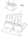
- Fig. 1 shows a schematic representation of a reagent container system comprising a first reagent container 1 cassette and a second reagent container cassette 2 in a storage configuration and a use configuration.
- the reagent container system is first provided, as in upper part of Fig. 1 , in the storage configuration in which longitudinal sides 3, 4 of the first reagent container cassette 1 and the second reagent container cassette 2 are arranged adjacent to one another and touching. Once opened, the reagent container system can be released from the storage configuration and brought into the use configuration shown in the lower part of Fig. 1 . This is achieved by swivelling the second reagent container cassette 2 about a swivelling axis 5 which in turn runs along an edge 6. A film hinge 7 is located at the edge 6.
- the storage configuration can also be called the closed / folded configuration whereas the use configuration is an unfolded / opened configuration of the reagent container cassettes 1,2.
- the reagent container system can be filled with desired reagents, shown with arrow A in Fig. 1 .
- the reagent container system is on a conveyor belt 8 which serves to transport several reagent container systems past a suitable filling apparatus.
- a linear arrangement of openings 9 is provided by arranging transverse sides 10, 11 of the first and second reagent container cassettes 1, 2 facing one another.
- Fig. 2 shows a schematic representation of the reagent container system in Fig. 1 , wherein the first reagent container cassette 1 and the second reagent container cassette 2 are joined by the film hinge 7.
- the reagent container system is shown in a top view.
- Fig. 3 shows a schematic representation of a reagent container system in a top view, wherein a first reagent container cassette 1 and a second reagent container cassette 2 are joined by an adhesive strip 30.
- Fig. 4 shows a schematic representation of a reagent container system in a top view, wherein a first reagent container cassette 1 and a second reagent container cassette 2 are joined by an articulation 40.
- Fig. 5 shows a schematic representation of a reagent container system in a top view, wherein a first reagent container cassette 1 and a second reagent container cassette 2 are joined by snap articulation 50.
- Fig. 6 shows a schematic representation of a reagent container system in a use configuration, wherein a set of openings is implemented by a plurality of recesses 60.
- the recesses 60 are made in the material of the two reagent container cassettes 1, 2 itself.
- Such recesses 60 can be manufactured, with the help of the production of the reagent container system, as injection molded parts
- Fig. 7 shows a schematic representation of a reagent container system in a use configuration, wherein a set of openings is implemented by a plurality of sub containers.
- spaces 70 in the first reagent container cassette 1 and the second reagent container cassette 2 are depicted in which the respective sub containers 71 can be loosely or securely placed.
- the sub containers 71 are made of, for example, plastic or glass and usually take the form of small bottles.
- Fig. 8 shows a schematic representation of a reagent container system, wherein a first reagent container cassette 1 and a second reagent container cassette 2 are fixed in a used configuration by an adhesive strip 80.
- the adhesive strip 80 is attached.
- Fig. 9 shows a schematic representation of a reagent container system, wherein a first reagent container cassette 1 and a second reagent container cassette 2 are fixed in a use configuration by a snap element 90. In the closed state, a projection 91 is at least partially enclosed by the open catch 92.
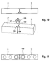
- Fig. 10 shows a schematic representation of a reagent container system, wherein a first reagent container cassette 1 and a second reagent container cassette 2 are fixed in a use configuration by a plug-in element 100.
- the plug-in element 100 has two projections 101, 102 which slot into the allocated recesses 103, 104 in order to secure the first and second reagent container cassettes 1, 2 in the use configuration.
- Fig. 11 shows a schematic representation of a reagent container system, wherein a first reagent container cassette 1 and a second reagent container cassette 2 are fixed in a use configuration by a joining member 110.
- Fig. 12 shows a schematic representation of a reagent container system comprising a first reagent container cassette 1 and a second reagent container cassette 2 in a storage configuration, wherein the reagent container cassettes 1, 2 are secured by an adhesive element 120.
- Fig 13 shows a schematic representation of a reagent container system comprising a first reagent container cassette 1 and a second reagent container cassette 2 in a storage configuration, wherein the reagent container cassettes 1, 2 are secured by a plug-in member 130.
- Fig. 14 shows a schematic representation of a reagent container system comprising a first reagent container cassette 1 and a second reagent container cassette 2 in a storage configuration, wherein the reagent container cassettes 1, 2 are secured by a snap element 140.
- Fig. 15 shows a schematic representation of a reagent container system comprising a first reagent container cassette 1 and a second reagent container cassette 2 in a storage configuration, wherein the reagent container cassettes 1, 2 are secured by a cover element 150.
- Fig. 16 shows a schematic representation of a reagent container system comprising a first reagent container cassette 1 and a second reagent container cassette 2 in a storage configuration, wherein the reagent container cassettes 1, 2 are secured by a foot element 160.
- the two reagent container cassettes 1, 2 are positioned in the foot element 160 and thus secured in the storage configuration.
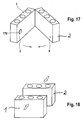
- Fig. 17 shows a schematic representation of a reagent container system comprising a first reagent container cassette 1 and a second reagent container cassette 2, wherein further connecting means 170 are provided on the longitudinal sides 3, 4 facing each other in the storage configuration.
- the further connecting means 170 are provided as an adhesive material.
- a plug-in or a snap connection may be provided.
- Fig. 18 shows a schematic representation of a reagent container system comprising a first reagent container cassette 1 and a second reagent container cassette 2 which are disconnectably joined in the storage configuration after the reagent container cassettes 1, 2 have been filled in the use configuration where the reagent container cassettes 1, 2 are separated from each other.
- the different embodiments of the reagent container system have been described using embodiments where two reagent container cassettes are depicted, namely the first reagent container cassette 1 and the second reagent container cassette 2.
- reagent container cassettes can be combined in a similar way in the reagent container system whereby these can be arranged such that adjacent reagent container cassettes have transverse sides facing in the use configuration and longitudinal sides facing in the storage configuration. Both configurations constitute a closed position and an open position which may also referred to as a fold and an unfold position (configuration), respectively.
- reagent container cassettes can be connected to one another using the connection methods described above so that they are in accordion like formation.
Landscapes
- Chemical & Material Sciences (AREA)
- Chemical Kinetics & Catalysis (AREA)
- Health & Medical Sciences (AREA)
- Analytical Chemistry (AREA)
- Physics & Mathematics (AREA)
- Life Sciences & Earth Sciences (AREA)
- Clinical Laboratory Science (AREA)
- Biochemistry (AREA)
- General Health & Medical Sciences (AREA)
- General Physics & Mathematics (AREA)
- Immunology (AREA)
- Pathology (AREA)
- Automatic Analysis And Handling Materials Therefor (AREA)
- Packages (AREA)
Claims (13)
- Système de conteneur de réactifs destiné à être utilisé dans un analyseur comprenant :- une première cassette de réactifs (1) équipée d'une première série d'orifices (9), chacun pouvant contenir un réactif liquide,- une seconde cassette de réactifs (2) équipée d'une seconde série d'orifices (9), chacun pouvant contenir un réactif liquide, et- un dispositif de fixation comprenant au moins un élément entre une articulation (40) et un pivot, configurés de façon à assembler la première et la seconde cassettes de réactifs (1, 2) au moins dans une configuration de stockage, où, dans la configuration de stockage, la première et la seconde cassettes de réactifs (1, 2) sont assemblées et un côté longitudinal (3) de la première cassette de réactifs (1) fait face à un côté longitudinal (4) de la seconde cassette de réactifs (2),où, grâce à un déplacement relatif, la première et la seconde cassettes de réactifs (1, 2) peuvent être déplacées afin de passer d'une configuration de stockage à une configuration d'utilisation, où un côté transversal (10) de la première cassette de réactifs (1) fait face un côté transversal (11) de la seconde cassette de réactifs (2) en configuration d'utilisation, où le dispositif de fixation est configuré de façon à fournir une jonction entre la première et la seconde cassettes de réactifs (1, 2) en configuration d'utilisation,
où au moins l'une de la première ou de la seconde série d'orifices (9) est mise en place par une pluralité d'alvéoles (60) présentes dans le matériau de la première et de la seconde cassette de réactifs (1, 2), respectivement, où le dispositif de fixation comprend en outre des éléments de connexion (170) sur au moins un côté longitudinal (3) de la première cassette de réactifs (1) et un côté longitudinal (11) de la seconde cassette de réactifs (2), où les éléments de connexion (170) sont configurés de façon à se fixer mutuellement aux côtés longitudinaux adjacents de la première et de la seconde cassettes de réactifs (1, 2) en configuration de stockage, le système de conteneur de réactifs étant caractérisé en ce que les éléments de sécurisation (120, 130, 140, 150, 160) sont en outre fournis, lesdits éléments de sécurisation étant configurés de façon à sécuriser un arrangement relatif de la première et de la seconde cassette de réactifs (1, 2) en configuration de stockage. - Système de conteneur de réactifs selon la revendication 1, dans lequel le côté longitudinal (3) de la première cassette de réactifs (1) est en contact avec le côté longitudinal (4) de la seconde cassette de réactifs (2) en configuration de stockage.
- Système de conteneur de réactifs selon au moins l'une des revendications précédentes, dans lequel le côté transversal (10) de la première cassette de réactifs (1) est en contact avec le côté transversal (11) de la seconde cassette de réactifs (2) en configuration d'utilisation.
- Système de conteneur de réactifs selon l'une des revendications précédentes, dans lequel le dispositif de fixation est fourni sous forme de connexion débrayable.
- Système de conteneur de réactifs selon l'une des revendications précédentes, dans lequel le dispositif de fixation est fourni au niveau d'un coin (5) où, à ce niveau-là, un coin (5) de la première cassette de réactifs (1) et un coin de la seconde cassette de réactifs (2) se font face.
- Système de conteneur de réactifs selon l'une des revendications précédentes, dans lequel les éléments de sécurisation sont fournis et sont configurés de façon à sécuriser un arrangement relatif de la première et de la seconde cassettes de réactifs (1, 2) en configuration d'utilisation.
- Système de conteneur de réactifs selon la revendication 6, dans lequel les éléments de sécurisation comprennent au moins un élément de sécurisation sélectionné dans le groupe d'éléments de sécurisation suivants : élément adhésif (80), mousqueton (90) et élément encastrable (100).
- Système de conteneur de réactifs selon l'une des revendications précédentes, dans lequel les éléments de sécurisation comprennent en outre au moins un élément de sécurisation sélectionné dans le groupe d'éléments de sécurisation suivants : élément adhésif (120), mousqueton (140), élément encastrable (130), élément recouvrant (150) et socle (160).
- Système de conteneur de réactifs selon l'une des revendications précédentes, dans lequel au moins une de la première et de la seconde séries d'orifices (9) est mise en fonction par un ou plusieurs sous-contenants (71) présents dans la première et la seconde cassette de réactifs (1, 2) respectivement.
- Système de conteneur de réactifs selon l'une des revendications précédentes, dans lequel au moins l'une de la première et de la seconde séries d'orifices (9) est fournie sous forme d'orifices alignés.
- Système de conteneur de réactifs selon l'une des revendications précédentes, dans lequel une marque distinctive est présente sur au moins l'une de la première et de la seconde cassettes de réactifs (1, 2).
- Système de conteneur de réactifs selon la revendication 11, dans lequel la marque distinctive est présente sur au moins le côté longitudinal (3) de la première cassette de réactifs (1) et le côté longitudinal (4) de la seconde cassette de réactifs (2).
- Système de conteneur de réactifs selon la revendication 11 ou 12, dans lequel la marque distinctive est recouverte en configuration de stockage.
Priority Applications (1)
| Application Number | Priority Date | Filing Date | Title |
|---|---|---|---|
| EP08802492.2A EP2193378B1 (fr) | 2007-09-28 | 2008-09-22 | Système de conteneurs pour réactifs |
Applications Claiming Priority (3)
| Application Number | Priority Date | Filing Date | Title |
|---|---|---|---|
| EP07019129 | 2007-09-28 | ||
| EP08802492.2A EP2193378B1 (fr) | 2007-09-28 | 2008-09-22 | Système de conteneurs pour réactifs |
| PCT/EP2008/007999 WO2009040082A1 (fr) | 2007-09-28 | 2008-09-22 | Système de réceptacle pour réactifs |
Publications (2)
| Publication Number | Publication Date |
|---|---|
| EP2193378A1 EP2193378A1 (fr) | 2010-06-09 |
| EP2193378B1 true EP2193378B1 (fr) | 2016-11-23 |
Family
ID=39149352
Family Applications (1)
| Application Number | Title | Priority Date | Filing Date |
|---|---|---|---|
| EP08802492.2A Not-in-force EP2193378B1 (fr) | 2007-09-28 | 2008-09-22 | Système de conteneurs pour réactifs |
Country Status (6)
| Country | Link |
|---|---|
| US (1) | US8388913B2 (fr) |
| EP (1) | EP2193378B1 (fr) |
| JP (1) | JP5367713B2 (fr) |
| CN (1) | CN101815948B (fr) |
| CA (1) | CA2700889C (fr) |
| WO (1) | WO2009040082A1 (fr) |
Families Citing this family (13)
| Publication number | Priority date | Publication date | Assignee | Title |
|---|---|---|---|---|
| USD978375S1 (en) * | 2013-03-13 | 2023-02-14 | Abbott Laboratories | Reagent container |
| USD962471S1 (en) | 2013-03-13 | 2022-08-30 | Abbott Laboratories | Reagent container |
| US10058866B2 (en) | 2013-03-13 | 2018-08-28 | Abbott Laboratories | Methods and apparatus to mitigate bubble formation in a liquid |
| US9535082B2 (en) | 2013-03-13 | 2017-01-03 | Abbott Laboratories | Methods and apparatus to agitate a liquid |
| GB201322082D0 (en) * | 2013-12-13 | 2014-01-29 | Ge Healthcare Bio Sciences Ab | Floatable microplate |
| CN105032521A (zh) * | 2015-06-02 | 2015-11-11 | 烟台海深威医学技术有限公司 | 多功能折叠试管架 |
| CN105772140B (zh) * | 2016-04-27 | 2018-07-31 | 安徽理工大学 | 一种综合比色管架 |
| CN112888505A (zh) * | 2018-08-22 | 2021-06-01 | 奎斯特诊断投资有限责任公司 | 用于采样设备的板和用于微量采样设备的微量离心管 |
| US11992845B2 (en) | 2018-12-14 | 2024-05-28 | Leica Biosystems Melbourne Pty Ltd | Reagent cassette |
| WO2022038269A1 (fr) * | 2020-08-20 | 2022-02-24 | Danmarks Tekniske Universitet | Procédés, ensemble et système de surveillance parallèle à haut rendement de systèmes de réaction |
| KR102582314B1 (ko) * | 2023-05-12 | 2023-09-26 | (주)에이티솔루션즈 | 폴더블 튜브랙 |
| US20250187015A1 (en) * | 2023-12-06 | 2025-06-12 | Dionex Corporation | Segmented trays for autosampler |
| DE102024120604A1 (de) | 2024-07-19 | 2026-01-22 | Analytik Jena Gmbh+Co. Kg | System zum Erzeugen von Trägerplatten für Medien oder Teilmodule und entsprechende Trägerplatte |
Citations (5)
| Publication number | Priority date | Publication date | Assignee | Title |
|---|---|---|---|---|
| GB2145695A (en) * | 1983-09-01 | 1985-04-03 | Mead Corp | Divisible article tray |
| JPS6198534U (fr) * | 1984-12-05 | 1986-06-24 | ||
| JPH11123335A (ja) * | 1997-10-22 | 1999-05-11 | Ir Medical:Kk | 試験管立て |
| JP2002028503A (ja) * | 2000-07-13 | 2002-01-29 | Shinsei Industries Co Ltd | 多連式試験管立て |
| FR2873447A1 (fr) * | 2004-07-23 | 2006-01-27 | Alain Michel Rousseau | Analyseur automatique pluridisciplinaire pour le diagnostic in vitro |
Family Cites Families (12)
| Publication number | Priority date | Publication date | Assignee | Title |
|---|---|---|---|---|
| JPS5453493A (en) * | 1977-10-01 | 1979-04-26 | Masaaki Kusano | Method of transport by aircraft |
| JPS5456493A (en) * | 1977-10-05 | 1979-05-07 | Agency Of Ind Science & Technol | Sample rack mechanism for continuous analysis of multiple specimens |
| JPS56137072U (fr) * | 1980-03-17 | 1981-10-17 | ||
| US4925630A (en) * | 1989-05-16 | 1990-05-15 | Grunwald James L | Sample vials tray |
| AU665853B2 (en) * | 1992-06-29 | 1996-01-18 | Dade International Inc. | Sample tube carrier |
| DE4425277A1 (de) * | 1994-07-16 | 1996-01-18 | Boehringer Mannheim Gmbh | Verpackungssystem für Flüssigreagenzien |
| DE29502834U1 (de) * | 1995-02-21 | 1995-04-06 | Eppendorf-Netheler-Hinz GmbH, 22339 Hamburg | Halter für Laborgefäße |
| JPH09127137A (ja) * | 1995-10-31 | 1997-05-16 | Sanyo Electric Co Ltd | 分注装置 |
| US20050013745A1 (en) * | 2001-12-07 | 2005-01-20 | Buchanan Kristopher S. | Extendable segmented sample carrier system |
| JP2005164509A (ja) | 2003-12-05 | 2005-06-23 | Hitachi High-Technologies Corp | 試薬容器 |
| GB0425786D0 (en) * | 2004-11-24 | 2004-12-22 | Dubois Ltd | Packaging article |
| EP1808698A1 (fr) * | 2006-01-13 | 2007-07-18 | F.Hoffmann-La Roche Ag | Kit de réactif et analyseur |
-
2008
- 2008-09-22 WO PCT/EP2008/007999 patent/WO2009040082A1/fr not_active Ceased
- 2008-09-22 CA CA2700889A patent/CA2700889C/fr not_active Expired - Fee Related
- 2008-09-22 EP EP08802492.2A patent/EP2193378B1/fr not_active Not-in-force
- 2008-09-22 JP JP2010526202A patent/JP5367713B2/ja not_active Expired - Fee Related
- 2008-09-22 CN CN200880109424.4A patent/CN101815948B/zh not_active Expired - Fee Related
-
2010
- 2010-03-26 US US12/732,236 patent/US8388913B2/en not_active Expired - Fee Related
Patent Citations (5)
| Publication number | Priority date | Publication date | Assignee | Title |
|---|---|---|---|---|
| GB2145695A (en) * | 1983-09-01 | 1985-04-03 | Mead Corp | Divisible article tray |
| JPS6198534U (fr) * | 1984-12-05 | 1986-06-24 | ||
| JPH11123335A (ja) * | 1997-10-22 | 1999-05-11 | Ir Medical:Kk | 試験管立て |
| JP2002028503A (ja) * | 2000-07-13 | 2002-01-29 | Shinsei Industries Co Ltd | 多連式試験管立て |
| FR2873447A1 (fr) * | 2004-07-23 | 2006-01-27 | Alain Michel Rousseau | Analyseur automatique pluridisciplinaire pour le diagnostic in vitro |
Also Published As
| Publication number | Publication date |
|---|---|
| JP5367713B2 (ja) | 2013-12-11 |
| EP2193378A1 (fr) | 2010-06-09 |
| CN101815948B (zh) | 2014-03-26 |
| US8388913B2 (en) | 2013-03-05 |
| JP2011510263A (ja) | 2011-03-31 |
| US20100233036A1 (en) | 2010-09-16 |
| HK1147803A1 (en) | 2011-08-19 |
| CA2700889A1 (fr) | 2009-04-02 |
| WO2009040082A1 (fr) | 2009-04-02 |
| CN101815948A (zh) | 2010-08-25 |
| CA2700889C (fr) | 2014-02-11 |
Similar Documents
| Publication | Publication Date | Title |
|---|---|---|
| EP2193378B1 (fr) | Système de conteneurs pour réactifs | |
| US8146627B2 (en) | Easy load pillbox and loading tray | |
| CN106970236B (zh) | 样品试管架和样品试管分析系统 | |
| CN102958546B (zh) | 盒子、用于标记容纳液体的容器的工作台和方法 | |
| JP3191150B2 (ja) | 採血管ラック | |
| US4278225A (en) | Inclined vial holder | |
| US5009316A (en) | Test tube cassette system and cassettes for use therein | |
| EP3946107B1 (fr) | Appareil à râtelier pour tubes | |
| EP3639040B1 (fr) | Dispositif et procédé pour la manutention de tubes de test | |
| US4207289A (en) | Sample tube holder | |
| US8944710B2 (en) | Container for a plurality of disposable applicators comprising a reservoir for a substance to be applied | |
| ES2716632T3 (es) | Soporte de recipientes de muestras, método para bloquear recipientes de muestras en un soporte de recipientes de muestras y sistema de soporte de recipientes de muestras | |
| JP2007187666A (ja) | 試薬キットおよび分析装置 | |
| US5916527A (en) | Convertible stand and container and method | |
| EP1895305A1 (fr) | Association de conteneurs de reactifs | |
| JP2009544942A (ja) | スライド処理用トレイ | |
| US20210077222A1 (en) | Interchangeable labelling plate | |
| US20060254950A1 (en) | Medicine bottle organizer for home/travel | |
| US6640995B2 (en) | Contact lens dispensing system | |
| WO2017195910A1 (fr) | Dispositif d'emballage de livres également utilisable en tant que bibliothèque et procédé associé | |
| EP4506061A1 (fr) | Support d'échantillons modulaire | |
| CN209650956U (zh) | 一种医疗透析器存放设备 | |
| JP3036058U (ja) | 缶飲料用の商品サンプル |
Legal Events
| Date | Code | Title | Description |
|---|---|---|---|
| PUAI | Public reference made under article 153(3) epc to a published international application that has entered the european phase |
Free format text: ORIGINAL CODE: 0009012 |
|
| 17P | Request for examination filed |
Effective date: 20100323 |
|
| AK | Designated contracting states |
Kind code of ref document: A1 Designated state(s): AT BE BG CH CY CZ DE DK EE ES FI FR GB GR HR HU IE IS IT LI LT LU LV MC MT NL NO PL PT RO SE SI SK TR |
|
| AX | Request for extension of the european patent |
Extension state: AL BA MK RS |
|
| DAX | Request for extension of the european patent (deleted) | ||
| 17Q | First examination report despatched |
Effective date: 20140515 |
|
| REG | Reference to a national code |
Ref country code: DE Ref legal event code: R079 Ref document number: 602008047541 Country of ref document: DE Free format text: PREVIOUS MAIN CLASS: G01N0035100000 Ipc: B01L0009060000 |
|
| GRAP | Despatch of communication of intention to grant a patent |
Free format text: ORIGINAL CODE: EPIDOSNIGR1 |
|
| RIC1 | Information provided on ipc code assigned before grant |
Ipc: B01L 9/06 20060101AFI20160606BHEP Ipc: G01N 35/02 20060101ALI20160606BHEP |
|
| INTG | Intention to grant announced |
Effective date: 20160705 |
|
| GRAS | Grant fee paid |
Free format text: ORIGINAL CODE: EPIDOSNIGR3 |
|
| GRAA | (expected) grant |
Free format text: ORIGINAL CODE: 0009210 |
|
| AK | Designated contracting states |
Kind code of ref document: B1 Designated state(s): AT BE BG CH CY CZ DE DK EE ES FI FR GB GR HR HU IE IS IT LI LT LU LV MC MT NL NO PL PT RO SE SI SK TR |
|
| RAP1 | Party data changed (applicant data changed or rights of an application transferred) |
Owner name: F. HOFFMANN-LA ROCHE AG Owner name: ROCHE DIAGNOSTICS GMBH |
|
| REG | Reference to a national code |
Ref country code: GB Ref legal event code: FG4D |
|
| REG | Reference to a national code |
Ref country code: CH Ref legal event code: EP |
|
| REG | Reference to a national code |
Ref country code: IE Ref legal event code: FG4D |
|
| REG | Reference to a national code |
Ref country code: AT Ref legal event code: REF Ref document number: 847378 Country of ref document: AT Kind code of ref document: T Effective date: 20161215 |
|
| REG | Reference to a national code |
Ref country code: DE Ref legal event code: R096 Ref document number: 602008047541 Country of ref document: DE |
|
| PG25 | Lapsed in a contracting state [announced via postgrant information from national office to epo] |
Ref country code: LV Free format text: LAPSE BECAUSE OF FAILURE TO SUBMIT A TRANSLATION OF THE DESCRIPTION OR TO PAY THE FEE WITHIN THE PRESCRIBED TIME-LIMIT Effective date: 20161123 |
|
| REG | Reference to a national code |
Ref country code: LT Ref legal event code: MG4D |
|
| REG | Reference to a national code |
Ref country code: NL Ref legal event code: MP Effective date: 20161123 |
|
| REG | Reference to a national code |
Ref country code: AT Ref legal event code: MK05 Ref document number: 847378 Country of ref document: AT Kind code of ref document: T Effective date: 20161123 |
|
| PG25 | Lapsed in a contracting state [announced via postgrant information from national office to epo] |
Ref country code: NL Free format text: LAPSE BECAUSE OF FAILURE TO SUBMIT A TRANSLATION OF THE DESCRIPTION OR TO PAY THE FEE WITHIN THE PRESCRIBED TIME-LIMIT Effective date: 20161123 Ref country code: GR Free format text: LAPSE BECAUSE OF FAILURE TO SUBMIT A TRANSLATION OF THE DESCRIPTION OR TO PAY THE FEE WITHIN THE PRESCRIBED TIME-LIMIT Effective date: 20170224 Ref country code: LT Free format text: LAPSE BECAUSE OF FAILURE TO SUBMIT A TRANSLATION OF THE DESCRIPTION OR TO PAY THE FEE WITHIN THE PRESCRIBED TIME-LIMIT Effective date: 20161123 Ref country code: NO Free format text: LAPSE BECAUSE OF FAILURE TO SUBMIT A TRANSLATION OF THE DESCRIPTION OR TO PAY THE FEE WITHIN THE PRESCRIBED TIME-LIMIT Effective date: 20170223 Ref country code: SE Free format text: LAPSE BECAUSE OF FAILURE TO SUBMIT A TRANSLATION OF THE DESCRIPTION OR TO PAY THE FEE WITHIN THE PRESCRIBED TIME-LIMIT Effective date: 20161123 |
|
| PG25 | Lapsed in a contracting state [announced via postgrant information from national office to epo] |
Ref country code: FI Free format text: LAPSE BECAUSE OF FAILURE TO SUBMIT A TRANSLATION OF THE DESCRIPTION OR TO PAY THE FEE WITHIN THE PRESCRIBED TIME-LIMIT Effective date: 20161123 Ref country code: PT Free format text: LAPSE BECAUSE OF FAILURE TO SUBMIT A TRANSLATION OF THE DESCRIPTION OR TO PAY THE FEE WITHIN THE PRESCRIBED TIME-LIMIT Effective date: 20170323 Ref country code: AT Free format text: LAPSE BECAUSE OF FAILURE TO SUBMIT A TRANSLATION OF THE DESCRIPTION OR TO PAY THE FEE WITHIN THE PRESCRIBED TIME-LIMIT Effective date: 20161123 Ref country code: HR Free format text: LAPSE BECAUSE OF FAILURE TO SUBMIT A TRANSLATION OF THE DESCRIPTION OR TO PAY THE FEE WITHIN THE PRESCRIBED TIME-LIMIT Effective date: 20161123 Ref country code: ES Free format text: LAPSE BECAUSE OF FAILURE TO SUBMIT A TRANSLATION OF THE DESCRIPTION OR TO PAY THE FEE WITHIN THE PRESCRIBED TIME-LIMIT Effective date: 20161123 Ref country code: PL Free format text: LAPSE BECAUSE OF FAILURE TO SUBMIT A TRANSLATION OF THE DESCRIPTION OR TO PAY THE FEE WITHIN THE PRESCRIBED TIME-LIMIT Effective date: 20161123 |
|
| PG25 | Lapsed in a contracting state [announced via postgrant information from national office to epo] |
Ref country code: DK Free format text: LAPSE BECAUSE OF FAILURE TO SUBMIT A TRANSLATION OF THE DESCRIPTION OR TO PAY THE FEE WITHIN THE PRESCRIBED TIME-LIMIT Effective date: 20161123 Ref country code: SK Free format text: LAPSE BECAUSE OF FAILURE TO SUBMIT A TRANSLATION OF THE DESCRIPTION OR TO PAY THE FEE WITHIN THE PRESCRIBED TIME-LIMIT Effective date: 20161123 Ref country code: RO Free format text: LAPSE BECAUSE OF FAILURE TO SUBMIT A TRANSLATION OF THE DESCRIPTION OR TO PAY THE FEE WITHIN THE PRESCRIBED TIME-LIMIT Effective date: 20161123 Ref country code: CZ Free format text: LAPSE BECAUSE OF FAILURE TO SUBMIT A TRANSLATION OF THE DESCRIPTION OR TO PAY THE FEE WITHIN THE PRESCRIBED TIME-LIMIT Effective date: 20161123 Ref country code: EE Free format text: LAPSE BECAUSE OF FAILURE TO SUBMIT A TRANSLATION OF THE DESCRIPTION OR TO PAY THE FEE WITHIN THE PRESCRIBED TIME-LIMIT Effective date: 20161123 |
|
| REG | Reference to a national code |
Ref country code: DE Ref legal event code: R097 Ref document number: 602008047541 Country of ref document: DE |
|
| PG25 | Lapsed in a contracting state [announced via postgrant information from national office to epo] |
Ref country code: IT Free format text: LAPSE BECAUSE OF FAILURE TO SUBMIT A TRANSLATION OF THE DESCRIPTION OR TO PAY THE FEE WITHIN THE PRESCRIBED TIME-LIMIT Effective date: 20161123 Ref country code: BG Free format text: LAPSE BECAUSE OF FAILURE TO SUBMIT A TRANSLATION OF THE DESCRIPTION OR TO PAY THE FEE WITHIN THE PRESCRIBED TIME-LIMIT Effective date: 20170223 Ref country code: BE Free format text: LAPSE BECAUSE OF FAILURE TO SUBMIT A TRANSLATION OF THE DESCRIPTION OR TO PAY THE FEE WITHIN THE PRESCRIBED TIME-LIMIT Effective date: 20161123 |
|
| PLBE | No opposition filed within time limit |
Free format text: ORIGINAL CODE: 0009261 |
|
| STAA | Information on the status of an ep patent application or granted ep patent |
Free format text: STATUS: NO OPPOSITION FILED WITHIN TIME LIMIT |
|
| 26N | No opposition filed |
Effective date: 20170824 |
|
| PG25 | Lapsed in a contracting state [announced via postgrant information from national office to epo] |
Ref country code: SI Free format text: LAPSE BECAUSE OF FAILURE TO SUBMIT A TRANSLATION OF THE DESCRIPTION OR TO PAY THE FEE WITHIN THE PRESCRIBED TIME-LIMIT Effective date: 20161123 |
|
| REG | Reference to a national code |
Ref country code: DE Ref legal event code: R119 Ref document number: 602008047541 Country of ref document: DE |
|
| REG | Reference to a national code |
Ref country code: CH Ref legal event code: PL |
|
| GBPC | Gb: european patent ceased through non-payment of renewal fee |
Effective date: 20170922 |
|
| PG25 | Lapsed in a contracting state [announced via postgrant information from national office to epo] |
Ref country code: MC Free format text: LAPSE BECAUSE OF FAILURE TO SUBMIT A TRANSLATION OF THE DESCRIPTION OR TO PAY THE FEE WITHIN THE PRESCRIBED TIME-LIMIT Effective date: 20161123 |
|
| REG | Reference to a national code |
Ref country code: IE Ref legal event code: MM4A |
|
| PG25 | Lapsed in a contracting state [announced via postgrant information from national office to epo] |
Ref country code: LU Free format text: LAPSE BECAUSE OF NON-PAYMENT OF DUE FEES Effective date: 20170922 |
|
| REG | Reference to a national code |
Ref country code: FR Ref legal event code: ST Effective date: 20180531 |
|
| PG25 | Lapsed in a contracting state [announced via postgrant information from national office to epo] |
Ref country code: GB Free format text: LAPSE BECAUSE OF NON-PAYMENT OF DUE FEES Effective date: 20170922 Ref country code: DE Free format text: LAPSE BECAUSE OF NON-PAYMENT OF DUE FEES Effective date: 20180404 Ref country code: LI Free format text: LAPSE BECAUSE OF NON-PAYMENT OF DUE FEES Effective date: 20170930 Ref country code: IE Free format text: LAPSE BECAUSE OF NON-PAYMENT OF DUE FEES Effective date: 20170922 Ref country code: CH Free format text: LAPSE BECAUSE OF NON-PAYMENT OF DUE FEES Effective date: 20170930 |
|
| PG25 | Lapsed in a contracting state [announced via postgrant information from national office to epo] |
Ref country code: FR Free format text: LAPSE BECAUSE OF NON-PAYMENT OF DUE FEES Effective date: 20171002 |
|
| PG25 | Lapsed in a contracting state [announced via postgrant information from national office to epo] |
Ref country code: MT Free format text: LAPSE BECAUSE OF NON-PAYMENT OF DUE FEES Effective date: 20170922 |
|
| PG25 | Lapsed in a contracting state [announced via postgrant information from national office to epo] |
Ref country code: HU Free format text: LAPSE BECAUSE OF FAILURE TO SUBMIT A TRANSLATION OF THE DESCRIPTION OR TO PAY THE FEE WITHIN THE PRESCRIBED TIME-LIMIT; INVALID AB INITIO Effective date: 20080922 |
|
| PG25 | Lapsed in a contracting state [announced via postgrant information from national office to epo] |
Ref country code: CY Free format text: LAPSE BECAUSE OF NON-PAYMENT OF DUE FEES Effective date: 20161123 |
|
| PG25 | Lapsed in a contracting state [announced via postgrant information from national office to epo] |
Ref country code: TR Free format text: LAPSE BECAUSE OF FAILURE TO SUBMIT A TRANSLATION OF THE DESCRIPTION OR TO PAY THE FEE WITHIN THE PRESCRIBED TIME-LIMIT Effective date: 20161123 |
|
| PG25 | Lapsed in a contracting state [announced via postgrant information from national office to epo] |
Ref country code: IS Free format text: LAPSE BECAUSE OF FAILURE TO SUBMIT A TRANSLATION OF THE DESCRIPTION OR TO PAY THE FEE WITHIN THE PRESCRIBED TIME-LIMIT Effective date: 20170323 |