EP2206330B1 - Übertragung von breitbandsignalen - Google Patents
Übertragung von breitbandsignalen Download PDFInfo
- Publication number
- EP2206330B1 EP2206330B1 EP08806509A EP08806509A EP2206330B1 EP 2206330 B1 EP2206330 B1 EP 2206330B1 EP 08806509 A EP08806509 A EP 08806509A EP 08806509 A EP08806509 A EP 08806509A EP 2206330 B1 EP2206330 B1 EP 2206330B1
- Authority
- EP
- European Patent Office
- Prior art keywords
- signals
- emphasis
- broadband
- region
- link
- Prior art date
- Legal status (The legal status is an assumption and is not a legal conclusion. Google has not performed a legal analysis and makes no representation as to the accuracy of the status listed.)
- Active
Links
Images


Classifications
-
- H—ELECTRICITY
- H04—ELECTRIC COMMUNICATION TECHNIQUE
- H04M—TELEPHONIC COMMUNICATION
- H04M11/00—Telephonic communication systems specially adapted for combination with other electrical systems
- H04M11/06—Simultaneous speech and data transmission, e.g. telegraphic transmission over the same conductors
- H04M11/062—Simultaneous speech and data transmission, e.g. telegraphic transmission over the same conductors using different frequency bands for speech and other data
-
- H—ELECTRICITY
- H04—ELECTRIC COMMUNICATION TECHNIQUE
- H04B—TRANSMISSION
- H04B10/00—Transmission systems employing electromagnetic waves other than radio-waves, e.g. infrared, visible or ultraviolet light, or employing corpuscular radiation, e.g. quantum communication
- H04B10/50—Transmitters
- H04B10/58—Compensation for non-linear transmitter output
-
- Y—GENERAL TAGGING OF NEW TECHNOLOGICAL DEVELOPMENTS; GENERAL TAGGING OF CROSS-SECTIONAL TECHNOLOGIES SPANNING OVER SEVERAL SECTIONS OF THE IPC; TECHNICAL SUBJECTS COVERED BY FORMER USPC CROSS-REFERENCE ART COLLECTIONS [XRACs] AND DIGESTS
- Y02—TECHNOLOGIES OR APPLICATIONS FOR MITIGATION OR ADAPTATION AGAINST CLIMATE CHANGE
- Y02D—CLIMATE CHANGE MITIGATION TECHNOLOGIES IN INFORMATION AND COMMUNICATION TECHNOLOGIES [ICT], I.E. INFORMATION AND COMMUNICATION TECHNOLOGIES AIMING AT THE REDUCTION OF THEIR OWN ENERGY USE
- Y02D30/00—Reducing energy consumption in communication networks
- Y02D30/50—Reducing energy consumption in communication networks in wire-line communication networks, e.g. low power modes or reduced link rate
Definitions
- the present invention is concerned with the transmission of broadband signals onto to a telephony connection, in particular in situations in which the signal levels that can be transmitted over the telephony connection are limited as a function of frequency by a constraint profile.
- ADSL Asymmetrical Digital Subscriber Line
- An alternative proposal, providing higher data rates, is to make use of the copper pair only from some point rather closer to the user, normally from the intermediate node or cabinet connected to the exchange by an optical link. This is sometimes referred to as a “fibre to the cabinet” arrangement, and is used with very high speed Digital Subscriber Line (VDSL) technology or other Digital Subscriber Line technologies, which are generally referred to as "xDSL”.
- VDSL Digital Subscriber Line
- xDSL signals produced using xDSL modulation (rather than SDH or ATM techniques) are referred to herein as “broadband signals” and are discussed further in appendix 1.
- a broadband service is provided from the exchange by a multiplexer/demultiplexer which multiplexes signals, using ATM or SDH techniques, onto one or more optical fibres that feed the cabinet.
- a multiplexer/demultiplexer which multiplexes signals, using ATM or SDH techniques, onto one or more optical fibres that feed the cabinet.
- Within the cabinet there is provided (for each fibre) an ATM or SDH demultiplexer, and at least one DSL access multiplexer (DSLAM) for providing, on the basis of the demultiplexed ATM or SDH signals, broadband signals suitable for travelling over the copper pairs, which ultimately lead to the subscriber premises.
- the or each xDSL modem is connected via filters to the copper pairs so that the broadband signals can be carried over a different frequency range to that of the telephony signals, without the telephony signals and the broadband signals affecting one another.
- a power supply is normally provided in the cabinet to supply power to the various optical/electrical components.
- Each line has a constraint profile associated therewith (know empirically from tests on the line), specifying the maximum allowed power at each frequency.
- a constraint profile will have at least one spectral region in which the allowed spectral power is diminished relative to adjacent regions.
- GB 2 383 919 describes line extender equipment for extending the range of an electrical telephone line carrying normal telephony signals together with digital subscriber line broadband signals.
- the line extension is performed using an optical fibre.
- the telephony and broadband signals are pre-emphasised at a first interface to attenuate signals in the band from dc to 100 Hz by 34 dB relative to signals with a frequency of 300 Hz and Higher.
- a second interface converts the optical signals into electrical signals and de-emphasise the electrical signals such that the electrical signals are suitable for driving an electrical telephone line.
- US 2002/0031113 describes an arrangement in which digital subscriber line signals are removed from a metallic telephone line and communicated between a field cabinet and a central office using fiber optic broadband transmission while plain old telephone service signals flow along the metallic telephone line in an undisturbed manner.
- the broadband signals are returned to the levels within those specified by the constraint profile, the broadband signal can be more safely transmitted over the telephony connection.
- the analogue-to-digital conversion process is preferably a low resolution process having 10 12 levels or less. Although this introduces significant noise, the pre-emphasis, which is performed before the noise is introduced, improves the signal to noise ratio. Since de-emphasis is performed on the broadband signal with the noise therein, the signal to noise ratio is preserved in the pre-emphasis band, that is, in the second spectral region.
- a method of delivering broadband signals over an optical link for subsequent transport over a telephony connection including the steps of: performing pre-emphasis on the broadband signals; converting the broadband signals from the electrical domain into the optical domain; transmitting the converted broadband signals over the optical link; after transmission over an optical link, converting the broadband signals from the optical domain back into the electrical domain; performing de-emphasis on the transmitted broadband signals; and, transmitting the de-emphasised signals onto the telephony connection.
- the steps of converting the broadband signals from the electrical domain into the optical domain and of converting the broadband signals from the optical domain back into the electrical domain are carried out using a conversion process having a noise level associated therewith in a given spectral region.
- the pre-emphasis preferably has the effect of increasing the broadband signals relative to the noise floor in the given spectral region, and the de-emphasis preferably has the effect of decreasing the both the broadband signal and the noise level in the given spectral region.
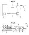
- FIG. 1 shows a telecommunications system 10 in which conventional telephony signals from an exchange 12 are fed to an intermediate node, here a cabinet 14, over an E-slde (Exchange-side) electrical connection 16.
- the telephony signals are then relayed to a customer terminal (such as a telephone system) 18 over a D-side (Distribution-side) electrical connection 20, formed by a twisted pair of electrical conductors, normally from copper conductors.
- twisted pair conductors it is meant a pair of conducting wires, insulated from one another, which cross one another at spaced apart locations along the their length.
- the cabinet will be connected to a plurality of terminals 18, each over a respective one of a plurality of twisted pair conductors, although these are not shown for clarity.
- the E-side and D-side connections are part of a conventional telephony network, the D-side connections ranging in length from a few meters to several kilometres.
- the exchange 12 includes a modem equipment in the form of a Digital Subscriber Line Access Modem (DSLAM) 22, hereinafter referred to as a modem, for modulating or otherwise converting SDH-modulated signals from a network input into broadband signals that can be carried by the twisted pair conductors over practical distances, typically over 1km.
- DSLAM Digital Subscriber Line Access Modem
- the customer terminal also includes a equipment (not shown) for demodulating the downstream signals from the DSLAM, and for modulating upstream signals.
- broadband signals are formed as a plurality of tones, each individually modulated according to Quadrature Amplitude Modulation.
- the modem is arranged to determine the number and relative amplitude of the transmitted tones by a feedback process, in dependence on the characteristics of the particular line over which the tones are carried.
- the resulting superposition of tones appears as an analogue signal.
- Such an arrangement is required because a twisted pair conductor is generally inefficient at carrying high frequency signals, resulting in significant loss and cross-talk with adjacent twisted pair conductors, which may be located in the same conduit.
- the broadband signals from the modem are carried by an optical connection, here an optical fibre 23, to an optical node 24, where the signals are then relayed as electrical signals to the cabinet 14 (that is, the signals in the optical domain are converted into the electrical domain by a conversion circuit).
- the broadband signals are superposed as electrical signals onto the telephony signals and are transmitted over the E-side twisted pair conductor 20 to the customer terminal 18.
- Superposition of the telephony and broadband signals is possible because the two signals reside in different frequency ranges, conventional telephony signals having a range of about 400Hz to 3kHz, whilst broadband signals typically have a range of 0.1 MHz to 10 MHz.
- FIG 2 A more detailed view of the opto-electronic route between the modem 22 and the cabinet 14 is provided in figure 2 , in which components corresponding to those of figure 1 have corresponding numerals.
- Electrical broadband signals from the modem 22 are passed to a pre-emphasis stage 26 where the electrical signals are subjected to frequency dependent gain, so as to provide shaping of the signals in the frequency domain.
- the pre-emphasise stage can be described by a frequency dependent gain function G(f), where f is the frequency.
- the so-shaped electrical signal is then converted into a binary or other digital signal by an analogue to digital (A/D) converter stage 28, before being converted into the optical domain by a transmission stage 30.
- the transmitter, A/D converter, pre-emphasise stage, and the modem are each shown as being within the exchange 22, but may be distributed outside the exchange. It is beneficial to transmit the signal along the optical fibre 23 in digital form because the error or noise introduced in the transmission process can more easily and more reliably be predicted than with analogue transmission. This is because even a small non linearity often present in analogue systems would produce harmonics which would interfere with higher frequency tones.
- the A/D converter has access to encoding and serialisation means to allow the signal to be transmitted in serial fashion over the optical fibre. Likewise, the D/A converter has access to decoding and de-serialisation means in order to properly process the incoming signal.
- the optical signals are converted back into the electrical domain by a receiver stage 32 and passed to a Digital-Analogue (D/A) converter 34.
- D/A Digital-Analogue
- the signals are then processed by a de-emphasis stage 36, where the frequency-shaping applied by the pre-emphasise stage 26 is reversed.
- the de-emphasised signal is then passed to the cabinet 14 for transmission over the twisted pair conductor 20.
- Each of the pre-emphasis and de-emphasis stages are implemented using respective processor means arranged to execute appropriate signal-processing routines stored on respective memory means.
- the pre-emphasise and de-emphasis is carried out in order to address conflicting demands.
- One of the demands results from the desire to limit the power dissipation at the optical node. This is to reduce the need for environmental control at the optical node, and make it easier to power the optical node using power from the cabinet 14, i.e., using power transmitted over the telephony network (in particular the E-side telephony connection 16).
- a reduced power consumption is achieved, in part, by using an A/D and D/A conversion scheme that uses only coarse quantisation. For example, in the present embodiment, a quantisation scheme having 2 10 levels is used, although 2 11 or 2 12 levels could be used instead.
- the sampling rate of the A/D conversion is kept as low as possible. In practice, this means that the sampling rate is twice the frequency of the highest frequency component in the broadband signal: that is, the signal is sampled at the Nyquist frequency, rather than at a higher frequency as is normally done to reduce noise.
- the curve has three regions: a first region (i); a second region (ii); and, a third region (iii).
- the second region which is between the first and third regions in frequency, is a low power region, the first and third regions being high power regions. That is, the power level of the second region is, at least on average over the frequency range of the second region, lower than the power levels of the first and third regions.
- noise floor NF
- the noise floor is shown as a perfectly straight line, the noise floor is likely to have some frequency dependence, but this will generally be limited to 50% of its value, at least within the frequency range of the second region, but preferably in the broadband signal range of 0.1 MHz to 10MHz.
- the gain function G(f) is shaped so that, broadly speaking, the gain function has a high region in the frequency range corresponding to the low power region (ii) of the constraint curve and low regions in high power regions of the constraint curve, as illustrated in figure 3b .
- the broadband signal can be viewed as being conceptually divided into a plurality of bands illustrated by the regions (i),(ii) and (iii), the pre-emphasis stage being arranged to apply a different gain (if any) to the different bands.
- the gain function can be viewed as a gain profile, and the effect of the pre-emphasis stage can be viewed a filter or an amplifier which has a lower gain, if any, in the first and third regions than in the second region.
- the de-emphasis stage can also be viewed as an amplifier or a filter with a frequency-dependent gain profile.
- the difference between the signal level (amplitude) in the low power region (ii) and the high power regions (i), (iii) is reduced.
- the noise floor is unaffected by the pre-emphasise.
- the SNR in the low.power region (ii) is increased.
- the SNR is reduced in the high power regions of the constraint curve, but this reduction can be tolerated because the SNR was originally high in those regions.
- the function R(f) describing the de-emphasis, through which the pre-emphasise is reversed, is shown in figure 3d . It can be seen that the function R(f) is a gain profile with a depressed region corresponding in frequency to the increased region (ii) of the pre-emphasise curve of figure 3b .
- the output from the de-emphasis stage is shown in figure 3e . Due to the depressed region of the de-emphasis function, the broadband signal is returned to having the constraint profile of figure 3a . That is, in the de-emphasis, the signal level is increased further in the high regions (i), (iii) relative to the level in the low region (ii).
- the de-emphasise is carried out on both the noise and the signal.
- the result of this is that the noise floor is no longer flat, but is reduced in the low region (ii) relative to the high regions (i), (iii). Consequently, the improvement in SNR brought about by the pre-emphasise (in the low region (ii)) is retained, even after de-emphasis.
- the reduction in SNR in the high power regions (i), (iii) is also of course retained, but, as explained above, this is not important because the SNR is already good in those regions.
- the SNR in the broadband signal can be kept to acceptable levels, in particular in the depressed-frequency region of the constraint curve. Furthermore, the signal level transmitted onto the D-side electrical connection 20 remains within the limits specified by the constraint curve of figure 3a , as required by the Access Network Frequency Plan.
- Such signal profiles may have a plurality of depressed regions, in which case the gain function may have a plurality of raised regions, each raised region corresponding in frequency to a respective depressed frequency region of the constraint profile.
- the pre-emphasis stage is arranged to apply a gain of 5dB in region (ii), and to apply no gain to regions (i) and (iii).
- the de-emphasis stage is arranged to apply a gain in region (ii) that is 5dB lower in region (ii) than in regions (i) and (iii).
- different pairs of gain profiles could be used, including ones in which the gain changes smoothly between different regions, provided that for a given pair, the two profiles are complementary to one another: that is, the sum of the two (logarithmic) profiles is substantially frequency independent in the spectral regions of interest.
- the gain profile of the pre-emphasis stage (and the complementary gain profile of the de-emphasis stage) is predetermined before the signal from the modem is received, rather than being a function of the instantaneous incoming signal. That is, the difference or differences in the gain applied to different frequency regions is kept constant as a function of time.
- the pre-emphasis stage may be arrange to dynamically adjust the dynamic range of the signal as a whole, independent of the frequency distribution, in order to avoid clipping at the A/D converter.
- the modem is arranged to store at least one constrain curve in a memory 38.
- the modem will normally store a plurality of constraint curves, each associated with a respective CAL value.
- Input means 40 may be provided to input a CAL value, the modem being arranged to retrieve the appropriate constraint curve for that CAL value.
- the selected constraint curve will then place a predetermined upper bound on the power that can be transmitted at a given frequency, or more precisely, an upper bound on the power that can be transmitted in an incremental frequency range centred at a given frequency for a range of frequencies.
- Figures 4a and 4b show actual constraint curves (dark lines) for a CAL value of 36dB, without and with pre-emphasis, respectively.
- the vertical axis is expressed in terms of Power Spectral Density (PSD).
- PSD Power Spectral Density
- the low power region corresponding to the region of pre-emphasis between 0.17Mhz and 1Mhz is a region in which the power level is not flat, but reduces continuously.
- the gain functions for the pre-emphasis and de-emphasis is shown in figures 5a and 5b respectively.
- the result of the pre-emphasis gain will be to increase signals at the level of the constraint curve to a level in excess of the constraint curve.
- the low power region in the constraint curve (corresponding to region (ii) of figure 3 ) does not have a well defined boundary itself. Nevertheless, the region (ii) can be defined in this example in terms of the pre-emphasis region itself, i.e., between 0.17Hz and 1Mhz. The neighbouring regions immediately outside the 0.17MHz and 1 Mhz pre-emphasis band are clearly of higher power than the power level at any point within the band. Clearly, the third region only extends to about 3 MHz. Beyond 3 MHz, the constraint curve has additional structure including a depression for upstream transmission.
- the lighter line in the traces of figures 4a and 4b is the simulated noise spectrum, again without and with pre-emphasis respectively. It can be seen that after de-emphasisis, the noise in the band 0.17MHz and 1 Mhz is reduced relative to that outside the band, thereby increasing the SNR in the band.
- the noise spectrum also has a depression between about 3 MHz and 5 MHz, due to filtering imposed to reduce the likelihood the noise being subjected to echo. This depression is not, however, a feature of the noise spectrum inherent in the noise generating processes themselves, and the noise spectrum itself is almost flat.
- the medium used to carry the signal in digital form need not be an optical fibre: another communication medium could be used instead, such as co-axial cable, or a radio link. Regardless of the link, the transmission process over the link may introduce noise in a given frequency region where the noise cannot easily be tolerated, whilst the so-introduced noise can be tolerated in another frequency region.
- the pre-emphasis stage need not be provided as a separate unit to the modem. Although providing a separate pre-emphasis stage allows existing modems with existing constrain curves stored therein to be used, the pre-emphasis could be taken into account within the modem itself.
- the constraint curve used by a modem could be chosen so as to have the profile of figure 3c , so that signals output by the modem are already subject to pre-emphasis (with respect to the constraint curve specified by the Access Network Frequency Plan).
- Figure 6 shows a plurality of constrain curves, each associated with a different level of cabinet assigned loss or CAL. As can be seen, each curve has a dip between 0.2Mhz and 2Mhz, the position and extent of the dip being dependent on the CAL value. It has been found that the gain profiles of Figures 5a and 5b are suitable for the range of CAL values shown in Figure 6 . Thus, a common gain profile can be used for delivering broadband signals to many different telephone lines, and does not need to be tailored to a given line.
- the embodiments provide a useful way of delivering broadband signals over a telephony connection, such as that provided by the D-side connection of Figure 1 .
- QAM/CAP The signal can be shifted in frequency, using a carrier. This doubles the system bandwidth, but it also allows the use of two orthogonal carriers so that two separate streams can be transmitted in the same bandwidth.
- QAM uses sine and cosine waves as the two carriers. This can be viewed as the two pulse amplitudes being carried on one complex carrier. It is usual to suppress the carrier and then encode the QAM pulse amplitudes differentially.
- the 'complex carrier' is based on a Hilbert transform pair -but results in a similar transmission spectrum.
- DMT divides the entire signal band into many sub-channels, spaced about 4.3125KHz apart. The total data are carried by the multiple sub-channels or carriers (also known as tones). For each sub-channel, QAM is used to modulate the data onto the individual carrier. Thus, DMT can be considered as a large number (many 100's) of independent QAM systems operating on carriers that are closely packed. The carriers are multiples of a fundamental frequency such that the QAM channels are truly orthogonal (independent). Thus, tones can be turned on or off as necessary in order give the best overall system performance and spectral shaping in order to reduce interference.
- the signal appears as a series of adjoining periods. In each period, every tone in use produces a tone burst which lasts for the period. Each tone burst is modulated with a complex number (i.e., two signals). The resulting time domain signal is the sum of all of these modulated tone bursts and will appear almost like a noise waveform.
- the broadband signal has the appearance of a noise signal, with no visible quantisation structure: that is, the signal can take a substantially continuous range of values. It has an amplitude distribution function which is a near perfect Gaussian, although practical realisations limit the peak-to-RMS ratio to approximately 5.
- a broadband signal can be viewed as a superposition of a plurality of tones, for example quadrature amplitude modulated signals (quadrature amplitude modulation is a modulation scheme which conveys data by changing the amplitude of two carrier waves. These two carriers, usually sinusoids with same frequency, are out of phase with each other by 90 degrees).
- quadrature amplitude modulation is a modulation scheme which conveys data by changing the amplitude of two carrier waves. These two carriers, usually sinusoids with same frequency, are out of phase with each other by 90 degrees).
- Each carrier will carry a few bits up to 15bits per carrier.
- 10 bits corresponds to 1024 different states (using both amplitude levels and phase values, e.g. 32 amplitudes and 32 different phase values).
- 15 bits gives 32768 different states, 4 bits only have 16 states etc.
- For each carrier it can be in one of its possible states, so if we look at two carriers both having 10bits/tone, the combination of their different states is 1024x1024, for DMT we have many 100's of the tones, thus for the total DMT signal, combination of the different states are almost countless.
Landscapes
- Engineering & Computer Science (AREA)
- Physics & Mathematics (AREA)
- Computer Networks & Wireless Communication (AREA)
- Signal Processing (AREA)
- Nonlinear Science (AREA)
- Electromagnetism (AREA)
- Optical Communication System (AREA)
- Cable Transmission Systems, Equalization Of Radio And Reduction Of Echo (AREA)
- Interconnected Communication Systems, Intercoms, And Interphones (AREA)
Claims (14)
- Verfahren zum Zuführen von Breitbandsignalen über eine Verbindung (23) zum anschließenden Transport über einen Telefonieanschluss (20), wobei der Telefonieanschluss (20) ein ihm zugeordnetes Beschränkungsprofil aufweist, gemäß dem eine maximal zulässige Leistung übertragener Signale als eine Frequenzfunktion spezifiziert wird, wobei das Beschränkungsprofil einen ersten Spektralbereich und einen zweiten Spektralbereich besitzt und der spezifizierte Leistungspegel im zweiten Spektralbereich zumindest im Durchschnitt niedriger als derjenige im ersten Spektralbereich ist, mit:i) Durchführen einer Preemphase an den Breitbandsignalen, so dass die Amplitude der Signale im zweiten Bereich gegenüber demjenigen im ersten Bereich erhöht wird, wodurch der Pegel zumindest einiger der Signale veranlasst wird, denjenigen zu überschreiten, der von dem Beschränkungsprofil spezifiziert wird;ii) anschließendes Übertragen der Signale über die Verbindung (23);iii) Durchführen einer Deemphase an den Breitbandsignalen, nachdem die Signale über die Verbindung (23) übertragen worden sind, um die zuvor durchgeführte Preemphase umzukehren und die Signale auf Pegel zurückzubringen, die innerhalb derjenigen liegen, die von dem Beschränkungsprofil spezifiziert werden; undvi) nachdem die Deemphase durchgeführt worden ist, Losschicken der Breitbandsignale in den Telefonieanschluss (20); wobei die Breitbandsignale analoge Signale sind und wobei die analogen Breitbandsignale einem Analog/ Digital-Umwandlungsvorgang zur Übertragung über die Verbindung (23) unterzogen werden, bevor sie nach der Übertragung über die Verbindung (23) durch einen Digital/ Analog-Umwandlungsvorgang wieder in analoge Signale umgewandelt werden.
- Verfahren nach Anspruch 1, wobei der Telefonieanschluss (20) ein elektrischer Anschluss mit verdrilltem Adernpaar (twisted pair connection) (20) ist.
- Verfahren nach Anspruch 1 oder 2, wobei der Analog/Digital-Umwandlungsvorgang ein Vorgang mit niedriger Auflösung mit 1012 Pegeln oder weniger ist.
- Verfahren nach irgendeinem der vorhergehenden Ansprüche, wobei die Umwandlungsvorgänge Rauschen in das Signal einführen, welches Rauschen bis innerhalb zumindest 50% über einen Spektralbereich, der den ersten und zweiten Spektralbereich einschließt, konstant ist.
- Verfahren nach Anspruch 4, wobei das durch den Umwandlungsvorgang eingeführte Rauschen ein Grundrauschen darstellt und wobei die Preemphase die Wirkung hat, die Breitbandsignale gegenüber dem Grundrauschen im zweiten Spektralbereich zu erhöhen, und die Deemphase die Wirkung hat, sowohl das Breitbandsignal als auch den Rauschpegel im zweiten Spektralbereich zu senken.
- Verfahren nach irgendeinem der vorhergehenden Ansprüche, wobei die zum Tragen der Breitbandsignale in digitaler Form verwendete Verbindung (23) eine optische Verbindung (23) ist.
- Kommunikationssystem (10) zum Zuführen von Breitbandsignalen zu einem Telefonieanschluss (20), so dass die Breitbandsignale anschließend über den Telefonieanschluss (20) übertragen werden können, mit:einer Modulatoranordnung (22) zum Modulieren von Signalen, so dass die modulierten Signale Breitbandsignale sind, die für die Übertragung über den Telefonieanschluss (20) geeignet sind, wobei die Modulatoranordnung (22) einen ihr zugeordneten Speicher (38) besitzt, der im Gebrauch ein Beschränkungsprofil speichert, das den maximal zulässigen Leistungspegel von Signalen als eine Frequenzfunktion spezifiziert, das Beschränkungsprofil einen ersten Spektralbereich und einen zweiten Spektralbereich aufweist, der spezifizierte Leistungspegel im zweiten Spektralbereich zumindest im Durchschnitt niedriger als derjenige im ersten Spektralbereich ist, die Modulatoranordnung (22) dazu angeordnet ist, die Breitbandsignale in der Frequenzebene zu formen, so dass die Signale innerhalb des von dem Beschränkungsprofil spezifizierten Leistungspegels liegen;einer Preemphasestufe (26), die dazu angeordnet ist, im Gebrauch die Breitbandsignale zu empfangen und eine Preemphase an den Breitbandsignalen durchzuführen, so dass die Amplitude der Signale im zweiten Bereich gegenüber derjenigen im ersten Bereich erhöht wird, wodurch der Pegel zumindest einiger der Signale veranlasst wird, denjenigen zu überschreiten, der von dem Beschränkungsprofil spezifiziert wird; undeiner Deemphasestufe (36), die dazu angeordnet ist, im Gebrauch die an dem Breitbandsignal durch die Preemphasestufe ausgeübte Preemphase umzukehren, so dass die Breitbandsignale auf Pegel innerhalb derjenigen zurückgeführt werden, die von dem Beschränkungsprofil der Modulatoranordnung (22) spezifiziert werden;einem Analog/Digital-Wandler (28) zum Umwandeln der preemphasierten Breitbandsignale, die analoge Signale sind, in digitale Signale;einer Verbindung (23) zum Ausführen der digitalisierten preemphasierten Breitbandsignale; undeinem Digital/Analog-Wandler (34) zum wieder Umwandeln der preemphasierten Breitbandsignale in analoge Signale nach der Übertragung über die Verbindung und vor dem Senden der Signale an die Deemphasestufe (36).
- Kommunikationssystem (10) nach Anspruch 7, wobei der Speicher (38) mehrere in ihm gespeicherte Beschränkungskurven aufweist und wobei die Modulatoranordnung (22) Eingabeeinrichtungen (40) zum Auswählen einer Beschränkungskurve aufweist, gemäß welcher Signale von der Modulatoranordnung (22) beschränkt sind.
- Kommunikationssystem (10) nach Anspruch 7 oder Anspruch 8, wobei die Verbindung (23), die dazu angeordnet ist, im Gebrauch Signale zwischen der Preemphasestufe (26) und der Deemphasestufe (36) zu tragen, eine optische Verbindung (23) ist.
- Kommunikationssystem (10) nach irgendeinem der Ansprüche 7 bis 9, einschließlich einer Losschickungseinrichtung, die so angeordnet ist, dass sie Signale von der Deemphasestufe (36) in den Telefonieanschluss (20) losschickt.
- Kommunikationssystem (10) nach Anspruch 10, wobei Überlagerungseinrichtungen (14) vorgesehen sind, um die Signale von der Deemphasestufe (36) auf Telefoniesignale, die über eine elektrische Verbindung (16) zu den Überlagerungseinrichtungen (14) getragen werden, zu legen.
- Kommunikationssystem (10) nach Anspruch 11, wobei die Signale von der Deemphasestufe (36) in der Frequenzebene überlagert werden.
- Kommunikationssystem (10) nach irgendeinem der Ansprüche 7 bis 12, wobei der Telefonieanschluss (20) ein Anschluss mit verdrilltem Adernpaar (20) ist.
- Kommunikationssystem (10) nach irgendeinem der Ansprüche 7 bis 13, wobei der Telefonieanschluss (20) einen maximal zulässigen Signalleistungspegel als eine ihm zugeordnete Frequenzfunktion aufweist, wobei der maximal zulässige Signalleistungspegel als eine Frequenzfunktion von dem oder einem Beschränkungsprofil des Modulators (22) spezifiziert wird.
Priority Applications (1)
| Application Number | Priority Date | Filing Date | Title |
|---|---|---|---|
| EP08806509A EP2206330B1 (de) | 2007-10-03 | 2008-10-03 | Übertragung von breitbandsignalen |
Applications Claiming Priority (3)
| Application Number | Priority Date | Filing Date | Title |
|---|---|---|---|
| EP07253910 | 2007-10-03 | ||
| PCT/GB2008/003365 WO2009044164A1 (en) | 2007-10-03 | 2008-10-03 | Transmission of broadband signals |
| EP08806509A EP2206330B1 (de) | 2007-10-03 | 2008-10-03 | Übertragung von breitbandsignalen |
Publications (2)
| Publication Number | Publication Date |
|---|---|
| EP2206330A1 EP2206330A1 (de) | 2010-07-14 |
| EP2206330B1 true EP2206330B1 (de) | 2011-06-01 |
Family
ID=39156356
Family Applications (1)
| Application Number | Title | Priority Date | Filing Date |
|---|---|---|---|
| EP08806509A Active EP2206330B1 (de) | 2007-10-03 | 2008-10-03 | Übertragung von breitbandsignalen |
Country Status (5)
| Country | Link |
|---|---|
| US (1) | US8582976B2 (de) |
| EP (1) | EP2206330B1 (de) |
| CN (1) | CN101884211B (de) |
| AT (1) | ATE511731T1 (de) |
| WO (1) | WO2009044164A1 (de) |
Families Citing this family (17)
| Publication number | Priority date | Publication date | Assignee | Title |
|---|---|---|---|---|
| EP2380297A4 (de) * | 2008-12-23 | 2015-07-15 | Actelis Networks Ltd | Verfahren und system für installierung und betrieb von separaten mehrton-repeatern |
| US10842502B2 (en) | 2009-09-11 | 2020-11-24 | Tbi Innovations, Llc | Devices and systems to mitigate traumatic brain and other injuries caused by concussive or blast forces |
| US8897351B2 (en) * | 2010-09-23 | 2014-11-25 | Intel Corporation | Method for peak to average power ratio reduction |
| EP2466770B1 (de) * | 2010-12-20 | 2013-05-29 | Alcatel Lucent | Dynamische Beurteilung der Vorverzerrung eines optischen Multiplexabschnitts pro Kanal |
| JP2013153259A (ja) * | 2012-01-24 | 2013-08-08 | Ricoh Co Ltd | 通信装置及び通信方法 |
| US8900169B2 (en) | 2013-03-15 | 2014-12-02 | Tbi Innovations, Llc | Methods and devices to reduce the likelihood of injury from concussive or blast forces |
| CN106664653A (zh) | 2014-03-06 | 2017-05-10 | 英国电讯有限公司 | 用户设备电池消耗 |
| EP3175608B1 (de) | 2014-07-30 | 2020-12-23 | British Telecommunications public limited company | Verfahren und vorrichtung zur zuweisung von leistungsniveaus in einem digitalen teilnehmeranschlussnetzwerk |
| US10009067B2 (en) | 2014-12-04 | 2018-06-26 | At&T Intellectual Property I, L.P. | Method and apparatus for configuring a communication interface |
| US10411920B2 (en) * | 2014-11-20 | 2019-09-10 | At&T Intellectual Property I, L.P. | Methods and apparatus for inducing electromagnetic waves within pathways of a cable |
| US11025460B2 (en) | 2014-11-20 | 2021-06-01 | At&T Intellectual Property I, L.P. | Methods and apparatus for accessing interstitial areas of a cable |
| US9742462B2 (en) | 2014-12-04 | 2017-08-22 | At&T Intellectual Property I, L.P. | Transmission medium and communication interfaces and methods for use therewith |
| US10063316B2 (en) * | 2016-04-30 | 2018-08-28 | Nanoprecision Products, Inc. | Wall plate having a built-in modem for performing electrical-to-optical conversion, optical-to-electrical conversion and protocol-to-protocol conversion |
| AU2016355540B2 (en) | 2015-11-16 | 2021-02-18 | Q30 Sports Science, Llc | Traumatic brain injury protection devices |
| CN107135174B (zh) * | 2016-02-29 | 2020-05-08 | 富士通株式会社 | 信号发送装置、载波相位恢复装置及方法 |
| CA3016454A1 (en) | 2016-03-02 | 2017-09-08 | Q30 Sports Science, Llc | Methods and devices to reduce damaging effects of concussive or blast forces on a subject |
| CN110089052B (zh) | 2016-12-21 | 2022-02-08 | 英国电讯有限公司 | 网络节点和通信网络 |
Family Cites Families (4)
| Publication number | Priority date | Publication date | Assignee | Title |
|---|---|---|---|---|
| JP4405598B2 (ja) * | 1996-07-09 | 2010-01-27 | 富士通株式会社 | 信号光出力装置及び信号光出力装置を有する光伝送システム |
| US20020031113A1 (en) * | 2000-07-07 | 2002-03-14 | Dodds David E. | Extended distribution of ADSL signals |
| GB2383919B (en) * | 2002-01-04 | 2005-01-26 | Fujitsu Ltd | Line extender |
| US7068932B2 (en) * | 2002-01-17 | 2006-06-27 | Tropic Networks Inc. | Method and system for automatic initialization of an optical network |
-
2008
- 2008-10-03 US US12/681,451 patent/US8582976B2/en not_active Expired - Fee Related
- 2008-10-03 AT AT08806509T patent/ATE511731T1/de not_active IP Right Cessation
- 2008-10-03 CN CN2008801191282A patent/CN101884211B/zh not_active Expired - Fee Related
- 2008-10-03 EP EP08806509A patent/EP2206330B1/de active Active
- 2008-10-03 WO PCT/GB2008/003365 patent/WO2009044164A1/en not_active Ceased
Also Published As
| Publication number | Publication date |
|---|---|
| EP2206330A1 (de) | 2010-07-14 |
| US20110026934A1 (en) | 2011-02-03 |
| US8582976B2 (en) | 2013-11-12 |
| WO2009044164A1 (en) | 2009-04-09 |
| CN101884211A (zh) | 2010-11-10 |
| ATE511731T1 (de) | 2011-06-15 |
| CN101884211B (zh) | 2013-10-30 |
Similar Documents
| Publication | Publication Date | Title |
|---|---|---|
| EP2206330B1 (de) | Übertragung von breitbandsignalen | |
| US6674810B1 (en) | Method and apparatus for reducing peak-to-average power ratio in a discrete multi-tone signal | |
| KR100337105B1 (ko) | 데이타 통신 장치 | |
| US6324212B1 (en) | Apparatus using low spectrum selectively for providing both ADSL and POTS service | |
| KR20110050641A (ko) | 이산 멀티-톤(dmt) 누화 제거를 위한 방법 및 장치 | |
| US7352776B1 (en) | Line terminator unit for a subscriber line | |
| US7113549B1 (en) | In, or relating to, VDSL | |
| US6823002B1 (en) | Linear block interleaver for discrete multi-tone modulation | |
| US7072387B1 (en) | Fractional bit rate encoding in a discrete multi-tone communication system | |
| EP2425538B1 (de) | Vorrichtung und verfahren zur optimierung des dynamischen bereichs in dmt-modems | |
| US6975694B1 (en) | Digital subscriber line driver | |
| WO2009003880A1 (en) | Method and device for data processing and communication system comprising such device | |
| US6262972B1 (en) | Digital multitone communication trunk | |
| AU724605B2 (en) | Method and apparatus for implementing a wireline transmission connection | |
| US6760383B1 (en) | Long reach SDSL system spectrally compatible with ADSL systems | |
| Van Hauwermeiren et al. | Offering video services over twisted pair cables to the residential subscriber by means of an ATM based ADSL transmission system | |
| CA2511014C (en) | System and method for communicating digital information using time-and-frequency-bounded base functions | |
| US7362798B1 (en) | Method for transmitting data to be transmitted using a subscriber modem | |
| JP3758035B2 (ja) | データ伝送装置 | |
| Kerpez | The range of baseband ADSLs as a function of bit rate | |
| Cornil | Building an ADSL modem, the basics | |
| Kessler et al. | Simulation of ADSL over ISDN on German subscriber lines | |
| EP1998463A1 (de) | Verfahren und Vorrichtung zur Übersprechungsbeurteilung und eine solche Vorrichtung umfassendes Kommunikationssystem | |
| Lin et al. | Digital Subscriber Line Communications Systems: Environment, Performance, and Spectral Compatibility | |
| van Wyk | Determination of ADSL capacity in a generic exchange environment |
Legal Events
| Date | Code | Title | Description |
|---|---|---|---|
| PUAI | Public reference made under article 153(3) epc to a published international application that has entered the european phase |
Free format text: ORIGINAL CODE: 0009012 |
|
| 17P | Request for examination filed |
Effective date: 20100426 |
|
| AK | Designated contracting states |
Kind code of ref document: A1 Designated state(s): AT BE BG CH CY CZ DE DK EE ES FI FR GB GR HR HU IE IS IT LI LT LU LV MC MT NL NO PL PT RO SE SI SK TR |
|
| AX | Request for extension of the european patent |
Extension state: AL BA MK RS |
|
| GRAP | Despatch of communication of intention to grant a patent |
Free format text: ORIGINAL CODE: EPIDOSNIGR1 |
|
| GRAC | Information related to communication of intention to grant a patent modified |
Free format text: ORIGINAL CODE: EPIDOSCIGR1 |
|
| DAX | Request for extension of the european patent (deleted) | ||
| GRAC | Information related to communication of intention to grant a patent modified |
Free format text: ORIGINAL CODE: EPIDOSCIGR1 |
|
| GRAS | Grant fee paid |
Free format text: ORIGINAL CODE: EPIDOSNIGR3 |
|
| GRAA | (expected) grant |
Free format text: ORIGINAL CODE: 0009210 |
|
| AK | Designated contracting states |
Kind code of ref document: B1 Designated state(s): AT BE BG CH CY CZ DE DK EE ES FI FR GB GR HR HU IE IS IT LI LT LU LV MC MT NL NO PL PT RO SE SI SK TR |
|
| REG | Reference to a national code |
Ref country code: GB Ref legal event code: FG4D |
|
| REG | Reference to a national code |
Ref country code: CH Ref legal event code: EP |
|
| REG | Reference to a national code |
Ref country code: IE Ref legal event code: FG4D |
|
| REG | Reference to a national code |
Ref country code: DE Ref legal event code: R096 Ref document number: 602008007358 Country of ref document: DE Effective date: 20110714 |
|
| REG | Reference to a national code |
Ref country code: NL Ref legal event code: VDEP Effective date: 20110601 |
|
| PG25 | Lapsed in a contracting state [announced via postgrant information from national office to epo] |
Ref country code: SE Free format text: LAPSE BECAUSE OF FAILURE TO SUBMIT A TRANSLATION OF THE DESCRIPTION OR TO PAY THE FEE WITHIN THE PRESCRIBED TIME-LIMIT Effective date: 20110601 Ref country code: HR Free format text: LAPSE BECAUSE OF FAILURE TO SUBMIT A TRANSLATION OF THE DESCRIPTION OR TO PAY THE FEE WITHIN THE PRESCRIBED TIME-LIMIT Effective date: 20110601 Ref country code: LT Free format text: LAPSE BECAUSE OF FAILURE TO SUBMIT A TRANSLATION OF THE DESCRIPTION OR TO PAY THE FEE WITHIN THE PRESCRIBED TIME-LIMIT Effective date: 20110601 Ref country code: NO Free format text: LAPSE BECAUSE OF FAILURE TO SUBMIT A TRANSLATION OF THE DESCRIPTION OR TO PAY THE FEE WITHIN THE PRESCRIBED TIME-LIMIT Effective date: 20110901 |
|
| PG25 | Lapsed in a contracting state [announced via postgrant information from national office to epo] |
Ref country code: AT Free format text: LAPSE BECAUSE OF FAILURE TO SUBMIT A TRANSLATION OF THE DESCRIPTION OR TO PAY THE FEE WITHIN THE PRESCRIBED TIME-LIMIT Effective date: 20110601 Ref country code: SI Free format text: LAPSE BECAUSE OF FAILURE TO SUBMIT A TRANSLATION OF THE DESCRIPTION OR TO PAY THE FEE WITHIN THE PRESCRIBED TIME-LIMIT Effective date: 20110601 Ref country code: ES Free format text: LAPSE BECAUSE OF FAILURE TO SUBMIT A TRANSLATION OF THE DESCRIPTION OR TO PAY THE FEE WITHIN THE PRESCRIBED TIME-LIMIT Effective date: 20110912 Ref country code: GR Free format text: LAPSE BECAUSE OF FAILURE TO SUBMIT A TRANSLATION OF THE DESCRIPTION OR TO PAY THE FEE WITHIN THE PRESCRIBED TIME-LIMIT Effective date: 20110902 Ref country code: LV Free format text: LAPSE BECAUSE OF FAILURE TO SUBMIT A TRANSLATION OF THE DESCRIPTION OR TO PAY THE FEE WITHIN THE PRESCRIBED TIME-LIMIT Effective date: 20110601 Ref country code: FI Free format text: LAPSE BECAUSE OF FAILURE TO SUBMIT A TRANSLATION OF THE DESCRIPTION OR TO PAY THE FEE WITHIN THE PRESCRIBED TIME-LIMIT Effective date: 20110601 Ref country code: CY Free format text: LAPSE BECAUSE OF FAILURE TO SUBMIT A TRANSLATION OF THE DESCRIPTION OR TO PAY THE FEE WITHIN THE PRESCRIBED TIME-LIMIT Effective date: 20110601 |
|
| PG25 | Lapsed in a contracting state [announced via postgrant information from national office to epo] |
Ref country code: NL Free format text: LAPSE BECAUSE OF FAILURE TO SUBMIT A TRANSLATION OF THE DESCRIPTION OR TO PAY THE FEE WITHIN THE PRESCRIBED TIME-LIMIT Effective date: 20110601 Ref country code: BE Free format text: LAPSE BECAUSE OF FAILURE TO SUBMIT A TRANSLATION OF THE DESCRIPTION OR TO PAY THE FEE WITHIN THE PRESCRIBED TIME-LIMIT Effective date: 20110601 |
|
| PG25 | Lapsed in a contracting state [announced via postgrant information from national office to epo] |
Ref country code: CZ Free format text: LAPSE BECAUSE OF FAILURE TO SUBMIT A TRANSLATION OF THE DESCRIPTION OR TO PAY THE FEE WITHIN THE PRESCRIBED TIME-LIMIT Effective date: 20110601 Ref country code: PT Free format text: LAPSE BECAUSE OF FAILURE TO SUBMIT A TRANSLATION OF THE DESCRIPTION OR TO PAY THE FEE WITHIN THE PRESCRIBED TIME-LIMIT Effective date: 20111003 Ref country code: IS Free format text: LAPSE BECAUSE OF FAILURE TO SUBMIT A TRANSLATION OF THE DESCRIPTION OR TO PAY THE FEE WITHIN THE PRESCRIBED TIME-LIMIT Effective date: 20111001 Ref country code: EE Free format text: LAPSE BECAUSE OF FAILURE TO SUBMIT A TRANSLATION OF THE DESCRIPTION OR TO PAY THE FEE WITHIN THE PRESCRIBED TIME-LIMIT Effective date: 20110601 |
|
| PG25 | Lapsed in a contracting state [announced via postgrant information from national office to epo] |
Ref country code: SK Free format text: LAPSE BECAUSE OF FAILURE TO SUBMIT A TRANSLATION OF THE DESCRIPTION OR TO PAY THE FEE WITHIN THE PRESCRIBED TIME-LIMIT Effective date: 20110601 Ref country code: RO Free format text: LAPSE BECAUSE OF FAILURE TO SUBMIT A TRANSLATION OF THE DESCRIPTION OR TO PAY THE FEE WITHIN THE PRESCRIBED TIME-LIMIT Effective date: 20110601 Ref country code: PL Free format text: LAPSE BECAUSE OF FAILURE TO SUBMIT A TRANSLATION OF THE DESCRIPTION OR TO PAY THE FEE WITHIN THE PRESCRIBED TIME-LIMIT Effective date: 20110601 |
|
| PLBE | No opposition filed within time limit |
Free format text: ORIGINAL CODE: 0009261 |
|
| STAA | Information on the status of an ep patent application or granted ep patent |
Free format text: STATUS: NO OPPOSITION FILED WITHIN TIME LIMIT |
|
| 26N | No opposition filed |
Effective date: 20120302 |
|
| PG25 | Lapsed in a contracting state [announced via postgrant information from national office to epo] |
Ref country code: MC Free format text: LAPSE BECAUSE OF NON-PAYMENT OF DUE FEES Effective date: 20111031 Ref country code: IT Free format text: LAPSE BECAUSE OF FAILURE TO SUBMIT A TRANSLATION OF THE DESCRIPTION OR TO PAY THE FEE WITHIN THE PRESCRIBED TIME-LIMIT Effective date: 20110601 |
|
| REG | Reference to a national code |
Ref country code: DE Ref legal event code: R097 Ref document number: 602008007358 Country of ref document: DE Effective date: 20120302 |
|
| PG25 | Lapsed in a contracting state [announced via postgrant information from national office to epo] |
Ref country code: DK Free format text: LAPSE BECAUSE OF FAILURE TO SUBMIT A TRANSLATION OF THE DESCRIPTION OR TO PAY THE FEE WITHIN THE PRESCRIBED TIME-LIMIT Effective date: 20110601 |
|
| REG | Reference to a national code |
Ref country code: IE Ref legal event code: MM4A |
|
| PG25 | Lapsed in a contracting state [announced via postgrant information from national office to epo] |
Ref country code: IE Free format text: LAPSE BECAUSE OF NON-PAYMENT OF DUE FEES Effective date: 20111003 |
|
| PG25 | Lapsed in a contracting state [announced via postgrant information from national office to epo] |
Ref country code: MT Free format text: LAPSE BECAUSE OF FAILURE TO SUBMIT A TRANSLATION OF THE DESCRIPTION OR TO PAY THE FEE WITHIN THE PRESCRIBED TIME-LIMIT Effective date: 20110601 |
|
| PG25 | Lapsed in a contracting state [announced via postgrant information from national office to epo] |
Ref country code: LU Free format text: LAPSE BECAUSE OF NON-PAYMENT OF DUE FEES Effective date: 20111003 |
|
| REG | Reference to a national code |
Ref country code: CH Ref legal event code: PL |
|
| PG25 | Lapsed in a contracting state [announced via postgrant information from national office to epo] |
Ref country code: BG Free format text: LAPSE BECAUSE OF FAILURE TO SUBMIT A TRANSLATION OF THE DESCRIPTION OR TO PAY THE FEE WITHIN THE PRESCRIBED TIME-LIMIT Effective date: 20110901 |
|
| PG25 | Lapsed in a contracting state [announced via postgrant information from national office to epo] |
Ref country code: CH Free format text: LAPSE BECAUSE OF NON-PAYMENT OF DUE FEES Effective date: 20121031 Ref country code: LI Free format text: LAPSE BECAUSE OF NON-PAYMENT OF DUE FEES Effective date: 20121031 |
|
| PG25 | Lapsed in a contracting state [announced via postgrant information from national office to epo] |
Ref country code: TR Free format text: LAPSE BECAUSE OF FAILURE TO SUBMIT A TRANSLATION OF THE DESCRIPTION OR TO PAY THE FEE WITHIN THE PRESCRIBED TIME-LIMIT Effective date: 20110601 |
|
| PG25 | Lapsed in a contracting state [announced via postgrant information from national office to epo] |
Ref country code: HU Free format text: LAPSE BECAUSE OF FAILURE TO SUBMIT A TRANSLATION OF THE DESCRIPTION OR TO PAY THE FEE WITHIN THE PRESCRIBED TIME-LIMIT Effective date: 20110601 |
|
| REG | Reference to a national code |
Ref country code: FR Ref legal event code: PLFP Year of fee payment: 8 |
|
| REG | Reference to a national code |
Ref country code: FR Ref legal event code: PLFP Year of fee payment: 9 |
|
| REG | Reference to a national code |
Ref country code: FR Ref legal event code: PLFP Year of fee payment: 10 |
|
| REG | Reference to a national code |
Ref country code: FR Ref legal event code: PLFP Year of fee payment: 11 |
|
| PGFP | Annual fee paid to national office [announced via postgrant information from national office to epo] |
Ref country code: FR Payment date: 20210922 Year of fee payment: 14 |
|
| PGFP | Annual fee paid to national office [announced via postgrant information from national office to epo] |
Ref country code: DE Payment date: 20210921 Year of fee payment: 14 |
|
| REG | Reference to a national code |
Ref country code: DE Ref legal event code: R119 Ref document number: 602008007358 Country of ref document: DE |
|
| PG25 | Lapsed in a contracting state [announced via postgrant information from national office to epo] |
Ref country code: FR Free format text: LAPSE BECAUSE OF NON-PAYMENT OF DUE FEES Effective date: 20221031 Ref country code: DE Free format text: LAPSE BECAUSE OF NON-PAYMENT OF DUE FEES Effective date: 20230503 |
|
| P01 | Opt-out of the competence of the unified patent court (upc) registered |
Effective date: 20230623 |
|
| PGFP | Annual fee paid to national office [announced via postgrant information from national office to epo] |
Ref country code: GB Payment date: 20250923 Year of fee payment: 18 |