EP2208897A1 - Ensemble de cheville à expansion amélioré et réutilisable et son procédé de fixage - Google Patents
Ensemble de cheville à expansion amélioré et réutilisable et son procédé de fixage Download PDFInfo
- Publication number
- EP2208897A1 EP2208897A1 EP09000770A EP09000770A EP2208897A1 EP 2208897 A1 EP2208897 A1 EP 2208897A1 EP 09000770 A EP09000770 A EP 09000770A EP 09000770 A EP09000770 A EP 09000770A EP 2208897 A1 EP2208897 A1 EP 2208897A1
- Authority
- EP
- European Patent Office
- Prior art keywords
- bolt
- spiral
- tang
- spiral tang
- head
- Prior art date
- Legal status (The legal status is an assumption and is not a legal conclusion. Google has not performed a legal analysis and makes no representation as to the accuracy of the status listed.)
- Withdrawn
Links
- 238000004873 anchoring Methods 0.000 title claims abstract description 30
- 238000000034 method Methods 0.000 title claims abstract description 25
- 229910000954 Medium-carbon steel Inorganic materials 0.000 claims description 7
- 238000012545 processing Methods 0.000 claims description 3
- 230000008569 process Effects 0.000 abstract description 4
- 239000000463 material Substances 0.000 description 4
- 238000010438 heat treatment Methods 0.000 description 2
- 238000012986 modification Methods 0.000 description 2
- 230000004048 modification Effects 0.000 description 2
- 239000002699 waste material Substances 0.000 description 2
- 229910000851 Alloy steel Inorganic materials 0.000 description 1
- OKTJSMMVPCPJKN-UHFFFAOYSA-N Carbon Chemical compound [C] OKTJSMMVPCPJKN-UHFFFAOYSA-N 0.000 description 1
- 229910000831 Steel Inorganic materials 0.000 description 1
- 239000000853 adhesive Substances 0.000 description 1
- 230000001070 adhesive effect Effects 0.000 description 1
- 229910052799 carbon Inorganic materials 0.000 description 1
- 230000008859 change Effects 0.000 description 1
- 230000007812 deficiency Effects 0.000 description 1
- 238000013461 design Methods 0.000 description 1
- 230000003028 elevating effect Effects 0.000 description 1
- 238000003780 insertion Methods 0.000 description 1
- 230000037431 insertion Effects 0.000 description 1
- 239000007769 metal material Substances 0.000 description 1
- 230000002035 prolonged effect Effects 0.000 description 1
- 238000012827 research and development Methods 0.000 description 1
- 239000010959 steel Substances 0.000 description 1
Images


Classifications
-
- F—MECHANICAL ENGINEERING; LIGHTING; HEATING; WEAPONS; BLASTING
- F16—ENGINEERING ELEMENTS AND UNITS; GENERAL MEASURES FOR PRODUCING AND MAINTAINING EFFECTIVE FUNCTIONING OF MACHINES OR INSTALLATIONS; THERMAL INSULATION IN GENERAL
- F16B—DEVICES FOR FASTENING OR SECURING CONSTRUCTIONAL ELEMENTS OR MACHINE PARTS TOGETHER, e.g. NAILS, BOLTS, CIRCLIPS, CLAMPS, CLIPS OR WEDGES; JOINTS OR JOINTING
- F16B37/00—Nuts or like thread-engaging members
- F16B37/12—Nuts or like thread-engaging members with thread-engaging surfaces formed by inserted coil-springs, discs, or the like; Independent pieces of wound wire used as nuts; Threaded inserts for holes
Definitions
- the present invention relates to a reusable expansion anchor and, more particularly, to an improved reusable expansion anchoring assembly and setting method thereof for inserting the body of a bolt and a spiral tang into a round and elongated hole of an object. With proper or improper force during insertion, the spiral tang can always be adjusted and expanded relative to the body of the bolt. Thereby, a firm connection between the bolt and the object is formed, and a reusable expansion anchoring assembly is also achieved.
- expansion anchors are mainly composed of a sleeve provided with a plurality of blades and a bolt passing through the sleeve.
- One end of the bolt is in cone shape while another end is provided with threads. Consequently, the bolt is movable relative to the sleeve by turning the bolt when the bolt is put through the sleeve and inserted into a round and elongated hole of masonry.
- each blade of the sleeve can be expanded radially and fixed at the inner wall of the round and elongated hole to form a firm connection between the expansion anchor and the masonry for hanging heavy objects.
- the body “c2" is provided with a depth set mark "c4" and an entering end “c5" of the threads "c3" disposed on the body “c2” is in cone shape.
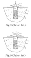
- the entering end “c5" of the body “c2” is first fastened to the spiral tang "b” by adhesives. Then, the bolt “c” and the spiral tang "b” is inserted by force into the round and long hole “e1” of an object “e” until the depth set mark "c4" on the body “c2” is at the same level of the entrance of the round and long hole (as shown in Fig.13 ).
- the body “c2" of the bolt “c” is moved into the spiral tang "b” by turning the head “c1" of the bolt “c” and the spiral tang "b” can be prevented from being rotated by positioning means of the stop tang "b1".
- the spiral tang "b” is expanded and engaged with the inner wall of the round and long hole “e1" (as shown in Fig. 14 ). Therefore, the bolt “c” is reusable since the bolt “c” can be detached when it is not in use any more. In addition, detaching the bolt “c” will facilitate the treatment of the surface of the object "e”.
- the entering end of the body of the bolt is in cone shape and is adhered to the spiral tang.
- the head of the bolt is against the surface of the object and is not spaced from the depth set mark at a distance in advance.
- the bolt will tend to free spin and the body of the bolt will stay within the upper part of the spiral tang and, therefore, cannot be moved downward by turning the head of the bolt. Therefore, it is unable to expand the spiral tang for the purpose of connecting the object.
- an improved reusable expansion anchoring assembly and setting method thereof are disclosed for operators to form an effective connection between the bolt and the spiral tang during normal use, to have the bolt and the spiral tang assembled with each other, and to have the spiral tang expanded radially for connecting an object after the bolt and the spiral tang are both inserted completely into the round and elongated hole of the object even during improper use.
- An object of the present invention is to provide an improved reusable expansion anchoring assembly, where a thread structure is provided at the bottom of the body of a bolt.
- a thread structure is provided at the bottom of the body of a bolt.
- the provided special thread structure at the bottom of the body will lift up the spiral tang and expand to form a strong connection with the object. Consequently, under improper use, when the bolt and the spiral tang are inserted completely into the round and elongated hole of the object, the spiral tang can be moved upward along with threads and expanded, and a strong connection can be formed between the bolt and the object by turning the head of the bolt.
- Another object of the present invention is to provide a setting method of an improved reusable expansion anchoring assembly.
- Another object of the present invention is to provide a setting method of an improved reusable expansion anchoring assembly.
- the present invention provides an improved reusable expansion anchoring assembly, which is received and fixed within a round and elongated hole defined in an object.
- the reusable expansion anchoring assembly comprises a spiral tang and a bolt.
- the spiral tang is formed by spirally coiling a significant long wire around a spindle and has an internal and external diameter with a plurality of gaps. The gaps are spaced equidistantly with each other and parallel to the direction of the spindle.
- a free end is formed at the lower end of the spiral tang while a stop tang is formed at the upper end of the spiral tang.
- the bolt includes a head and a body.
- a spiral part of the body is the coiling part starting from the bottom of the body to form a plurality of threads.
- the threads have equal pitch with one another and are in tapered shape at the bottom of the body.
- the first thread from the bottom of the body enters the spiral tang at upper end so as to be assembled within a gap.
- the largest external diameter of the first thread is larger than the internal diameter of the spiral tang and clear crests and valleys are formed on the tapered-shape threads.
- the spiral tang when the bolt is assembled with the first gap of the spiral tang when inserted into the round and elongated hole, the spiral tang can be adjusted relative to the bolt and can always be expanded and fixed by turning the head of the bolt.
- the largest external diameter of the first thread is larger than the internal diameter of the spiral tang within the range of one-fourth to three-fourths the length of the wire's diameter of spiral tang.
- the valley of the thread 331 is in circular shape, the largest external diameter defined by the crest of the first thread is larger than the smallest internal diameter defined by the valley within the range of one-fourth to three-fourths of the length of the wire's diameter.
- the bolt is made of heat treated medium carbon steel.
- the setting method of the present invention further comprises a step: inserting the spiral tang and the body of the bolt through a thick fixture, where the depth of the round and elongated hole is greater than the difference that results from the total length of the body of the bolt and the spiral tang after assembly minus the thickness of the fixture.
- the partially assembled bolt body and the spiral tang are completely inserted into the round and elongated hole; the head of the bolt is against the surface of an object.
- the spiral tang can be moved upward relative to the bolt, expanded radially, and engaged with the inner wall of the round and elongated hole to perform similar actions of a nut. Thereby, a firm connection between the bolt and the object can be formed.
- the bolt can be removed from the round and elongated hole when turned in counterclockwise direction.
- Fig. 1 shows an exploded view of a preferred embodiment of the reusable expansion anchoring assembly of the present invention.
- Fig. 2 shows a sectional view of the preferred embodiment of the assembled reusable expansion anchoring assembly of the present invention.
- Fig. 3 shows a flowchart of steps for normally inserting a bolt according to the present invention.
- Fig. 4 is a sectional view showing a bolt body and a spiral tang before inserted into a round and elongated hole according to the present invention.
- Fig. 5 is a sectional view showing that a bolt and a spiral tang are inserted into the round and elongated hole, under normal use, and the bolt is not turned according to the present invention.
- Fig. 6 is a sectional view showing that a bolt is turned, under normal use, the spiral tang is in an expanded and fixed condition.
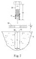
- Fig. 7 is a sectional view showing that a thick fixture is fixed between a bolt head and the surface of an object according to the present invention.
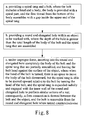
- Fig. 8 shows a flowchart of steps for inserting a bolt under improper use according to the present invention.
- Fig. 9 is a sectional view showing the bolt and the spiral tang where the bolt is completely inserted into the round and elongated hole during improper use according to the present invention.
- Fig. 10 is a sectional view showing that a bolt is turned and the spiral tang is in an expanded and fixed condition when the bolt is completely inserted into the round and elongated hole during improper use according to the present invention.
- Fig. 11 shows an exploded view of a device disclosed by a prior art.
- Fig. 12 shows a sectional view of the assembled device of the prior art.
- Fig. 13 is a sectional view showing the bolt and the spiral tang of the device of the prior art that are inserted into a long round hole, the bolt was not turned under normal use.
- Fig. 14 is a sectional view showing that the bolt is assembled into the spiral tang and the spiral tang is expanded and fixed under normal use according to the prior art.
- Figs. 15 and 16 are sectional views showing that, under improper use, the spiral tang fails to expand by turning the bolt because the bolt is turned but not moved after it is completely inserted into the round and long hole according to the prior art.
- Figs. 17 and 18 are sectional views showing that the spiral tang fails to expand since the spiral tang is compressed at the entering end of the bolt body at the round and long hole according to the prior art.
- a reusable expansion anchoring assembly 1 according to the present invention comprises a spiral tang 2 and a bolt 3.
- the spiral tang 2 is formed by spirally coiling a long wire 21 around a spindle, the long wire has a diameter.
- the lower end of the long wire 21 is a free end and the upper end thereof is designed as a flat stop tang 22.
- the long wire 21 is coiled to form a spiral tang 2; the long wire has a length, an internal diameter d1, an outer diameter d2, and a plurality of gaps "w", where the gaps are separated equidistantly with each other and parallel to the direction of the spindle of the spiral tang 2.
- the stop tang 22 extends from the upper end of the spiral tang 2 toward the direction parallel to the spindle.
- the bolt 3 is made of heat treated medium carbon steel. Further, the bolt 3 can also be made of alloy steel or other metal materials that possess equal or greater strength and hardness than the above heated treated medium carbon steel.
- the bolt 3 includes a head 31 and a long cylinder-shape body 32.
- the head 31 is formed at the upper end of the body 32 and is in hexagonal shape. In practice, the head 31 can be designed in other polygonal shapes or ring shape.
- a spiral part 33 is coiled around the long cylinder-shape body 32 from the bottom thereof toward the head 31 to form a plurality of threads 331, the bottom of the body 32 and part of the body 32 have the threads 331 with equal pitch.
- the bottom of the body 32 is formed with tapered threads and the tapered threads are gradually becoming parallel threads.
- the largest external diameter "D" of the first thread 331 from the bottom of the body 32 is larger than the internal diameter d1 of the spiral tang 2.
- the difference there-between is preferably within the range of one-fourth to three-fourths of the length of the wire's diameter d3.
- the valley of the thread 331 is in circular shape.
- the largest external diameter "D" of the first thread 331 is the outer diameter defined by the crest of the first thread 331, and the internal diameter d1 of the spiral tang 2 is the minimum outer diameter defined by the valley of the first thread 331.
- the difference between the outer diameter defined by the crest and the minimum outer diameter defined by the valley is within the range of one-fourth to three-fourths of the length of the wire's diameter.
- the first thread of the tapered threads has clear crest and valley.
- FIG. 3 shows a preferred embodiment of a setting method of a reusable expansion anchoring assembly of the present invention. This method comprises following steps and is used when proper force is exerted.
- A. Providing a spiral tang 2 and a bolt 3, where the bolt 3 includes a head 31 and a body 32, the body 32 is provided with a spiral part 33, and the first thread 331 from the bottom of the body 32 assembles with a gap "w" inside the upper end of the spiral tang 2;
- step “A” two steps that are provided before the step “A” mentioned above including: a step of forming a depth set mark 34 on the body 32, and a step of processing the bolt 3 made of heat treated medium carbon steel material in order to enhance the strength of the bolt 3 by the heat treatment.
- step “B” the depth "h” of the round and elongated hole 91 is preferably at least 0.5 centimeter longer than the total length h1 of the bolt body 32 and the spiral tang 2 at assembly (as shown in Fig. 4 ).
- step "C” an operator exerts a force to punch the body 32 and the spiral tang 2 that are partially assembled together into the round and elongated hole 91 until the depth set mark 34 is at the entrance of the round and elongated hole (as shown in Fig. 5 ).
- the spiral tang 2 can be inserted and fixed in the round and elongated hole 91 by a resistance from the engagement of the stop tang 22 with the inner wall 92 of the round and elongated hole.
- the spiral tang 2 is expanded radially and engaged with the inner wall 92 of the round and elongated hole of the object 9 to perform similar actions of a nut. Consequently, a firm connection can be formed between the bolt 3 and the object 9 (as shown in Fig. 6 ). Furthermore, when turned counterclockwise, the bolt 3 is also removable from the round and elongated hole 91 of the object 9. In this case, the expanded spiral tang stays and is still engaged with the inner wall 92, the same or another bolt 3 can be inserted again to assemble with the spiral tang.
- head 31 of the bolt 3 when head 31 of the bolt 3 is designed in ring shape, it will be more laborsaving to hang the object 9 by using equipment after connecting the bolt 3 with the object 9, or by increasing the force arm for rotating the bolt 3 after inserting a long rod through the ring.
- a fixture 93 with a thickness h2 (as shown in Fig. 7 ) can be fixed between the head 31 of the bolt 3 and the surface of the object 9.
- the value of the thickness h2 of the fixture 93 should be subtracted from the value of the depth "h" of the round and elongated hole 91.
- the depth of the round and elongated hole 91 should be greater than the difference between the total length "h" of the body 32 of the bolt and the spiral tang 2 minus the thickness h2 of the fixture.
- FIG. 8 another embodiment of the setting method of a reusable expansion anchoring assembly according to the present invention is disclosed, where improper force is used.
- operators fail to obey normal operation procedures and exert force to punch the partially assembled body 32 and the spiral tang 2 completely into the round and elongated hole 91 without noticing the depth set mark 34, and the head 31 of the bolt 3 is against the surface of the object 9 (as shown in Fig. 9 ). Because the depth "h" of the round and elongated hole 91 is enough for receiving the partially assembled body 32 and the spiral tang 2, the spiral tang 2 will not be compressed completely to the bottom of the round and elongated hole 91.
- a force "F" can be formed to move the spiral tang 2 upward by the first thread 331 provided with clear crest and valley.
- the spiral tang can be moved upward and expanded relative to the body 32 of the bolt 3.
- the spiral tang 2 is expanded radially and engaged with the inner wall 92 of the round and elongated hole 91 of the object 9, consequently, a firm connection between the bolt 3 and the object 9 can be formed.
- the bolt 3 is removable from the round and elongated hole 91 of the object 9 when turned counterclockwise.
- the present invention has the following advantages:
- the bolt can be assembled with the spiral tang to form a firm connection between the bolt and the object.
- the strength of the bolt can be strengthened to prevent the bolt from breaking as a result of the strength deficiency, and, consequently, the setting quality can be ensured.
- the depth of the round and elongated hole is prolonged in order to prevent the threads from not being able to assemble the bolt and the spiral tang after the spiral tang is compressed and destroyed at the bottom of the round and long hole.
- the present invention can provide a reusable expansion anchoring assembly and setting method thereof, where the bolt can be effectively connected with the spiral tang, and the connection can be maintained when the bolt and the spiral tang are inserted completely into the round and elongated hole of the object. It is new and can be put into industrial use.
Landscapes
- Engineering & Computer Science (AREA)
- General Engineering & Computer Science (AREA)
- Mechanical Engineering (AREA)
- Dowels (AREA)
Priority Applications (1)
| Application Number | Priority Date | Filing Date | Title |
|---|---|---|---|
| EP09000770A EP2208897A1 (fr) | 2009-01-20 | 2009-01-20 | Ensemble de cheville à expansion amélioré et réutilisable et son procédé de fixage |
Applications Claiming Priority (1)
| Application Number | Priority Date | Filing Date | Title |
|---|---|---|---|
| EP09000770A EP2208897A1 (fr) | 2009-01-20 | 2009-01-20 | Ensemble de cheville à expansion amélioré et réutilisable et son procédé de fixage |
Publications (1)
| Publication Number | Publication Date |
|---|---|
| EP2208897A1 true EP2208897A1 (fr) | 2010-07-21 |
Family
ID=40823090
Family Applications (1)
| Application Number | Title | Priority Date | Filing Date |
|---|---|---|---|
| EP09000770A Withdrawn EP2208897A1 (fr) | 2009-01-20 | 2009-01-20 | Ensemble de cheville à expansion amélioré et réutilisable et son procédé de fixage |
Country Status (1)
| Country | Link |
|---|---|
| EP (1) | EP2208897A1 (fr) |
Cited By (3)
| Publication number | Priority date | Publication date | Assignee | Title |
|---|---|---|---|---|
| CZ304376B6 (cs) * | 2012-12-18 | 2014-04-02 | ÄŚVUT v Praze, Fakulta strojnĂ | Vinutá matice |
| CZ304377B6 (cs) * | 2012-12-18 | 2014-04-02 | ÄŚVUT v Praze, Fakulta strojnĂ | Vinutý šroub |
| CN113613844A (zh) * | 2019-06-04 | 2021-11-05 | 株式会社三友精机 | 尾柄折断去除工具及尾柄折断去除方法 |
Citations (3)
| Publication number | Priority date | Publication date | Assignee | Title |
|---|---|---|---|---|
| BE536820A (fr) * | ||||
| AU570000B2 (en) * | 1982-06-01 | 1988-03-03 | Fastening Supplies Pty. Ltd. | Dowel with expansible helical spring |
| US5006023A (en) | 1990-04-24 | 1991-04-09 | Stanley Kaplan | Strip-out preventing anchoring assembly and method of anchoring |
-
2009
- 2009-01-20 EP EP09000770A patent/EP2208897A1/fr not_active Withdrawn
Patent Citations (3)
| Publication number | Priority date | Publication date | Assignee | Title |
|---|---|---|---|---|
| BE536820A (fr) * | ||||
| AU570000B2 (en) * | 1982-06-01 | 1988-03-03 | Fastening Supplies Pty. Ltd. | Dowel with expansible helical spring |
| US5006023A (en) | 1990-04-24 | 1991-04-09 | Stanley Kaplan | Strip-out preventing anchoring assembly and method of anchoring |
Cited By (3)
| Publication number | Priority date | Publication date | Assignee | Title |
|---|---|---|---|---|
| CZ304376B6 (cs) * | 2012-12-18 | 2014-04-02 | ÄŚVUT v Praze, Fakulta strojnĂ | Vinutá matice |
| CZ304377B6 (cs) * | 2012-12-18 | 2014-04-02 | ÄŚVUT v Praze, Fakulta strojnĂ | Vinutý šroub |
| CN113613844A (zh) * | 2019-06-04 | 2021-11-05 | 株式会社三友精机 | 尾柄折断去除工具及尾柄折断去除方法 |
Similar Documents
| Publication | Publication Date | Title |
|---|---|---|
| AU719616B2 (en) | Self-drilling/self-tapping fastener | |
| US8567028B2 (en) | Injector sleeve removal device and method of use | |
| US3875649A (en) | Coldworking method and apparatus with frangible head flange | |
| US20080193256A1 (en) | Spin resistant threaded insert | |
| TWI622711B (zh) | 在中間螺紋區段上具有不連續性的螺釘及其生產方法與應用 | |
| CN101542181A (zh) | 用于盲孔安装的密封塞 | |
| DE102010016797A1 (de) | Spreizanker | |
| JP6272513B2 (ja) | 拡張式アンカー | |
| US4259890A (en) | Removable anchor assemblies | |
| JP5619748B2 (ja) | 締結装置 | |
| EP3399200B1 (fr) | Vis pour feuilles de fer minces | |
| EP2522862A1 (fr) | Ensemble de fixation | |
| EP2208897A1 (fr) | Ensemble de cheville à expansion amélioré et réutilisable et son procédé de fixage | |
| US9551157B2 (en) | Unit fixing insulation to a wall | |
| US12420341B2 (en) | Blind fastener | |
| US20100180541A1 (en) | Reusable Expansion Anchoring Assembly and Setting Method Thereof | |
| US20110206480A1 (en) | Device for blind fixation | |
| JP2006097893A (ja) | ねじ山形成ねじを採用した固定装置 | |
| JP6228203B2 (ja) | ねじ部品及びねじ部品の製造方法 | |
| EP0560789A1 (fr) | Procede de fixation ameliore. | |
| CN107842545A (zh) | 一种单面铆接螺栓及其铆接方法 | |
| WO2007127300A1 (fr) | Ensemble rivet de taraudage et d'auto-polissage | |
| CN101793277A (zh) | 可重复使用的膨胀螺丝的改良装置及其安装方法 | |
| TW201028556A (en) | Improved reusable expansion anchoring assembly and setting method thereof | |
| CN212959695U (zh) | 一种用于钢丝绳绳头自动锁紧的连接装置 |
Legal Events
| Date | Code | Title | Description |
|---|---|---|---|
| PUAI | Public reference made under article 153(3) epc to a published international application that has entered the european phase |
Free format text: ORIGINAL CODE: 0009012 |
|
| AK | Designated contracting states |
Kind code of ref document: A1 Designated state(s): AT BE BG CH CY CZ DE DK EE ES FI FR GB GR HR HU IE IS IT LI LT LU LV MC MK MT NL NO PL PT RO SE SI SK TR |
|
| AX | Request for extension of the european patent |
Extension state: AL BA RS |
|
| AKY | No designation fees paid | ||
| STAA | Information on the status of an ep patent application or granted ep patent |
Free format text: STATUS: THE APPLICATION IS DEEMED TO BE WITHDRAWN |
|
| 18D | Application deemed to be withdrawn |
Effective date: 20110122 |