EP2211014A2 - High control accuracy automatic device for controlling a walkway entrance - Google Patents
High control accuracy automatic device for controlling a walkway entrance Download PDFInfo
- Publication number
- EP2211014A2 EP2211014A2 EP10151341A EP10151341A EP2211014A2 EP 2211014 A2 EP2211014 A2 EP 2211014A2 EP 10151341 A EP10151341 A EP 10151341A EP 10151341 A EP10151341 A EP 10151341A EP 2211014 A2 EP2211014 A2 EP 2211014A2
- Authority
- EP
- European Patent Office
- Prior art keywords
- controlling
- wing
- walkway
- entrance
- walkway entrance
- Prior art date
- Legal status (The legal status is an assumption and is not a legal conclusion. Google has not performed a legal analysis and makes no representation as to the accuracy of the status listed.)
- Withdrawn
Links
- 238000010168 coupling process Methods 0.000 claims description 17
- 238000005859 coupling reaction Methods 0.000 claims description 17
- 230000008878 coupling Effects 0.000 claims description 16
- 230000004913 activation Effects 0.000 claims description 5
- 238000000926 separation method Methods 0.000 claims description 4
- 230000000694 effects Effects 0.000 claims description 2
- 230000009471 action Effects 0.000 description 7
- 230000000295 complement effect Effects 0.000 description 3
- 238000009434 installation Methods 0.000 description 2
- 230000004888 barrier function Effects 0.000 description 1
- 230000000903 blocking effect Effects 0.000 description 1
- 230000001419 dependent effect Effects 0.000 description 1
- 238000001514 detection method Methods 0.000 description 1
- 238000003780 insertion Methods 0.000 description 1
- 230000037431 insertion Effects 0.000 description 1
- 230000002452 interceptive effect Effects 0.000 description 1
- 238000012986 modification Methods 0.000 description 1
- 230000004048 modification Effects 0.000 description 1
- 230000010363 phase shift Effects 0.000 description 1
- 230000011664 signaling Effects 0.000 description 1
Images

Classifications
-
- E—FIXED CONSTRUCTIONS
- E06—DOORS, WINDOWS, SHUTTERS, OR ROLLER BLINDS IN GENERAL; LADDERS
- E06B—FIXED OR MOVABLE CLOSURES FOR OPENINGS IN BUILDINGS, VEHICLES, FENCES OR LIKE ENCLOSURES IN GENERAL, e.g. DOORS, WINDOWS, BLINDS, GATES
- E06B11/00—Means for allowing passage through fences, barriers or the like, e.g. stiles
- E06B11/08—Turnstiles; Gates for control of entry or exit of persons, e.g. in supermarkets
Definitions
- the present invention refers to a high control accuracy automatic device for controlling a walkway entrance.
- the purpose of such devices is that of allowing one passage direction, blocking the movement in the opposite direction. They may be set both in the normally closed configuration and in the normally open configuration.
- Such devices usually comprise a support upright constrained on which is a cantilever wing free to rotate around the upright.
- the wing may rotate between a closure position wherein it is positioned transverse to the allowed walkway passage direction, and an opening position wherein it is positioned parallel to the allowed direction.
- the movement of the wing is controlled through special means comprising an actuator and a stop system possibly controlled by a control logic.
- the actuator may be activated manually from a remote or non-remote position, or automatically wherein actuation occurs through the control logic, which receives - in input - an actuation signal generated by a detector signalling the presence of an approaching pedestrian.
- the travel of the wing is controlled both to close and open by means of a sensor capable of detecting the instantaneous position of the wing.
- the control logic may thus detect when the wing reaches the preset closed or open position, and deliver a corresponding signal to the means for moving the wing.
- the stop system is also activated even in case of collision against an obstacle during the step of moving towards the closed or open position, or in case of a forced entry attempt such as for example access in the direction opposite to the allowed passage direction.
- the known devices for controlling a walkway entrance are not capable of guaranteeing a high positioning accuracy at the preset positions.
- prior art devices are not capable of offering a two-directional opening. Therefore, this implies that a specially made model is required depending on whether the device should open through a clockwise or anticlockwise rotation.
- the prior art stop system of the devices for controlling a walkway entrance is not capable of offering a suitable braking action.
- An object of the present invention is that of overcoming the abovementioned drawbacks and in particular that of providing a device for controlling a walkway entrance, such device being capable of guaranteeing high positioning accuracy at the preset open and closed positions.
- Another object of the present invention is that of providing a device for controlling a walkway entrance, such device being easy and quick to install.
- Further object of the present invention is that of providing a device for controlling a walkway entrance of the two-directional type.
- Last but not least object of the present invention is that of providing a device for controlling a walkway entrance, such device being capable of offering a suitable braking action in case of actuation of the safety system.
- a device for controlling a walkway entrance is shown indicated in its entirety with 10.
- the device for controlling a walkway entrance 10 comprises at least one support upright 11 constrained onto which is a cantilever wing 12 free to rotate around the upright 11 between a closed position wherein it is positioned transverse with respect to the allowed walkway passage direction, and an open position wherein it ends up positioned parallel to such allowed direction.
- means 13-17 for moving the wing 12 Accommodated inside the upright 11 are means 13-17 for moving the wing 12, such means comprising processing means 14 which control the activation of an actuator 13 and a braking group 15.
- Both the actuator 13, and the braking group 15 operate on a support rod 19 to which the wing 12 is constrained and it serves as a rotational pin of the same.
- the braking group 15 is interposed between the actuator 13 and the rod 19.
- the processing means 14 receive - in input - an activation signal which, depending on the model, may be entered manually, for example through a switch, or generated by a presence detector 17 upon detection of a pedestrian approaching in the allowed passage direction or in the opposite direction.
- the presence detector 17 respectively generates an opening or closing signal.
- the presence detector 17 may be obtained by means of a microwave radar or photocell.
- the processing means 14 In order to control the travel of the wing 12, the processing means 14 also receive - in input - a signal generated by a positioning sensor 16 which detects the instantaneous position of the wing 12.
- the positioning sensor 16 is a magnetic sensor capable of guaranteeing a particularly high degree of accuracy and in particular less than one rotation degree.
- the magnetic positioning sensor 16 comprises a permanent magnet 18, preferably extending axially, accommodated in a seat 20 integral to the rotational pin 19 of the wing 12 where the seat 20 is arranged transverse to the axis of the rotational pin 19.
- the permanent magnet 18 may be disc-, ring-, square- or cylindrical-shaped.
- an electronic sensor 21 Arranged at the upper part of the permanent magnet 18 is an electronic sensor 21 capable of calculating the angle which, depending on the instantaneous arrangement of the permanent magnet 18, is formed between the North-South axis of such magnet 18 and a preset fixed axis.
- the detected angle forms the base for the processing means 14 for controlling the stop accuracy of the wing 12 at the desired position.
- the permanent magnet 18 may be arranged in such a manner that its North-South axis coincides with the main extension direction of the wing 12 and the fixed axis be set corresponding to a closed position of the wing 12 perpendicular to the allowed direction of movement.
- the exact open position shall be attained when the electronic sensor 21 detects an angle equivalent to 90°.
- the permanent magnet 18 is positioned in axis with the electronic sensor 21 and, at such position, the absolute position of the wing 12 is calculated.
- Calibration also referred to as resetting, is required during installation to define the parameters required for proper operation: in fact, the operational range, which may also be freely set by the end user, is set.
- Typical operational ranges allow the wing to rotate by 90°, 120°, 180° or 360°.
- the travel angle of the wing 12 may however be set at will depending on the needs.
- the electronic sensor 21 delivers two sinusoidal waveforms having a period of 180° and having a 45° phase shift with respect to each other.
- the absolute position is identified in a 180° range.
- the processing means 14 stop the actuator 13 and activate the braking group 15.
- the braking group 15 is particularly small in size due to the use of a pair of magnetic brakes arranged in such a manner to be able to operate together summing up their effects.
- a brake support 25 made up of a cylindrical shaft 26 coupled to which is a pair of discoidal-shaped anchor elements 24.
- the anchor elements 24 are coupled to the cylindrical shaft 26 in such a manner to be able to move axially along the same 26, but not be able to rotate with respect to the same 26.
- the cylindrical shaft 26 is provided with a coupling interface 23 integral to the same 26 and disc-shaped and, regarding the pair of anchor elements 24, an upper anchor element 24' is coupled at the upper part and a lower anchor element 24" is coupled at the lower part with respect to such coupling interface 23.
- Such coupling interface 23 is preferably arranged at an intermediate position with respect to the axial extension of the shaft 26.
- the cylindrical shaft 26 of the brake support 25 is firmly fixed to the shaft of the actuator 13 at one end and to the rod 19 for supporting the wing 12 at the other end, with the aim of transmitting the rotational movement imparted by the actuator 13 to the rod 19 of the wing 12.
- the coupling interface 23 comprises a plurality of elements 27 projecting towards the axial direction, in the illustrated embodiment such means being made up of screw heads 27 screwed in dedicated first seats 28 made in the coupling interface 23.
- the projecting elements 27 may be made in a single piece with the coupling interface 23.
- anchor elements 24 are provided with second seats 29 complementary to the projecting elements 27 of the coupling interface 23.
- the anchor elements 24 are thus drawn in the rotational movement imparted to the shaft 26 due to the coupling between the projecting elements 27 and the second seats 29 though free to perform minimum translation movements along the axis of the shaft 26.
- the cylindrical shaft 26 has a polygonal section, preferably hexagonal, and the anchor elements 24 have a complementary central seat in which the cylindrical shaft 26 is free to slide.
- annular discoidal-shaped separation interface 23' interposed between the anchor elements 24 and coupled to the cylindrical shaft 26 through insertion into the central seat thereof.
- such separation interface 23' is made of a material capable of absorbing impact - in the sense of reducing the noise caused by the same - generated by the collision of the two anchor elements 24 due to the vertical fall of the upper anchor element 24' onto the lower anchor element 24" at the end of the braking action exerted on the same 24',24".
- the disc-shaped interface 23 is made of PVC material.
- the magnetic devices 22 are activated by the processing means 14 when the system detects a situation that requires the intervention of the braking group 15. When actuated, the magnetic devices 22 attract, by translating along the cylindrical shaft 26, the anchor elements 24 thereto interfering with the rotational movement of the same in order to exert a braking action.
- the braking action is transmitted to the shaft 26 through the coupling between the projecting elements 27 and the second seats 29 and thus also to the support rod 19 of the wing 12.
- the braking action is transmitted to the shaft 26 through the shape-coupling between the shaft 26 and the central seat of the anchor elements 24 which, being complementary polygonal, do not allow a relative rotation between the elements 26,24.
- the travel of the wing 12 is controlled both when closing and opening by means of a positioning sensor 16 capable of determining when the wing 12 has reached the preset closed or open position and providing to the movement means of the wing a corresponding stop signal.
- the movement means of the devices for controlling a walkway entrance are provided with a stop system, activated both in case of collision with an obstacle during the step of moving towards the closed or open position and in case of an attempt of forced entry such as for example access in the direction opposite to the allowed passage direction.
- the device for controlling a walkway entrance guarantees high positioning accuracy at the preset open and closed positions.
- the initial installation is particularly facilitated in that the open and closed position can be defined in a quick and accurate manner.
- the device for controlling a walkway entrance is capable of offering suitable braking action in case of activation of the safety system.
Landscapes
- Engineering & Computer Science (AREA)
- Civil Engineering (AREA)
- Structural Engineering (AREA)
- Control Of Position, Course, Altitude, Or Attitude Of Moving Bodies (AREA)
- Escalators And Moving Walkways (AREA)
Abstract
The present invention refers to a high control accuracy automatic device for controlling a walkway entrance, which comprises at least one support upright (11) constrained on which is at least one cantilever wing (12) free to rotate around the upright (11) between a closed position, in which it is arranged in a manner transverse to an allowed passage direction, and an open position, in which it is arranged in a manner parallel to the allowed passage direction, accommodated inside the upright being means (13-17) for moving the wing (12) comprising at least one positioning sensor (16) intended to detect an instantaneous position of the wing (12), and it is characterized in that the positioning sensor (16) is a magnetic sensor.
Preferably, the magnetic sensor (16) comprises a permanent magnet (18) having a North-South axis transverse to the support upright (11), the permanent magnet (18) being associated to an electronic sensor (21) capable of calculating the angle that is generated between the North-South axis and a preset fixed axis.
Preferably, the magnetic sensor (16) comprises a permanent magnet (18) having a North-South axis transverse to the support upright (11), the permanent magnet (18) being associated to an electronic sensor (21) capable of calculating the angle that is generated between the North-South axis and a preset fixed axis.
Description
- The present invention refers to a high control accuracy automatic device for controlling a walkway entrance.
- Currently used for controlling the walkway entrance in certain facilities, such as for example offices, shops or entrance platform for public transport means, are special devices, such as for example barriers or automatically opening doors.
- In the most common applications, the purpose of such devices is that of allowing one passage direction, blocking the movement in the opposite direction. They may be set both in the normally closed configuration and in the normally open configuration.
- Such devices usually comprise a support upright constrained on which is a cantilever wing free to rotate around the upright.
- In particular, the wing may rotate between a closure position wherein it is positioned transverse to the allowed walkway passage direction, and an opening position wherein it is positioned parallel to the allowed direction.
- Usually, the movement of the wing is controlled through special means comprising an actuator and a stop system possibly controlled by a control logic. The actuator may be activated manually from a remote or non-remote position, or automatically wherein actuation occurs through the control logic, which receives - in input - an actuation signal generated by a detector signalling the presence of an approaching pedestrian.
- The travel of the wing is controlled both to close and open by means of a sensor capable of detecting the instantaneous position of the wing. The control logic may thus detect when the wing reaches the preset closed or open position, and deliver a corresponding signal to the means for moving the wing.
- Furthermore, in order to guarantee suitable safety of use, the stop system is also activated even in case of collision against an obstacle during the step of moving towards the closed or open position, or in case of a forced entry attempt such as for example access in the direction opposite to the allowed passage direction.
- Currently known devices for controlling a walkway entrance are not without drawbacks.
- In particular, the implementation of such devices is particularly difficult given that it is quite complicated to accurately preset the open and closed positions.
- Furthermore, even in case of an accurate presetting, the known devices for controlling a walkway entrance are not capable of guaranteeing a high positioning accuracy at the preset positions.
- Additionally, prior art devices are not capable of offering a two-directional opening. Therefore, this implies that a specially made model is required depending on whether the device should open through a clockwise or anticlockwise rotation.
- In addition, the prior art stop system of the devices for controlling a walkway entrance is not capable of offering a suitable braking action.
- An object of the present invention is that of overcoming the abovementioned drawbacks and in particular that of providing a device for controlling a walkway entrance, such device being capable of guaranteeing high positioning accuracy at the preset open and closed positions.
- Another object of the present invention is that of providing a device for controlling a walkway entrance, such device being easy and quick to install.
- Further object of the present invention is that of providing a device for controlling a walkway entrance of the two-directional type.
- Last but not least object of the present invention is that of providing a device for controlling a walkway entrance, such device being capable of offering a suitable braking action in case of actuation of the safety system.
- These and other objects according to the present invention are attained by providing a device for controlling a walkway entrance as outlined in claim 1.
- Further characteristics of the device for controlling a walkway entrance are subject of the dependent claims.
- Characteristics and advantages of a device for controlling a walkway entrance according to the present invention shall be clearer from the exemplifying and non-limiting description that follows referring to the attached schematic drawings, wherein:
-
figure 1 is a side elevational view of a device for controlling a walkway entrance according to the present invention; -
figures 2a-2c are respectively a side elevational view, front elevational view, and sectional view along line A-A, of the elements forming the means for moving and controlling the wing of the device for controlling a walkway entrance according to the present invention; -
figure 3 is a perspective view of means for positioning the device for controlling a walkway entrance according to the present invention; -
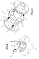
figure 4a is a perspective view of a detail of a first embodiment of the braking group used in the device for controlling a walkway entrance according to the present invention; -
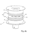
figure 4b is a perspective view of a second embodiment of the braking group used in the device for controlling a walkway entrance according to the present invention. - Referring to the figures, a device for controlling a walkway entrance is shown indicated in its entirety with 10.
- The device for controlling a
walkway entrance 10 comprises at least one support upright 11 constrained onto which is acantilever wing 12 free to rotate around the upright 11 between a closed position wherein it is positioned transverse with respect to the allowed walkway passage direction, and an open position wherein it ends up positioned parallel to such allowed direction. - Accommodated inside the upright 11 are means 13-17 for moving the
wing 12, such means comprising processing means 14 which control the activation of anactuator 13 and abraking group 15. Both theactuator 13, and thebraking group 15 operate on asupport rod 19 to which thewing 12 is constrained and it serves as a rotational pin of the same. In particular, thebraking group 15 is interposed between theactuator 13 and therod 19. - The processing means 14 receive - in input - an activation signal which, depending on the model, may be entered manually, for example through a switch, or generated by a
presence detector 17 upon detection of a pedestrian approaching in the allowed passage direction or in the opposite direction. - Correspondingly, the
presence detector 17 respectively generates an opening or closing signal. - Preferably, the
presence detector 17 may be obtained by means of a microwave radar or photocell. - In order to control the travel of the
wing 12, the processing means 14 also receive - in input - a signal generated by apositioning sensor 16 which detects the instantaneous position of thewing 12. - According to the present invention the
positioning sensor 16 is a magnetic sensor capable of guaranteeing a particularly high degree of accuracy and in particular less than one rotation degree. - In the illustrated preferred embodiment, the
magnetic positioning sensor 16 comprises apermanent magnet 18, preferably extending axially, accommodated in aseat 20 integral to therotational pin 19 of thewing 12 where theseat 20 is arranged transverse to the axis of therotational pin 19. - Depending on the model of the automatic device for controlling access, the
permanent magnet 18 may be disc-, ring-, square- or cylindrical-shaped. - Arranged at the upper part of the
permanent magnet 18 is anelectronic sensor 21 capable of calculating the angle which, depending on the instantaneous arrangement of thepermanent magnet 18, is formed between the North-South axis ofsuch magnet 18 and a preset fixed axis. - The detected angle forms the base for the processing means 14 for controlling the stop accuracy of the
wing 12 at the desired position. - For example, the
permanent magnet 18 may be arranged in such a manner that its North-South axis coincides with the main extension direction of thewing 12 and the fixed axis be set corresponding to a closed position of thewing 12 perpendicular to the allowed direction of movement. - In such a case, the exact open position shall be attained when the
electronic sensor 21 detects an angle equivalent to 90°. - Regarding the initial setting, the
permanent magnet 18 is positioned in axis with theelectronic sensor 21 and, at such position, the absolute position of thewing 12 is calculated. - Calibration, also referred to as resetting, is required during installation to define the parameters required for proper operation: in fact, the operational range, which may also be freely set by the end user, is set.
- Typical operational ranges allow the wing to rotate by 90°, 120°, 180° or 360°. The travel angle of the
wing 12 may however be set at will depending on the needs. - It is possible to establish the absolute position due to the fact that the
electronic sensor 21 delivers two sinusoidal waveforms having a period of 180° and having a 45° phase shift with respect to each other. By calculating the tangent arc of the division between the two angles the absolute position is identified in a 180° range. - During the travel thereof, should the
wing 12 encounter obstacles or in case of an attempt to force the device to allow passage towards the direction opposite to the allowed one, the processing means 14 stop theactuator 13 and activate thebraking group 15. - In the illustrated advantageous embodiment, the
braking group 15 is particularly small in size due to the use of a pair of magnetic brakes arranged in such a manner to be able to operate together summing up their effects. - Such result is attained by using a
brake support 25 made up of acylindrical shaft 26 coupled to which is a pair of discoidal-shaped anchor elements 24. Theanchor elements 24 are coupled to thecylindrical shaft 26 in such a manner to be able to move axially along the same 26, but not be able to rotate with respect to the same 26. - In a first preferred embodiment of the
brake support 25, thecylindrical shaft 26 is provided with acoupling interface 23 integral to the same 26 and disc-shaped and, regarding the pair ofanchor elements 24, an upper anchor element 24' is coupled at the upper part and alower anchor element 24" is coupled at the lower part with respect tosuch coupling interface 23. -
Such coupling interface 23 is preferably arranged at an intermediate position with respect to the axial extension of theshaft 26. - The
cylindrical shaft 26 of thebrake support 25 is firmly fixed to the shaft of theactuator 13 at one end and to therod 19 for supporting thewing 12 at the other end, with the aim of transmitting the rotational movement imparted by theactuator 13 to therod 19 of thewing 12. - The
coupling interface 23 comprises a plurality ofelements 27 projecting towards the axial direction, in the illustrated embodiment such means being made up ofscrew heads 27 screwed in dedicatedfirst seats 28 made in thecoupling interface 23. - In an entirely analogous manner, the projecting
elements 27 may be made in a single piece with thecoupling interface 23. - In order to prevent the relative rotation between the two
anchor elements 24 and theshaft 26,such anchor elements 24 are provided withsecond seats 29 complementary to the projectingelements 27 of thecoupling interface 23. - The
anchor elements 24 are thus drawn in the rotational movement imparted to theshaft 26 due to the coupling between the projectingelements 27 and thesecond seats 29 though free to perform minimum translation movements along the axis of theshaft 26. - In a second preferred embodiment of the
brake support 25, thecylindrical shaft 26 has a polygonal section, preferably hexagonal, and theanchor elements 24 have a complementary central seat in which thecylindrical shaft 26 is free to slide. - Thus obtained is a coupling between the
cylindrical shaft 26 and theanchor elements 24 such that the latter may translate axially along theshaft 26, but they are drawn in the rotational movement imparted to theshaft 26. - Preferably, provided for is an annular discoidal-shaped separation interface 23' interposed between the
anchor elements 24 and coupled to thecylindrical shaft 26 through insertion into the central seat thereof. - Preferably, such separation interface 23' is made of a material capable of absorbing impact - in the sense of reducing the noise caused by the same - generated by the collision of the two
anchor elements 24 due to the vertical fall of the upper anchor element 24' onto thelower anchor element 24" at the end of the braking action exerted on the same 24',24". For example, the disc-shapedinterface 23 is made of PVC material. Provided for are twomagnetic devices 22, which are opposite to the upper 24' and lower 24"anchor elements 24, - respectively at the upper part and lower part - such devices being disc-shaped and fixedly constrained to thesupport upright 11 of the device for controlling awalkway entrance 10. - The
magnetic devices 22 are activated by the processing means 14 when the system detects a situation that requires the intervention of thebraking group 15. When actuated, themagnetic devices 22 attract, by translating along thecylindrical shaft 26, theanchor elements 24 thereto interfering with the rotational movement of the same in order to exert a braking action. - According to the first preferred embodiment of the
brake support 25, the braking action is transmitted to theshaft 26 through the coupling between the projectingelements 27 and thesecond seats 29 and thus also to thesupport rod 19 of thewing 12. - According to the second preferred embodiment of the
brake support 25, the braking action is transmitted to theshaft 26 through the shape-coupling between theshaft 26 and the central seat of theanchor elements 24 which, being complementary polygonal, do not allow a relative rotation between theelements - The travel of the
wing 12 is controlled both when closing and opening by means of apositioning sensor 16 capable of determining when thewing 12 has reached the preset closed or open position and providing to the movement means of the wing a corresponding stop signal. - Furthermore, in order to guarantee suitable safety of use, the movement means of the devices for controlling a walkway entrance are provided with a stop system, activated both in case of collision with an obstacle during the step of moving towards the closed or open position and in case of an attempt of forced entry such as for example access in the direction opposite to the allowed passage direction.
- Characteristics and advantages of the device subject of the invention are clear from the description outlined above.
- Due to the use of the particular magnetic sensor, the device for controlling a walkway entrance guarantees high positioning accuracy at the preset open and closed positions.
- Furthermore, the initial installation is particularly facilitated in that the open and closed position can be defined in a quick and accurate manner.
- Last but not least, the device for controlling a walkway entrance is capable of offering suitable braking action in case of activation of the safety system.
- Lastly, it is clear that the device thus conceived is susceptible to various modifications and variants, all falling within the invention; furthermore, all details may be replaced by technically equivalent elements. In practice, all materials used, as well as the dimensions, may vary depending on the technical requirements.
Claims (14)
- Device for controlling a walkway entrance (10) comprising at least one support upright (11) constrained on which is at least one cantilever wing (12) free to rotate around said upright (11) between a closed position, in which it is arranged in a manner transverse to an allowed passage direction, and an open position, in which it is arranged in a manner parallel to said passage direction, accommodated inside said upright being means (13-17) for moving said wing (12) comprising at least one positioning sensor (16) intended to detect an instantaneous position of said wing (12), characterised in that said positioning sensor (16) is a magnetic sensor.
- Device for controlling a walkway entrance (10) according to claim 1 characterised in that said magnetic sensor (16) comprises a permanent magnet (18) having a North-South axis transverse to said support upright (11), said permanent magnet (18) being associated to an electronic sensor (21) capable of calculating the angle that is generated between said North-South axis and a preset fixed axis.
- Device for controlling a walkway entrance (10) according to claim 1 or 2 characterised in that said movement means (13-17) comprise processing means (14) adapted to control the activation of an actuator (13) and a braking group (15), said actuator (13) and said braking group (15) operating on support rod (19) to which said wing (12) is constrained, said support rod (19) serving as a rotational pin for said wing (12).
- Device for controlling a walkway entrance (10) according to claim 3 characterised in that said movement means (13-17) comprise a presence detector (17) adapted to generate a signal to activate said actuator (13) and/or said braking group (15).
- Device for controlling a walkway entrance (10) according to one of claims 3 or 4 characterised in that said braking group (15) is made up of a pair of magnetic brakes arranged facing each other in such a manner to sum up their effects.
- Device for controlling a walkway entrance (10) according to claim 5 characterised in that said braking group (15) comprises two annular discoidal-shaped magnetic devices (22) accommodated on a brake support (25) comprising a cylindrical shaft (26) and a pair of annular discoidal-shaped anchor elements (24), said pair of anchor elements (24) being coupled to said cylindrical shaft (26) with a free-in-translation and integral-in-rotation coupling, said two magnetic devices (22) being arranged facing - respectively at the upper and lower part - an upper anchor element (24') and a lower anchor element (24") of said pair of anchor elements (24).
- Device for controlling a walkway entrance (10) according to claim 6 characterised in that said cylindrical shaft (26) is provided with a coupling interface (23) integral to the same (26), said coupling interface (23) being shaped to form a disc and arranged in a manner transverse to said shaft (26), said upper anchor element (24') and said lower anchor element (24") of said pair of anchor elements (24) being coupled - respectively at the upper part and lower part- to said coupling interface (23), said coupling interface (23) comprising a plurality of projecting elements (27) adapted to cooperate with respective second seats (29) present on said anchor elements (24).
- Device for controlling a walkway entrance (10) according to claim 7 characterised in that said projecting elements (27) are made up of screw heads screwed in dedicated first seats (28) obtained in said coupling interface (23).
- Device for controlling a walkway entrance (10) according to claim 6 characterised in that said cylindrical shaft (26) has a polygonal section and said anchor elements (24) have a central seat shaped complementarily to said polygonal section, said cylindrical shaft (26) being free to slide in said central seat.
- Device for controlling a walkway entrance (10) according to claim 9 characterised in that it comprises an annular discoidal-shaped separation interface (23') interposed between said anchor elements (24) and coupled to said cylindrical shaft (26), said discoidal-shaped separation interface (23') being made of a material capable of absorbing impact.
- Device for controlling a walkway entrance (10) according to any one of claims 9 to 10 characterised in that said cylindrical shaft (26) has a hexagonal section.
- Device for controlling a walkway entrance (10) according to any one of claims 6 to 11 characterised in that said magnetic devices (22) are activated by said electronic means (14) in case of an activation signal of said braking group (15).
- Device for controlling a walkway entrance (10) according to one of claims 6 to 12 characterised in that said cylindrical shaft (26) is firmly fixed at one end to a drive shaft of said actuator (13) and at the other end to said support rod (19) of said wing (12).
- Device for controlling a walkway entrance (10) according to one of claims 6 to 13 characterised in that said two magnetic devices (22) are constrained fixedly to said support upright (11).
Applications Claiming Priority (1)
| Application Number | Priority Date | Filing Date | Title |
|---|---|---|---|
| IT000055A ITMI20090055A1 (en) | 2009-01-21 | 2009-01-21 | AUTOMATIC PEDESTRIAN ACCESS CONTROL DEVICE WITH HIGH PRECISION CONTROL |
Publications (1)
| Publication Number | Publication Date |
|---|---|
| EP2211014A2 true EP2211014A2 (en) | 2010-07-28 |
Family
ID=41090215
Family Applications (1)
| Application Number | Title | Priority Date | Filing Date |
|---|---|---|---|
| EP10151341A Withdrawn EP2211014A2 (en) | 2009-01-21 | 2010-01-21 | High control accuracy automatic device for controlling a walkway entrance |
Country Status (2)
| Country | Link |
|---|---|
| EP (1) | EP2211014A2 (en) |
| IT (1) | ITMI20090055A1 (en) |
Cited By (3)
| Publication number | Priority date | Publication date | Assignee | Title |
|---|---|---|---|---|
| WO2014169886A1 (en) * | 2013-04-17 | 2014-10-23 | Cominfo A.S. | Equipment for access control |
| RU168073U1 (en) * | 2016-08-05 | 2017-01-17 | Общество с ограниченной ответственностью ООО "ВОЗРОЖДЕНИЕ" | GATE |
| ITUB20153132A1 (en) * | 2015-08-14 | 2017-02-14 | Zwei S R L | Passage barrier system |
Family Cites Families (3)
| Publication number | Priority date | Publication date | Assignee | Title |
|---|---|---|---|---|
| EP0190228A1 (en) * | 1984-07-30 | 1986-08-13 | CARROLL, Noel | Gate systems |
| DE9315542U1 (en) * | 1993-10-07 | 1994-07-14 | Wanzl Metallwarenfabrik Gmbh, 89340 Leipheim | Round column-shaped swing door for one person passage |
| DE102006030724B4 (en) * | 2006-06-30 | 2017-06-08 | Wanzl Metallwarenfabrik Gmbh | investment |
-
2009
- 2009-01-21 IT IT000055A patent/ITMI20090055A1/en unknown
-
2010
- 2010-01-21 EP EP10151341A patent/EP2211014A2/en not_active Withdrawn
Non-Patent Citations (1)
| Title |
|---|
| None |
Cited By (4)
| Publication number | Priority date | Publication date | Assignee | Title |
|---|---|---|---|---|
| WO2014169886A1 (en) * | 2013-04-17 | 2014-10-23 | Cominfo A.S. | Equipment for access control |
| ITUB20153132A1 (en) * | 2015-08-14 | 2017-02-14 | Zwei S R L | Passage barrier system |
| WO2017029035A1 (en) | 2015-08-14 | 2017-02-23 | Zwei S.R.L. | Passage barrier system |
| RU168073U1 (en) * | 2016-08-05 | 2017-01-17 | Общество с ограниченной ответственностью ООО "ВОЗРОЖДЕНИЕ" | GATE |
Also Published As
| Publication number | Publication date |
|---|---|
| ITMI20090055A1 (en) | 2010-07-22 |
Similar Documents
| Publication | Publication Date | Title |
|---|---|---|
| US20190136603A1 (en) | System and method for automated motor actuation in response to a travel-limit displacement of a movable barrier | |
| US11859431B2 (en) | Swing door-based entrance system with automatic recognition of linkage reduction | |
| EP3334888B1 (en) | Passage barrier system | |
| US8042301B2 (en) | Flap drive | |
| EP2211014A2 (en) | High control accuracy automatic device for controlling a walkway entrance | |
| EP3833838B1 (en) | Door operator and method of its operation | |
| CN101611209A (en) | Safety devices for roller blinds, awnings, doors, etc. | |
| KR20180129770A (en) | Screw drive control system | |
| EP1974118B1 (en) | Protection system for motorized pedestrian access passageways | |
| US7665298B2 (en) | Low voltage hydraulic system with electronic control for moving automatic closing apparatuses | |
| US20200332586A1 (en) | Swing door operator | |
| EP3290626B1 (en) | System for detecting moving conditions of the closing leaf of a barrier | |
| EP2687473B1 (en) | Device for protecting against the uncontrolled movement of a lift car and speed limiter which includes such a device | |
| EP2727872A1 (en) | Method for operating a device to prevent uncontrolled movement of a lift car | |
| EP3725991B1 (en) | Automated hinge drive for rotating and folding gates | |
| EP0856630B1 (en) | Improved gate movement drive | |
| US20250003281A1 (en) | Revolving door system | |
| GB2510065A (en) | Window and fan control is response to gas detection | |
| EP3421406B1 (en) | Safety device for stopping an uncontrolled movement away of an elevator car | |
| EP2112318A3 (en) | Security system for an automation unit of motorised gates, doors or barriers | |
| EP2281991B1 (en) | Sliding fire door with electromechanical arrest | |
| EP3601660B1 (en) | Two-positioning blocking device of a washing drum | |
| EP1600593A1 (en) | Method for drum shape determination and drive unit for building door arrangements and use of such drive unit | |
| EP2664739B1 (en) | Door | |
| EP2212231B1 (en) | Elevator system |
Legal Events
| Date | Code | Title | Description |
|---|---|---|---|
| PUAI | Public reference made under article 153(3) epc to a published international application that has entered the european phase |
Free format text: ORIGINAL CODE: 0009012 |
|
| AK | Designated contracting states |
Kind code of ref document: A2 Designated state(s): AT BE BG CH CY CZ DE DK EE ES FI FR GB GR HR HU IE IS IT LI LT LU LV MC MK MT NL NO PL PT RO SE SI SK SM TR |
|
| AX | Request for extension of the european patent |
Extension state: AL BA RS |
|
| STAA | Information on the status of an ep patent application or granted ep patent |
Free format text: STATUS: THE APPLICATION IS DEEMED TO BE WITHDRAWN |
|
| 18D | Application deemed to be withdrawn |
Effective date: 20120801 |