EP2211079A1 - Système de fixation pour conduites et procédé de fixation - Google Patents
Système de fixation pour conduites et procédé de fixation Download PDFInfo
- Publication number
- EP2211079A1 EP2211079A1 EP09000934A EP09000934A EP2211079A1 EP 2211079 A1 EP2211079 A1 EP 2211079A1 EP 09000934 A EP09000934 A EP 09000934A EP 09000934 A EP09000934 A EP 09000934A EP 2211079 A1 EP2211079 A1 EP 2211079A1
- Authority
- EP
- European Patent Office
- Prior art keywords
- fixing
- component
- guide
- line
- guide member
- Prior art date
- Legal status (The legal status is an assumption and is not a legal conclusion. Google has not performed a legal analysis and makes no representation as to the accuracy of the status listed.)
- Withdrawn
Links
- 238000000034 method Methods 0.000 title claims abstract description 19
- 238000004804 winding Methods 0.000 claims description 15
- 125000006850 spacer group Chemical group 0.000 claims description 4
- 238000000465 moulding Methods 0.000 claims description 2
- 238000006073 displacement reaction Methods 0.000 claims 2
- 239000002184 metal Substances 0.000 abstract description 3
- 238000009434 installation Methods 0.000 description 3
- 239000000463 material Substances 0.000 description 3
- 238000002360 preparation method Methods 0.000 description 3
- 238000010276 construction Methods 0.000 description 2
- 238000004519 manufacturing process Methods 0.000 description 2
- 230000035882 stress Effects 0.000 description 2
- 230000000712 assembly Effects 0.000 description 1
- 238000000429 assembly Methods 0.000 description 1
- 230000015572 biosynthetic process Effects 0.000 description 1
- 238000009826 distribution Methods 0.000 description 1
- 238000005755 formation reaction Methods 0.000 description 1
- 230000002401 inhibitory effect Effects 0.000 description 1
- 238000010409 ironing Methods 0.000 description 1
- 238000003825 pressing Methods 0.000 description 1
- 239000013589 supplement Substances 0.000 description 1
- 239000000725 suspension Substances 0.000 description 1
- 230000008646 thermal stress Effects 0.000 description 1
Images


Classifications
-
- F—MECHANICAL ENGINEERING; LIGHTING; HEATING; WEAPONS; BLASTING
- F16—ENGINEERING ELEMENTS AND UNITS; GENERAL MEASURES FOR PRODUCING AND MAINTAINING EFFECTIVE FUNCTIONING OF MACHINES OR INSTALLATIONS; THERMAL INSULATION IN GENERAL
- F16L—PIPES; JOINTS OR FITTINGS FOR PIPES; SUPPORTS FOR PIPES, CABLES OR PROTECTIVE TUBING; MEANS FOR THERMAL INSULATION IN GENERAL
- F16L3/00—Supports for pipes, cables or protective tubing, e.g. hangers, holders, clamps, cleats, clips, brackets
- F16L3/08—Supports for pipes, cables or protective tubing, e.g. hangers, holders, clamps, cleats, clips, brackets substantially surrounding the pipe, cable or protective tubing
- F16L3/12—Supports for pipes, cables or protective tubing, e.g. hangers, holders, clamps, cleats, clips, brackets substantially surrounding the pipe, cable or protective tubing comprising a member substantially surrounding the pipe, cable or protective tubing
- F16L3/13—Supports for pipes, cables or protective tubing, e.g. hangers, holders, clamps, cleats, clips, brackets substantially surrounding the pipe, cable or protective tubing comprising a member substantially surrounding the pipe, cable or protective tubing and engaging it by snap action
-
- F—MECHANICAL ENGINEERING; LIGHTING; HEATING; WEAPONS; BLASTING
- F16—ENGINEERING ELEMENTS AND UNITS; GENERAL MEASURES FOR PRODUCING AND MAINTAINING EFFECTIVE FUNCTIONING OF MACHINES OR INSTALLATIONS; THERMAL INSULATION IN GENERAL
- F16L—PIPES; JOINTS OR FITTINGS FOR PIPES; SUPPORTS FOR PIPES, CABLES OR PROTECTIVE TUBING; MEANS FOR THERMAL INSULATION IN GENERAL
- F16L3/00—Supports for pipes, cables or protective tubing, e.g. hangers, holders, clamps, cleats, clips, brackets
- F16L3/22—Supports for pipes, cables or protective tubing, e.g. hangers, holders, clamps, cleats, clips, brackets specially adapted for supporting a number of parallel pipes at intervals
- F16L3/223—Supports for pipes, cables or protective tubing, e.g. hangers, holders, clamps, cleats, clips, brackets specially adapted for supporting a number of parallel pipes at intervals each support having one transverse base for supporting the pipes
- F16L3/227—Supports for pipes, cables or protective tubing, e.g. hangers, holders, clamps, cleats, clips, brackets specially adapted for supporting a number of parallel pipes at intervals each support having one transverse base for supporting the pipes each pipe being supported by a separate element fastened to the base
-
- F—MECHANICAL ENGINEERING; LIGHTING; HEATING; WEAPONS; BLASTING
- F16—ENGINEERING ELEMENTS AND UNITS; GENERAL MEASURES FOR PRODUCING AND MAINTAINING EFFECTIVE FUNCTIONING OF MACHINES OR INSTALLATIONS; THERMAL INSULATION IN GENERAL
- F16L—PIPES; JOINTS OR FITTINGS FOR PIPES; SUPPORTS FOR PIPES, CABLES OR PROTECTIVE TUBING; MEANS FOR THERMAL INSULATION IN GENERAL
- F16L3/00—Supports for pipes, cables or protective tubing, e.g. hangers, holders, clamps, cleats, clips, brackets
- F16L3/24—Supports for pipes, cables or protective tubing, e.g. hangers, holders, clamps, cleats, clips, brackets with special member for attachment to profiled girders
- F16L3/243—Supports for pipes, cables or protective tubing, e.g. hangers, holders, clamps, cleats, clips, brackets with special member for attachment to profiled girders the special member being inserted in the profiled girder
-
- F—MECHANICAL ENGINEERING; LIGHTING; HEATING; WEAPONS; BLASTING
- F28—HEAT EXCHANGE IN GENERAL
- F28F—DETAILS OF HEAT-EXCHANGE AND HEAT-TRANSFER APPARATUS, OF GENERAL APPLICATION
- F28F9/00—Casings; Header boxes; Auxiliary supports for elements; Auxiliary members within casings
- F28F9/007—Auxiliary supports for elements
- F28F9/013—Auxiliary supports for elements for tubes or tube-assemblies
- F28F9/0132—Auxiliary supports for elements for tubes or tube-assemblies formed by slats, tie-rods, articulated or expandable rods
-
- H—ELECTRICITY
- H02—GENERATION; CONVERSION OR DISTRIBUTION OF ELECTRIC POWER
- H02G—INSTALLATION OF ELECTRIC CABLES OR LINES, OR OF COMBINED OPTICAL AND ELECTRIC CABLES OR LINES
- H02G1/00—Methods or apparatus specially adapted for installing, maintaining, repairing or dismantling electric cables or lines
-
- F—MECHANICAL ENGINEERING; LIGHTING; HEATING; WEAPONS; BLASTING
- F24—HEATING; RANGES; VENTILATING
- F24S—SOLAR HEAT COLLECTORS; SOLAR HEAT SYSTEMS
- F24S25/00—Arrangement of stationary mountings or supports for solar heat collector modules
- F24S25/60—Fixation means, e.g. fasteners, specially adapted for supporting solar heat collector modules
- F24S2025/6003—Fixation means, e.g. fasteners, specially adapted for supporting solar heat collector modules by clamping
-
- F—MECHANICAL ENGINEERING; LIGHTING; HEATING; WEAPONS; BLASTING
- F28—HEAT EXCHANGE IN GENERAL
- F28F—DETAILS OF HEAT-EXCHANGE AND HEAT-TRANSFER APPARATUS, OF GENERAL APPLICATION
- F28F2275/00—Fastening; Joining
- F28F2275/08—Fastening; Joining by clamping or clipping
- F28F2275/085—Fastening; Joining by clamping or clipping with snap connection
Definitions
- the invention relates to a fixation system for cables, which is largely universally applicable and a fixing method.
- corrugated pipes or hoses are used in heat exchangers or solar systems, the dimensional change at different temperatures must be considered at the same time. In addition, long line lengths are needed to ensure a sufficiently large exchange surface for the heat transfer is achieved. Such installations can not be performed with conventional clamps or ironing, as they are technically and cost-consuming too expensive.
- corrugated pipes should therefore be U-shaped, while they are firmly connected with their connections in each case with the lid of a heat exchanger. This construction is extremely complex and ineffective from an energetic point of view. The firm connection of the corrugated pipe ends with the cover creates thermal bridges and causes heat losses.
- Line designates any type of elongate objects with a determinable cross-sectional profile.
- Holding device refers to an arrangement that can fix one or more lines.
- Guide component is a component that holds another component by positive engagement and allows movement in one degree of freedom while inhibiting movement in all other degrees of freedom.
- Fixation component is a component that is guided by the guide member and serves to receive a line.
- a Frx istssystem for lines which leads in a guide member a fixing member, wherein the fixing member receives a line in a recess and fixes them.
- a guide member can receive a plurality of Fx réellesbauieri.
- the lines to be fixed are smooth tubes, corrugated tubes, hoses with smooth or corrugated profile or even cables.
- the line can be a single line, a plurality of lines, a spiral, a cylindrical winding, a multiple winding or a combination of the aforementioned types. It is irrelevant whether one or more lines run in a winding and which direction they have.
- the guide component preferably has the shape of a rail, which has a cross-section with mold undercuts, which corresponds with the respectively form-compatible elements of the fixing components.
- the profile of the guide component can be positive, as for example in the case of a trapezoidal cross section, with the fixing component then having the corresponding negative mold.
- the guide member may have the negative mold.
- the guide member is designed as a sheet-metal profile with a c-shaped cross-section, while the fixing components have molded tabs which engage the shape-intersecting the profile.
- the guide member may also be a rod on which the fixing member can be pushed with a corresponding recess.
- the task of the guide component can also assume a material-uniformly shaped profile of any base component, such as a container inner wall. Likewise, it is possible to introduce into a base component a shape-intersecting groove into which then engage the fixing components.
- the guide member may also have means for attachment to a base member, to another guide member, or to hang on non-fixation system parts.
- a further embodiment may consist in that the line is formed into a cylindrical winding which is multiply fixed with guide components and fixing components and in this way retains its shape and dimensions.
- a plurality of guide members may be arranged with fixing members.
- the opposing guide members are each secured with connecting components.
- the fixing component is designed such that it can receive and fix lines with a certain diameter range in its recess. Different outer diameter or different shapes in the lines can be absorbed and fixed by certain sizes, special shapes of the recess or supplements.
- the fixation member may be in the form of a stirrup, a clamp or a clamp. If it is designed as a bracket or clamp, the fixed line can not be easily solved again. In one embodiment as a clip, a release of the line is possible at any time.
- the fixing components have elements that ensure positive engagement with the guide component.
- the fixing components can, as far as they meet the required properties, be made of any material.
- the guide components are designed as loose parts, they can be arranged in pairs back to back, which at a small distance from each other fixings different lines or cable wraps are possible.
- fixation components are inserted in a further embodiment between the fixing components.
- these can be strip-shaped blanks, sleeves or even specially shaped parts. It is also possible to provide elements for adjusting the distances of the same material to the Fix istsbauteiien. Furthermore, fixation components can also be used in duplicate or multiple designs.
- the method according to the invention for producing a fixation system consists in first providing a guide component with a corresponding number of fixation components, so that an independent structural unit is created. In a subsequent step, a line is then inserted into the fixing components. If the fixing components are clamps, the method is configured such that the fixing component is first arranged on the line and the resulting structural unit is then connected to the guide component.
- the method can be designed such that in a first working step the line is formed into the corresponding winding. Subsequently, a guide member is then equipped with the necessary number of fixing components and the resulting assembly is then connected to the individual lines of the coil.
- subsequently other units are connected to the lines or line parts, such arrangements are preferably carried out in pairs opposite one another.
- the guide components or assemblies are connected to each other in a subsequent step with connecting components, so that a dimensionally stable winding is formed.
- Further embodiments of the method can consist in that individual fixing components are moved into specific positions of the guide component and fixed in the respective position. Likewise, with the use of gauges, a certain position of the fixing components can be ensured. Finally, a fixed distance of the fixing components can be adjusted to each other by spacers or appropriately executed fixing components.
- the fixation system is used for fixing cables. It finds particular use for the fixation of lines at certain distances from each other, which may be a single continuous line or a plurality of mutually spaced lines running, as is the case with spiral or cylindrical windings.
- the invention finds particular use in coils for heat exchangers.
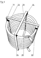
- a guide component 1 with a C-shaped cross-sectional profile receives a fixing component 2 , which is designed as a clamp open on one side, in cross-section 3 of the C-profile and guides the same therein.
- the fixing member 2 takes a pipe 6 , here a smooth tube on.
- the fixing component 2 is displaceable in the longitudinal direction in the guide member 1 .
- the guide member 1 is preferably designed as a metal profile, but it can also be designed as a groove in a base member, for example in a container wall.
- An embodiment of the Fix istsbautells consists in a molding 7, which is approximately U-shaped and has a central recess 8 for receiving pipes.
- the U-shaped recess 8 is formed by lateral legs 11 and 12 , at the front ends 13 and 14 respectively inwardly projecting tabs 15 and 16 are formed.
- a fixing member 7 is inserted from the end face 20 of a guide member 21 in its cross section and can be moved in the guide member 21 .
- the gap 24 can be enlarged by inserting unillustrated fixing spacers between two components or 2. 7 He can also be determined by uniform material formations on the fixing components 2 or 7 .
- a further possibility, not shown for the determination of the gap 24 can also consist in that between the guide member 1, 21 and fixing member 2, 7 form compatible elements are additionally arranged which engage upon reaching certain positions in the guide member and thus the determination of a fixed position is possible.
- FIG. 4 An embodiment of the in Fig. 4 shown assembly uses guide members 21 so that they are mounted back to back and fastened together. This makes it possible to fix a first 25 and a second line 26 with the resulting assembly of guide members 21 and fixing components 2 or 7 .
- first guide component 27 receives a second guide component 28 arranged opposite to it and both are connected to an upper 29 and a lower connecting component 30 .
- a third guide member 31 is arranged at right angles or at any other angle to the first guide member 27 and this opposite a fourth guide member 32 , which are again connected to an upper 33 and a lower connecting member, not shown.
- the upper connecting members 29 and 33 and the lower connecting members may be connected to each other.
- the preparation of the fixation is initially in the way that a prepared guide member 1, 21, 27, 28, 31, 32 equipped with fixing components 2, 7 is and in a subsequent operation in the fixing components 2, 7 lines 23, 25, 26 are pressed.
- Fixierungsbautelle 2, 7 are deformed and try at the end of Eind Wegvorganges by resetting the resulting stresses again reduce. Any remaining residual stresses serve as well as a resulting form-fitting of the fixation of the lines.
- An embodiment of the method may be that a line laid in an arc and fixed in fixing components 2, 7 , which are located in the same guide member again. In this way, a spiral or a cylindrical winding can be fixed with one or more juxtaposed lines.
- An embodiment of the method may be that are assembled in a preceding work step guide members 1, 21 back to back, and a at least one further line is fixed to the mounting or fixing a first line in a subsequent working step on the other side.
- the guide components lie here after completion of the process between the lines.
- a further embodiment of the method is that, in particular, spiral or cylindrical windings of lines are fixed by a first 27 and a second guide member 28, each equipped with fixing components 2, 7 are arranged opposite to each other and after fixing the line be connected in a further operation with an upper 29 and a lower connecting member 30 with each other.
- a further embodiment of the method may consist in that, at an arbitrary angle to the guide components 31, 32, further guide components 34, 35 are arranged, which are each equipped with fixing components 2, 7 . These can also be connected to each other in subsequent operations with connecting components, wherein the guide members 31 and 32 with an upper 33 and a lower connecting member, the guide members 34th and 35 are also connected to an upper 29 and a lower connecting member 30. Likewise, a connection between adjacent connection components can be generated.
- fixations described above and the methods for their preparation are used for fixing lines whose position after installation (fixation) is not exactly predictable or whose position may change due to mechanical and / or thermal influences.
- fixations find particular use for fixing lines at certain distances from each other, which may be individual continuous lines or a plurality of spaced lines running. This is especially the case when spiral or cylindrical coils are created with the leads.
- a preferred form of use is therefore the use of fixation in coils for heat exchangers.
- the invention thus has the advantage that easily and simply and using less additional components, a fixation of lines can be made, which corresponds in particular to the existing conditions of use in heat exchangers.
Landscapes
- Engineering & Computer Science (AREA)
- General Engineering & Computer Science (AREA)
- Mechanical Engineering (AREA)
- Physics & Mathematics (AREA)
- Thermal Sciences (AREA)
- Supports For Pipes And Cables (AREA)
Priority Applications (1)
| Application Number | Priority Date | Filing Date | Title |
|---|---|---|---|
| EP09000934A EP2211079A1 (fr) | 2009-01-23 | 2009-01-23 | Système de fixation pour conduites et procédé de fixation |
Applications Claiming Priority (1)
| Application Number | Priority Date | Filing Date | Title |
|---|---|---|---|
| EP09000934A EP2211079A1 (fr) | 2009-01-23 | 2009-01-23 | Système de fixation pour conduites et procédé de fixation |
Publications (1)
| Publication Number | Publication Date |
|---|---|
| EP2211079A1 true EP2211079A1 (fr) | 2010-07-28 |
Family
ID=40790444
Family Applications (1)
| Application Number | Title | Priority Date | Filing Date |
|---|---|---|---|
| EP09000934A Withdrawn EP2211079A1 (fr) | 2009-01-23 | 2009-01-23 | Système de fixation pour conduites et procédé de fixation |
Country Status (1)
| Country | Link |
|---|---|
| EP (1) | EP2211079A1 (fr) |
Cited By (6)
| Publication number | Priority date | Publication date | Assignee | Title |
|---|---|---|---|---|
| EP2474795A1 (fr) * | 2010-12-30 | 2012-07-11 | TVP Solar S.A. | Panneau thermique solaire sous vide avec boîtier de tubes |
| EP2450729A3 (fr) * | 2010-11-04 | 2012-08-08 | Berthold Sichert GmbH | Système modulaire pour un dispositif de fixation |
| DE102015100227B4 (de) * | 2014-02-03 | 2018-03-22 | Witzenmann Gmbh | Schlauchhaltestruktur für ein Wärmetauschermodul für Warmwasserspeicher |
| CN110823914A (zh) * | 2019-11-02 | 2020-02-21 | 宜春市龙腾机械电气有限公司 | 铠装超导导体焊缝着色检查装备及其检查方法 |
| CN114305113A (zh) * | 2022-01-24 | 2022-04-12 | 石家庄格力电器小家电有限公司 | 一种用于换热器的固定组件、换热器机构和净饮机 |
| EP4664046A1 (fr) * | 2024-06-13 | 2025-12-17 | Witzenmann GmbH | Structure de support de tuyau et module d'échangeur de chaleur |
Citations (8)
| Publication number | Priority date | Publication date | Assignee | Title |
|---|---|---|---|---|
| FR2350492A1 (fr) * | 1976-05-04 | 1977-12-02 | Hilti Ag | Collier pour tubes et cables |
| DD247965A1 (de) | 1986-04-08 | 1987-07-22 | Bauakademie Ddr | Verfahren zur herstellung von rohrbuendeln fuer waermeuebertrager |
| DE3928558A1 (de) | 1989-08-29 | 1991-03-07 | Raimund Dr Rer Nat Oberschmid | Luft-luft-waermetauscher mit rippenrohr-klemmbloecken und spannvorrichtung bes. fuer landwirtschaftliche staelle |
| DE20314766U1 (de) * | 2003-09-22 | 2003-12-11 | Witzenmann Gmbh | Haltevorrichtung für wendelförmige Leitungselemente |
| US20050098697A1 (en) * | 2003-11-06 | 2005-05-12 | C&S Manufacturing Corporation | Adjustable hanger bracket assembly |
| AT7834U1 (de) * | 2004-10-08 | 2005-09-26 | Bremstaller Ges M B H & Co Kg | Wärmetauscher für einen warmwasserbehälter |
| DE202007009023U1 (de) | 2007-06-26 | 2007-10-04 | Az Industrietechnik Gmbh & Co. Kg | Anordnung zur Fixierung von Leitungen |
| DE102007011194B3 (de) * | 2007-03-06 | 2008-09-04 | Winkler, Wolfram, Dipl.-Ing. Dr. | Befestigungsclip zur Befestigung von Rohren |
-
2009
- 2009-01-23 EP EP09000934A patent/EP2211079A1/fr not_active Withdrawn
Patent Citations (8)
| Publication number | Priority date | Publication date | Assignee | Title |
|---|---|---|---|---|
| FR2350492A1 (fr) * | 1976-05-04 | 1977-12-02 | Hilti Ag | Collier pour tubes et cables |
| DD247965A1 (de) | 1986-04-08 | 1987-07-22 | Bauakademie Ddr | Verfahren zur herstellung von rohrbuendeln fuer waermeuebertrager |
| DE3928558A1 (de) | 1989-08-29 | 1991-03-07 | Raimund Dr Rer Nat Oberschmid | Luft-luft-waermetauscher mit rippenrohr-klemmbloecken und spannvorrichtung bes. fuer landwirtschaftliche staelle |
| DE20314766U1 (de) * | 2003-09-22 | 2003-12-11 | Witzenmann Gmbh | Haltevorrichtung für wendelförmige Leitungselemente |
| US20050098697A1 (en) * | 2003-11-06 | 2005-05-12 | C&S Manufacturing Corporation | Adjustable hanger bracket assembly |
| AT7834U1 (de) * | 2004-10-08 | 2005-09-26 | Bremstaller Ges M B H & Co Kg | Wärmetauscher für einen warmwasserbehälter |
| DE102007011194B3 (de) * | 2007-03-06 | 2008-09-04 | Winkler, Wolfram, Dipl.-Ing. Dr. | Befestigungsclip zur Befestigung von Rohren |
| DE202007009023U1 (de) | 2007-06-26 | 2007-10-04 | Az Industrietechnik Gmbh & Co. Kg | Anordnung zur Fixierung von Leitungen |
Cited By (8)
| Publication number | Priority date | Publication date | Assignee | Title |
|---|---|---|---|---|
| EP2450729A3 (fr) * | 2010-11-04 | 2012-08-08 | Berthold Sichert GmbH | Système modulaire pour un dispositif de fixation |
| DE102011012438B4 (de) * | 2010-11-04 | 2016-04-14 | Berthold Sichert Gmbh | Baukasten für Befestigungsvorrichtung |
| EP2474795A1 (fr) * | 2010-12-30 | 2012-07-11 | TVP Solar S.A. | Panneau thermique solaire sous vide avec boîtier de tubes |
| US9404676B2 (en) | 2010-12-30 | 2016-08-02 | Tvp Solar S.A. | Vacuum solar thermal panel with pipe housing |
| DE102015100227B4 (de) * | 2014-02-03 | 2018-03-22 | Witzenmann Gmbh | Schlauchhaltestruktur für ein Wärmetauschermodul für Warmwasserspeicher |
| CN110823914A (zh) * | 2019-11-02 | 2020-02-21 | 宜春市龙腾机械电气有限公司 | 铠装超导导体焊缝着色检查装备及其检查方法 |
| CN114305113A (zh) * | 2022-01-24 | 2022-04-12 | 石家庄格力电器小家电有限公司 | 一种用于换热器的固定组件、换热器机构和净饮机 |
| EP4664046A1 (fr) * | 2024-06-13 | 2025-12-17 | Witzenmann GmbH | Structure de support de tuyau et module d'échangeur de chaleur |
Similar Documents
| Publication | Publication Date | Title |
|---|---|---|
| DE3640919C2 (fr) | ||
| EP2211079A1 (fr) | Système de fixation pour conduites et procédé de fixation | |
| DE1599041C2 (de) | Vorrichtung zur Führung flexibler Versorgungsleitungen in Röntgenanlagen | |
| EP2292988A2 (fr) | Dispositif de fixation pour la fixation de panneaux solaires sur un rail de montage | |
| EP2009337B1 (fr) | Agencement et procédé de fixation de conduites | |
| DE3034888A1 (de) | Aus einem flexiblen oder steifen kunststoff bestehendes rohr zum transport eines waermetraegers | |
| DE2853665C3 (de) | Wärmeübertragungssystem | |
| EP1413836B1 (fr) | Capteur solaire | |
| DE20314766U1 (de) | Haltevorrichtung für wendelförmige Leitungselemente | |
| WO2014086332A1 (fr) | Système d'isolation et procédé permettant d'établir une isolation thermique et acoustique, sans contact | |
| DE2715394A1 (de) | Halterung fuer heizungsrohre | |
| DE102009045484A1 (de) | Leitungsabhängeeinrichtung | |
| DE3333442A1 (de) | Rohrhalter | |
| EP0555187A1 (fr) | Rail de fixation, notamment pour câbles et canalisations de câble | |
| DE4344144C2 (de) | Montageschiene für Installationen in Gebäuden | |
| DE202009000896U1 (de) | Fixierungssystem für Leitungen und Fixierung | |
| CH635666A5 (en) | Ceiling radiator heating unit in hall-like rooms | |
| DE3421095C2 (de) | Dämpfungshalterung, insbesondere für dynamischen Belastungen und beträchtlichen Temperaturschwankungen ausgesetzte dünnwandige Rohrleitungen | |
| DE2607474A1 (de) | Rohrleitung fuer fussbodenheizung | |
| DE102021126428A1 (de) | Modular aufgebautes Kühlleitungssystem, insbesondere für Batterien von E-Fahrzeugen | |
| LU506101B1 (de) | Verfahren und system zum aufhängen von rohren an einer decke in einem raum | |
| AT7834U1 (de) | Wärmetauscher für einen warmwasserbehälter | |
| DE102023103212B3 (de) | Halteelement zum Fixieren der Kabel einer Photovoltaikanlage | |
| DE4239262A1 (en) | Holder to guide, bend and retain shape of flexible pipes - consists of spiral coil of steel wire of uniform interval dia. which supports a pipe passed through and then bent as required | |
| DE102012216726B4 (de) | Haltevorrichtung für Leitungselemente |
Legal Events
| Date | Code | Title | Description |
|---|---|---|---|
| PUAI | Public reference made under article 153(3) epc to a published international application that has entered the european phase |
Free format text: ORIGINAL CODE: 0009012 |
|
| AK | Designated contracting states |
Kind code of ref document: A1 Designated state(s): AT BE BG CH CY CZ DE DK EE ES FI FR GB GR HR HU IE IS IT LI LT LU LV MC MK MT NL NO PL PT RO SE SI SK TR |
|
| AX | Request for extension of the european patent |
Extension state: AL BA RS |
|
| AKY | No designation fees paid | ||
| STAA | Information on the status of an ep patent application or granted ep patent |
Free format text: STATUS: THE APPLICATION IS DEEMED TO BE WITHDRAWN |
|
| 18D | Application deemed to be withdrawn |
Effective date: 20110129 |