EP2216213B1 - Airbagabdeckung und Airbagvorrichtung - Google Patents
Airbagabdeckung und Airbagvorrichtung Download PDFInfo
- Publication number
- EP2216213B1 EP2216213B1 EP10000801A EP10000801A EP2216213B1 EP 2216213 B1 EP2216213 B1 EP 2216213B1 EP 10000801 A EP10000801 A EP 10000801A EP 10000801 A EP10000801 A EP 10000801A EP 2216213 B1 EP2216213 B1 EP 2216213B1
- Authority
- EP
- European Patent Office
- Prior art keywords
- airbag
- door
- door portion
- disposed
- cover
- Prior art date
- Legal status (The legal status is an assumption and is not a legal conclusion. Google has not performed a legal analysis and makes no representation as to the accuracy of the status listed.)
- Not-in-force
Links
- 230000000903 blocking effect Effects 0.000 claims description 4
- 238000012986 modification Methods 0.000 description 31
- 230000004048 modification Effects 0.000 description 31
- 238000010586 diagram Methods 0.000 description 7
- 102100040678 Programmed cell death protein 1 Human genes 0.000 description 5
- 101710089372 Programmed cell death protein 1 Proteins 0.000 description 5
- 210000002414 leg Anatomy 0.000 description 4
- 230000002708 enhancing effect Effects 0.000 description 3
- 230000000694 effects Effects 0.000 description 2
- 210000003127 knee Anatomy 0.000 description 2
- 230000000116 mitigating effect Effects 0.000 description 2
- 230000001133 acceleration Effects 0.000 description 1
- 230000001419 dependent effect Effects 0.000 description 1
- 238000005259 measurement Methods 0.000 description 1
- 238000000034 method Methods 0.000 description 1
- 230000001681 protective effect Effects 0.000 description 1
- 230000000717 retained effect Effects 0.000 description 1
- 230000000630 rising effect Effects 0.000 description 1
Images


Classifications
-
- B—PERFORMING OPERATIONS; TRANSPORTING
- B60—VEHICLES IN GENERAL
- B60R—VEHICLES, VEHICLE FITTINGS, OR VEHICLE PARTS, NOT OTHERWISE PROVIDED FOR
- B60R21/00—Arrangements or fittings on vehicles for protecting or preventing injuries to occupants or pedestrians in case of accidents or other traffic risks
- B60R21/02—Occupant safety arrangements or fittings, e.g. crash pads
- B60R21/16—Inflatable occupant restraints or confinements designed to inflate upon impact or impending impact, e.g. air bags
- B60R21/20—Arrangements for storing inflatable members in their non-use or deflated condition; Arrangement or mounting of air bag modules or components
- B60R21/215—Arrangements for storing inflatable members in their non-use or deflated condition; Arrangement or mounting of air bag modules or components characterised by the covers for the inflatable member
- B60R21/2165—Arrangements for storing inflatable members in their non-use or deflated condition; Arrangement or mounting of air bag modules or components characterised by the covers for the inflatable member characterised by a tear line for defining a deployment opening
- B60R21/21656—Steering wheel covers or similar cup-shaped covers
-
- B—PERFORMING OPERATIONS; TRANSPORTING
- B60—VEHICLES IN GENERAL
- B60R—VEHICLES, VEHICLE FITTINGS, OR VEHICLE PARTS, NOT OTHERWISE PROVIDED FOR
- B60R21/00—Arrangements or fittings on vehicles for protecting or preventing injuries to occupants or pedestrians in case of accidents or other traffic risks
- B60R21/02—Occupant safety arrangements or fittings, e.g. crash pads
- B60R21/16—Inflatable occupant restraints or confinements designed to inflate upon impact or impending impact, e.g. air bags
- B60R21/20—Arrangements for storing inflatable members in their non-use or deflated condition; Arrangement or mounting of air bag modules or components
- B60R21/201—Packaging straps or envelopes for inflatable members
-
- B—PERFORMING OPERATIONS; TRANSPORTING
- B60—VEHICLES IN GENERAL
- B60R—VEHICLES, VEHICLE FITTINGS, OR VEHICLE PARTS, NOT OTHERWISE PROVIDED FOR
- B60R21/00—Arrangements or fittings on vehicles for protecting or preventing injuries to occupants or pedestrians in case of accidents or other traffic risks
- B60R21/02—Occupant safety arrangements or fittings, e.g. crash pads
- B60R21/16—Inflatable occupant restraints or confinements designed to inflate upon impact or impending impact, e.g. air bags
- B60R21/23—Inflatable members
- B60R21/239—Inflatable members characterised by their venting means
-
- B—PERFORMING OPERATIONS; TRANSPORTING
- B60—VEHICLES IN GENERAL
- B60R—VEHICLES, VEHICLE FITTINGS, OR VEHICLE PARTS, NOT OTHERWISE PROVIDED FOR
- B60R21/00—Arrangements or fittings on vehicles for protecting or preventing injuries to occupants or pedestrians in case of accidents or other traffic risks
- B60R21/02—Occupant safety arrangements or fittings, e.g. crash pads
- B60R21/16—Inflatable occupant restraints or confinements designed to inflate upon impact or impending impact, e.g. air bags
- B60R21/20—Arrangements for storing inflatable members in their non-use or deflated condition; Arrangement or mounting of air bag modules or components
- B60R21/215—Arrangements for storing inflatable members in their non-use or deflated condition; Arrangement or mounting of air bag modules or components characterised by the covers for the inflatable member
- B60R2021/21543—Arrangements for storing inflatable members in their non-use or deflated condition; Arrangement or mounting of air bag modules or components characterised by the covers for the inflatable member with emblems
Definitions
- the present invention relates to airbag apparatuses mounted on vehicles such as automobiles, and more specifically, it relates to an airbag apparatus characterized by means for splitting open an airbag cover.
- Vehicles such as automobiles are typically provided with an airbag apparatus that inflates and deploys an airbag for absorbing an impact exerted on an occupant in the passenger compartment in the event of a collision or abrupt deceleration.
- airbag apparatuses include a driver side airbag apparatus provided inside a steering wheel, a passenger side airbag apparatus provided inside an instrument panel, a side airbag apparatus provided inside the side of the vehicle or the vehicle seat, a curtain airbag apparatus provided inside the upper part of the door, a knee airbag apparatus provided so as to protect the knee of the occupant, and a pedestrian protective airbag apparatus provided under the hood of the vehicle and the like.
- These airbag apparatuses typically have an airbag that is normally in a folded state and inflates and deploys in the event of an emergency, an inflator that supplies gas to the airbag, a retainer that houses the airbag, and an airbag cover that normally conceals the airbag and, in the event of an emergency, splits open a door portion thereof for releasing the airbag into the passenger compartment.
- the airbag cover is a resin-molded, thin-walled plate-like component having a groove called a tear line formed on the back face thereof.
- a tear line consists of a groove formed to be thin-walled for allowing the airbag to easily split open the airbag cover.
- a door portion formed by splitting open the airbag cover is rotatably supported by a hinge portion, a portion connecting with the airbag cover, forming a release section through which the airbag is released (see PD 1 and PD 2).
- An airbag cover described in PD 1 is configured so as to split open in a substantially H-shape and is also configured in such a manner that, when the door portion is divided into two portions, these door portions rotate upward and downward, respectively.
- an airbag cover described in PD 2 is configured so as to split open in a substantially mountain shape and is also configured in such a manner that, when the door portion is divided into three portions, these door portions rotate in the upper left direction, in the upper right direction, and in the downward direction, respectively.
- JP 2006-076322 A discloses an airbag cover with two door portions, both door portions being configured to rotate sideward when the airbag cover splits open the door portions for releasing the airbag.
- An airbag may have an exhaust port called a vent hole formed therein.
- a vent hole has a function of preventing the inside pressure of airbags from rising to an excessively high level or, when an occupant comes into contact with an inflated airbag, mitigating an impact on the occupant by releasing the gas inside of the airbag.
- the conditions for forming the vent hole are determined by the airbag size, capacity, mounting position, vehicle type and the like.
- a driver side airbag disclosed in PD 1 and PD 2 may have a vent hole formed in a space created between the upper side portion of the airbag cover and the steering wheel.
- an airbag cover described in PD 1 and PD 2 described above encounters a problem that rotatable door portions provided at the upper side portion thereof narrow a space formed between the upper side portion and the steering wheel, which restricts the flexibility in design of the vent hole to be formed in an airbag.
- Such a problem is not limited to driver side airbags, and is a common problem encountered when an attempt is made to form a vent hole around the airbag cover.
- the present invention has been achieved in light of the foregoing and an object thereof is to provide an airbag apparatus which can enhance the flexibility in design of a vent hole to be formed in an airbag.
- the present invention provides an airbag apparatus comprising an airbag that is normally in a folded state and inflates and deploys in the event of an emergency, the airbag having a vent hole that can release gas supplied to an inside thereof, an inflator that supplies gas to the airbag; a retainer that houses the airbag, and an airbag cover that normally conceals the airbag and, in the event of an emergency, splits open a plurality of door portions thereof for releasing the airbag into a passenger compartment, wherein the vent hole of the airbag is disposed along a side surface portion of the airbag cover in a space between an upper side portion of the airbag cover and an annular rim of a steering wheel when the airbag apparatus is disposed in the steering wheel; and each door portion is configured so as not to rotate to the side of the side surface portion and is configured not to rotate beyond a line T passing through the top of the airbag cover, thereby preventing each rotating door portion from blocking the vent hole upon splitting open.
- the airbag apparatus has door portions that are configured so as not to rotate to the side surface portion where a vent hole is disposed, thereby preventing each rotating door portion from blocking the vent hole even if the airbag inflates and deploys in the event of an emergency. This allows the vent hole to be disposed along the side surface portion of the airbag cover, thereby enhancing the flexibility in design of the vent hole to be formed in the airbag.
- double doors allows the airbag cover to promptly, smoothly split open, thereby allowing the efficient inflation and deployment of the airbag.
- an ornament such as an emblem or the like to be rotated together with the door portion allows a larger space inside the airbag cover, namely, a larger space for housing the airbag to be secured.
- placement of the ornament on the third door portion allows the first door portion and second door portion to be promptly, smoothly opened in the same manner as double doors while allowing the ornament to be rotated together with the third door portion.
- use of the airbag cover as a driver side airbag cover can provide advantages above more efficiently.
- the airbag cover can be split open promptly, smoothly by adjusting the location of a predetermined fracture portion in the wrapping component or the method of folding the airbag, thereby allowing the airbag to be efficiently inflated and deployed.
- Fig. 1 is a diagram showing an airbag apparatus according to the present invention.
- Fig. 1(A) is a front view.
- Fig. 1(B) is a sectional view taken along the line B-B of Fig. 1(A) .
- Fig. 2 is a diagram showing the effect of an airbag apparatus according to the present invention.
- Fig. 2(A) is a front view of an airbag as inflated and deployed.
- Fig. 2(B) is a rear view of an airbag as inflated and deployed.
- An airbag apparatus shown in Fig. 1 and Fig. 2 , has an airbag 1 that is normally in a folded state and inflates and deploys in the event of an emergency, an inflator 2 that supplies gas to the airbag 1, a retainer 3 that houses the airbag 1, and an airbag cover 4 that normally conceals the airbag 1 and, in the event of an emergency, splits open a door portion 41 (a first door portion 41 a, a second door portion 41b, and a third door portion 41c) thereof for releasing the airbag 1 into the passenger compartment, wherein the airbag 1 has a vent hole 11 that can release gas supplied to the inside thereof, and the vent hole 11 is disposed along a side surface portion 45 of the airbag cover 4, and the door portion 41 (the first door portion 4 1 a, the second door portion 41b, and the third door portion 41c) is configured so as not to rotate to the side of the side surface portion 45.
- An airbag apparatus shown in Fig. 1 and Fig. 2 is a driver side airbag apparatus, which is disposed in a steering wheel 5.
- the steering wheel 5 includes an annular rim 51 constituting a handle portion, a hub 52 connected to a steering shaft, and a spoke 53 connecting the rim 51 to the hub 52.
- the steering wheel having three spokes 53 is shown. Diagrams showing the steering shaft and the steering column are omitted in Fig. 1(B) .
- the airbag cover 4 is connected so as to cover the hub 52, in which the airbag 1, the inflator 2, and the retainer 3 are disposed.
- the airbag 1 is normally housed in a folded state in a space formed by the retainer 3 and the airbag cover 4.
- the airbag 1 is inwardly folded.
- the airbag 1 is wrapped with a wrapping component 6 while housed in such a space, and the shape of the airbag 1 in a folded state is retained by the wrapping component 6.
- the wrapping component 6 has a predetermined fracture portion 61 formed therein, which, in the event of an emergency, fractures for allowing the airbag to be released.
- the wrapping component 6 may consist of a cloth-like or a strap-like component.
- the inflator 2 has a substantially cylindrical outer shape and has gas jetting ports formed at a circumferential side surface of its end contained in the airbag 1.
- the inflator 2 is fit in an opening formed in the retainer 3 and is secured by a flange portion 21.
- the inflator 2 is connected to an electronic control unit (ECU) (not illustrated) and is controlled on the basis of measurements obtained by an acceleration sensor or the like.
- ECU electronice control unit
- the inflator 2 is ignited by an ignition current from the ECU, causing an agent contained in the inflator 2 to combust and produce gas which is supplied to the airbag 1.
- the retainer 3, which retains the airbag 1 and the inflator 2 in an integral manner, is a component for housing the airbag 1 in the airbag cover 4.
- the retainer 3 has an opening formed substantially in the center thereof, into which the inflator 2 is inserted.
- the retainer 3 has fasteners 31 such as bolts and nuts disposed thereon, which hold the flange portion 21 of the inflator 2 and the airbag 1 therebetween.
- the retainer 3 is secured to the hub 52 with fasteners 32 such as bolts and nuts disposed at the leg portion thereof.
- the retainer 3 may be secured by locking a plurality of hooks formed at the outer circumference of the retainer 3 into holes formed at leg portions 42 of the airbag cover 4.
- the airbag cover 4 which is disposed in the hub 52, is a component for covering the hub 52 and the airbag 1. More specifically, the airbag cover 4 is formed in a substantially cup-like shape so as to be able to cover the hub 52, and has the leg portion 42 formed so as to stand upright on an inner circumferential surface thereof, the leg portion 42 creating a space for housing the airbag 1. Although not illustrated, when the airbag cover 4 is used as a horn switch, the airbag cover 4 is disposed so as to be slidable on the hub 52.
- the airbag cover 4 is also a component for constituting a vehicle interior surface and, therefore, is provided on the front face thereof with an ornament 43 such as an emblem.
- the airbag cover 4 has a thin-wall tear line 44 formed at the back face thereof in a predetermined shape so as to split open into the door portion 41 (the first door portion 41 a, the second door portion 41b, and the third door portion 41c).
- the tear line 44 is formed, for example, in a combined shape of a substantially T shape and a substantially inverted U shape.
- the door portion 41 consists of the first door portion 41 a and the second door portion 41b which are configured to open in the same manner as double doors along the side surface portion 45 and the third door portion 41c which is configured to be rotatable to the opposite side of the side surface portion 45, wherein the third door portion 41 c has an ornament 43 to be disposed on the surface of the airbag cover 4 provided thereon.
- the airbag apparatus In the event of an emergency (in which the ECU detects or predicts a crash or abrupt deceleration of a vehicle) the airbag apparatus provided with the airbag cover 4 causes the inflator 2 to supply gas to the airbag 1, which then inflates and presses against the rear face of the airbag cover 4.
- the airbag cover 4 splits open along the tear line 44 since a portion in which the tear line 44 is formed is low in strength, causing the first door portion 41 a, the second door portion 41b, and the third door portion 41 c to rotate about portions where no tear line 44 is formed as hinge portions 46a, 46b, and 46c, respectively, so as to open outward. Accordingly, as shown in Fig.
- the first door portion 41 a and the second door portion 41b open in the same manner as double doors along the side surface portion 45, while the third door portion 41c rotates to the opposite side of the side surface portion 45 together with the ornament 43.
- the first door portion 41 a, the second door portion 41 b, and the third door portion 41 c are configured to be not able to rotate to the side of the side surface portion 45, but deploy in a substantially T shape.
- the first door portion 41 a and the second door portion 41b rotate so as not to go beyond a line T passing through the top of the airbag cover 4.
- the airbag 1 is indicated by dotted lines and the illustration of the inflator 2 is omitted in Fig. 2(A) .
- the vent hole 11 is disposed along the side surface portion 45 of the airbag cover 4.
- the vent hole 11 has the function for reducing the inner pressure of the airbag 1 as well as mitigating an impact on an occupant, and the conditions for its location, size, quantity, or the like are determined by the conditions for the shape, capacity, or the like of the airbag 1 to be used.
- the present invention prevents the rotating door portion 41 from blocking the space encompassed by the steering wheel 5.
- one, two, or four or more vent holes 11 may be formed although three vent holes 11 are formed in Fig. 2(B) which is given just as an example.
- the present invention can secure a sufficiently wide space in the steering wheel 5 by preventing the door portion 41 from rotating to the side of the side surface portion 45, thereby enhancing the flexibility in design of the vent hole 11 to be formed in an airbag 1. Accordingly, the airbag cover 4 and the airbag apparatus according to the present invention can employ the unit of the same shape or the same configuration, irrespective of the number of the vent holes 11 formed therein, which is excellent in terms of convenience.
- Fig. 3 is a sectional view showing an example of modifications to an airbag apparatus according to the present invention.
- Fig. 3(A) shows a first example of modifications
- Fig. 3(B) shows a second example of modifications
- Fig. 3(C) shows a third example of modifications.
- Fig. 4 is a front view showing an example of modifications to an airbag apparatus according to the present invention.
- Fig. 4(A) shows a fourth example of modifications
- Fig. 4(B) shows a fifth example of modifications
- Fig. 4(C) shows a sixth example of modifications
- Fig. 4(D) shows a seventh example of modifications.
- the reference numerals and symbols in these figures refer to the same components as those with the same reference numerals and symbols in Fig. 1 , and repeated descriptions of the same components are omitted.
- the first example of modifications shown in Fig. 3(A) includes the predetermined fracture portion 61 of the wrapping component 6 formed so as to be disposed at a position S close to a portion where the door portion 41 begins to split open.
- the position S close to a portion where the door portion 41 begins to split open refers to, for example, a portion enclosed by dashed-dotted lines in Fig. 3(A) and, more specifically, a portion close to a contact point (upper portion of the ornament 43) among the first door portion 41a, the second door portion 41b, and the third door portion 41c. Pressing against this portion allows the airbag cover 4 to effectively split open into the first door portion 41 a, the second door portion 41b, and the third door portion 41c.
- the airbag 1 is enclosed by the wrapping component 6 for retaining the shape thereof, and begins to inflate and deploy when the wrapping component 6 splits open starting at the predetermined fracture point 61. Accordingly, making the predetermined fracture portion 61 coincident with the portion where the door portion 41 begins to split open allows the airbag cover 4 to split open promptly, smoothly, thereby allowing the airbag 1 to effectively inflate and deploy.
- the second example of modifications shown in Fig. 3(B) includes the airbag 1 folded in such a manner that the end portion 12 of the airbag 1 is disposed at the position S close to a portion where the door portion 41 begins to split open.
- the end portion 12 of the airbag 1 refers to a portion on which a force pressing against the rear face of the airbag cover 4 at the time of inflation of the airbag 1 tends to initially act.
- a portion located immediately above a communicating portion 13 is the end portion 12 of the airbag 1. Disposing the end portion 12 immediately below the position S allows the airbag cover 4 to split open promptly and smoothly, thereby allowing the airbag 1 to effectively inflate and deploy.
- the third example of modifications shown in Fig. 3(C) includes the second example of modifications described above with the end of the airbag 1 being accordion-folded.
- the end portion 12 of the airbag 1 is a portion on which a force pressing against the rear face of the airbag cover 4 tends to initially act.
- the way in which the airbag 1 is folded as shown in Figs. 3(B) and 3(C) is given just as an example, and roll folding or a combination of inward folding and accordion folding may be used. Also, inward folding, accordion folding, or roll folding may be followed by vertical folding for reduction of volume.
- the fourth example of modifications shown in Fig. 4(A) includes the door portion 41 that consists of the first door portion 41 a, the second door portion 41 b, and the third door portion 41 c, wherein the ornament 43 such as an emblem is disposed on the second door portion 41b.
- the tear line 44 having a substantially T shape has its vertical section formed in the shape of a crank. This arrangement also prevents the door portion 41 from rotating to the side of the side surface portion 45.
- the ornament 43 may be disposed on the first door portion 41a, instead of the second door portion 41b.
- the fifth example of modifications shown in Fig. 4(B) includes the door portion 41 that consists of the first door portion 41a and the second door portion 41b, wherein the ornament 43 is disposed on the second door portion 41b.
- the tear line 44 is formed in a substantially H shape, whose vertical section has a convex portion formed therein. This arrangement also prevents the door portion 41 from rotating to the side of the side surface portion 45.
- the ornament 43 may be disposed on the first door portion 41 a instead of the second door portion 41b.
- the sixth example of modifications shown in Fig. 4(C) includes the door portion 41 which consists of the first door portion 41a only, wherein the ornament 43 is disposed on the first door portion 41 a.
- the tear line 44 is formed in a substantially inverted C shape. This arrangement also prevents the door portion 41 from rotating to the side of the side surface portion 45.
- the door portion 41 may consist of the second door portion 41b only.
- the seventh example of modifications shown in Fig. 4(D) includes the door portion 41 which consists of the third door portion 41 c only, wherein the ornament 43 is disposed on the third door portion 41 c.
- the tear line 44 is formed in a substantially inverted U shape. This arrangement also prevents the door portion 41 from rotating to the side of the side surface portion 45.
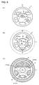
- FIG. 5 is a diagram showing an airbag apparatus according to the second embodiment of the present invention.
- Fig. 5(A) is a front view.
- Fig. 5(B) is a front view of an airbag as inflated and deployed.
- Fig. 5(C) is a rear view of an airbag as inflated and deployed.
- the reference numerals and symbols in these figures refer to the same components as those with the same reference numerals and symbols in Fig. 1 , and repeated descriptions of the same components are omitted.
- the steering wheel 5 has a different shape. As shown in Fig. 5(A) , the steering wheel 5 has four spokes 53.
- the airbag cover 4 and the airbag apparatus according to the present invention can be easily applied to the steering wheel 5 having such a shape.
- the airbag cover 4 is configured to have the tear line 44 formed at the rear face thereof in a predetermined shape so as to split open into the door portion 41 (the first door portion 41a, the second door portion 41b, and the third door portion 41 c).
- the airbag cover 4 splits open along the tear line 44. Then, the first door portion 41 a, the second door portion 41b, and the third door portion 41 c rotate about the hinge portions 46a, 46b, and 46c, respectively, wherein the first door portion 41 a and the second door portion 41b opens in the same manner as double doors along the side surface portion 45, and the third door portion 41 c rotates to the opposite side of the side surface portion 45 together with the ornament 43, as shown in Fig. 5(B) .
- the rotating door portion 41 of the airbag cover 4 is configured so as not to block a space enclosed by the steering wheel 5, thereby securing a sufficiently wide space encompassed by the rim 51, the hub 52, and the spoke 53 of the steering wheel 5 and thereby enhancing the flexibility in design of the vent hole 11 to be formed in an airbag 1.
- one, two, or four or more vent holes 11 may be formed although three vent holes 11 are formed in Fig. 5(C) which is given just as an example.
Landscapes
- Engineering & Computer Science (AREA)
- Mechanical Engineering (AREA)
- Air Bags (AREA)
Claims (7)
- Airbagvorrichtung, welche in einem Lenkrad (5) angeordnet ist, umfassend:einen Airbag (1), der sich normalerweise in einem gefalteten Zustand befindet und in einem Notfall entfaltet und aufgeblasen wird, wobei der Airbag (1) ein Luftloch (11) aufweist, welches Gas, das einem Innenraum des Airbags zugeführt wird, abgeben kann;eine Aufblaseinrichtung (2), die dem Airbag (1) Gas zuführt;eine Halterung (3), in der der Airbag (1) untergebracht ist; undeine Airbagabdeckung (4), die normalerweise den Airbag (1) bedeckt und in einem Notfall mehrere Türabschnitte (41 a-c) davon aufbricht, um den Airbag (1) in einen Fahrgastraum freizugeben,dadurch gekennzeichnet,
dass das Luftloch (11) des freigegebenen Airbags (1) entlang eines seitlichen Oberflächenabschnitts (45) der Airbagabdeckung (4) in einem Zwischenraum zwischen einem oberen Seitenabschnitt der Airbagabdeckung (4) und einem ringförmigen Rand (51) des Lenkrads (5) angeordnet ist, und
dass jeder Türabschnitt (41 a-c) derart ausgestaltet ist, dass er nicht zu derjenigen Seite des seitlichen Oberflächenabschnitts (45), wo das Luftloch (11) des freigegebenen Airbags (1) angeordnet ist, und nicht über eine T-Linie, welche durch die Oberseite der Airbagabdeckung (4) verläuft, gedreht wird, wodurch jeder sich drehende Türabschnitt (41a-c) daran gehindert wird, beim Aufbrechen das Luftloch (11) zu blockieren. - Airbagvorrichtung nach Anspruch 1, wobei die Türabschnitte (41a-c) derart ausgestaltet sind, dass sie sich wie Doppeltüren entlang des seitlichen Oberflächenabschnitts (45) öffnen.
- Airbagvorrichtung nach Anspruch 1 oder 2, wobei einer der Türabschnitte ein auf der Oberfläche der Airbagabdeckung (4) anzuordnendes Ornament (43) aufweist, und wobei sich das Ornament (43) zusammen mit dem einen Türabschnitt (41a-c) dreht.
- Airbagvorrichtung nach einem der Ansprüche 1-3, wobei die mehreren Türabschnitte (41a-c) aus einem ersten Türabschnitt (41 a) und einem zweiten Türabschnitt (41 b), welche derart ausgestaltet sind, dass sie sich wie Doppeltüren entlang des seitlichen Oberflächenabschnitts (45) öffnen, und einem dritten Türabschnitt (41 c), welcher ausgestaltet ist, um zu der entgegengesetzten Seite des seitlichen Oberflächenabschnitts (45) gedreht werden zu können, besteht, wobei der dritte Türabschnitt (41 c) ein auf der Oberfläche der Airbagabdeckung (4) anzuordnendes Ornament (43) aufweist.
- Airbagvorrichtung nach einem der Ansprüche 1-4, wobei die Airbagabdeckung (4) eine fahrerseitige Airbagabdeckung ist, welche in einer Nabe (52) des Lenkrads (5) angeordnet ist.
- Airbagvorrichtung nach einem der Ansprüche 1-5, wobei der Airbag (1) eine umhüllende Komponente (6) aufweist, die normalerweise die Form des Airbags (1) bewahrt und einen darin ausgebildeten bestimmten Bruchabschnitt (61) aufweist, welcher in einem Notfall bricht, um eine Freigabe des Airbags (1) zu ermöglichen, und wobei der bestimmte Bruchabschnitt (61) in der Nähe eines Abschnitts (S) angeordnet ist, wo die Türabschnitte (41 a-c) aufzubrechen beginnen.
- Airbagvorrichtung nach einem der Ansprüche 1-6, wobei der Airbag (1) derart gefaltet ist, dass ein Ende (12) des Airbags (1) in der Nähe eines Abschnitts (S), wo die Türabschnitte (41a-c) aufzubrechen beginnen, angeordnet ist.
Applications Claiming Priority (1)
| Application Number | Priority Date | Filing Date | Title |
|---|---|---|---|
| JP2009026069A JP5322275B2 (ja) | 2009-02-06 | 2009-02-06 | エアバッグ装置 |
Publications (2)
| Publication Number | Publication Date |
|---|---|
| EP2216213A1 EP2216213A1 (de) | 2010-08-11 |
| EP2216213B1 true EP2216213B1 (de) | 2012-12-12 |
Family
ID=42062158
Family Applications (1)
| Application Number | Title | Priority Date | Filing Date |
|---|---|---|---|
| EP10000801A Not-in-force EP2216213B1 (de) | 2009-02-06 | 2010-01-27 | Airbagabdeckung und Airbagvorrichtung |
Country Status (3)
| Country | Link |
|---|---|
| US (1) | US20100201105A1 (de) |
| EP (1) | EP2216213B1 (de) |
| JP (1) | JP5322275B2 (de) |
Families Citing this family (13)
| Publication number | Priority date | Publication date | Assignee | Title |
|---|---|---|---|---|
| ITBO20080013A1 (it) * | 2008-01-09 | 2009-07-10 | Ferrari Spa | Coperchio per un airbag |
| JP2012071724A (ja) * | 2010-09-29 | 2012-04-12 | Toyoda Gosei Co Ltd | エアバッグ装置用カバー |
| JP5812247B2 (ja) * | 2011-02-24 | 2015-11-11 | 富士重工業株式会社 | 内装部材 |
| JP2014213749A (ja) * | 2013-04-25 | 2014-11-17 | 日本プラスト株式会社 | エアバッグ |
| JP6036630B2 (ja) * | 2013-09-30 | 2016-11-30 | 豊田合成株式会社 | ステアリングホイール用エアバッグカバー |
| WO2015120039A1 (en) * | 2014-02-06 | 2015-08-13 | Key Safety Systems Inc. | Driver side airbag module with improved vent |
| DE102014013702B4 (de) * | 2014-09-16 | 2018-02-08 | Autoliv Development Ab | Abdeckelement für ein Gassackmodul und Gassackmodul mit einem solchen Abdeckelement |
| JP6422738B2 (ja) * | 2014-10-31 | 2018-11-14 | 芦森工業株式会社 | エアバッグ装置 |
| US11865993B2 (en) * | 2019-06-18 | 2024-01-09 | Autoliv Development Ab | Driver's seat airbag device |
| US11794681B2 (en) * | 2019-09-17 | 2023-10-24 | Autoliv Development Ab | Driver seat airbag device |
| KR102885990B1 (ko) * | 2020-09-01 | 2025-11-12 | 현대모비스 주식회사 | 엠블렘이 장착된 운전석 에어백 |
| KR102522188B1 (ko) * | 2020-09-15 | 2023-04-14 | 현대모비스 주식회사 | 조명장치가 구비된 운전자 에어백 모듈 |
| KR102914651B1 (ko) | 2020-12-01 | 2026-01-16 | 현대모비스 주식회사 | 스티어링휠용 에어백 커버 구조 |
Citations (2)
| Publication number | Priority date | Publication date | Assignee | Title |
|---|---|---|---|---|
| US20040130131A1 (en) * | 2003-01-07 | 2004-07-08 | Thomas Scott David | Styling flexible driver air bag module and method of making same |
| JP2006076322A (ja) * | 2004-09-07 | 2006-03-23 | Mazda Motor Corp | エアバッグ装置を備えたステアリングホイール |
Family Cites Families (44)
| Publication number | Priority date | Publication date | Assignee | Title |
|---|---|---|---|---|
| US4966388A (en) * | 1989-05-25 | 1990-10-30 | Collision Safety Engineering Inc. | Inflatable structures for side impact crash protection |
| US5351977A (en) * | 1992-11-03 | 1994-10-04 | Trw Inc. | Externally vented airbag assembly |
| JP3467114B2 (ja) * | 1995-03-29 | 2003-11-17 | 日本プラスト株式会社 | エアバッグ装置 |
| WO1997006984A1 (fr) * | 1995-08-21 | 1997-02-27 | Toyo Tire & Rubber Co., Ltd. | Dispositif air bag |
| US5669628A (en) * | 1996-04-08 | 1997-09-23 | Morton International, Inc. | Air bag cushion protection during both normal and out of position deployments |
| JPH106899A (ja) * | 1996-04-26 | 1998-01-13 | Nippon Plast Co Ltd | エアバッグ装置およびエアバッグの折畳方法 |
| GB2326624B (en) * | 1996-09-30 | 2001-01-31 | Nihon Plast Co Ltd | Air-bag device |
| US5893581A (en) * | 1996-11-22 | 1999-04-13 | General Motors Corporation | Air bag cover |
| JP3144354B2 (ja) * | 1997-08-26 | 2001-03-12 | 株式会社デンソー | エアバッグ |
| JP3478974B2 (ja) * | 1998-07-22 | 2003-12-15 | 日本プラスト株式会社 | 自動車用ステアリングホイール |
| JP4032544B2 (ja) * | 1998-12-18 | 2008-01-16 | 日本プラスト株式会社 | エアバッグ装置 |
| DE29913741U1 (de) * | 1999-08-06 | 1999-12-16 | TRW Automotive Safety Systems GmbH & Co. KG, 63743 Aschaffenburg | Abdeckung für einen Gassack eines Fahrzeuginsassen-Rückhaltesystems |
| US6422602B1 (en) * | 1999-10-14 | 2002-07-23 | Toyoda Gosei Co., Ltd. | Air bag in air bag system |
| JP4385472B2 (ja) * | 2000-02-28 | 2009-12-16 | タカタ株式会社 | 運転席用エアバッグ装置 |
| US6247722B1 (en) * | 2000-03-31 | 2001-06-19 | Delphi Technologies, Inc. | Air bag cover with hidden tear seams |
| US6626458B2 (en) * | 2000-09-26 | 2003-09-30 | Toyoda Gosei Co., Ltd. | Steering wheel having airbag apparatus |
| US6502852B2 (en) * | 2000-11-20 | 2003-01-07 | Delphi Technologies, Inc. | Air bag cover with internal hinge configuration |
| JP2002166808A (ja) * | 2000-11-30 | 2002-06-11 | Nippon Plast Co Ltd | エアバッグ装置 |
| JP3809066B2 (ja) * | 2000-12-01 | 2006-08-16 | 本田技研工業株式会社 | エアバッグ装置 |
| DE20103581U1 (de) * | 2001-03-01 | 2001-07-12 | TRW Automotive Safety Systems GmbH & Co. KG, 63743 Aschaffenburg | Gassack-Modul |
| US6554316B2 (en) * | 2001-03-08 | 2003-04-29 | Autoliv Asp, Inc. | Multi-chamber airbag gas venting system |
| US6722695B2 (en) * | 2001-03-29 | 2004-04-20 | Toyoda Gosei, Co., Ltd. | Airbag and method for manufacturing the airbag |
| US6669228B2 (en) * | 2001-07-02 | 2003-12-30 | Delphi Technologies, Inc. | Air bag cover of polymeric foam having weakened region |
| US6793238B2 (en) * | 2002-03-20 | 2004-09-21 | Autoliv Asp, Inc. | Airbag covers for multi-axis deployment |
| US20030209889A1 (en) * | 2002-05-13 | 2003-11-13 | Breed Automotive Technology, Inc. | Plastic emblem attachment method |
| US6883831B2 (en) * | 2003-02-06 | 2005-04-26 | Delphi Technologies, Inc. | Apparatus and method for controlling an inflatable cushion |
| JP2004314934A (ja) * | 2003-04-02 | 2004-11-11 | Takata Corp | エアバッグ装置 |
| JP3777362B2 (ja) * | 2003-04-15 | 2006-05-24 | 本田技研工業株式会社 | エアバッグ装置 |
| US7401811B2 (en) * | 2003-09-10 | 2008-07-22 | Honda Motor Co., Ltd. | Airbag device |
| US7097199B2 (en) * | 2003-09-25 | 2006-08-29 | Autoliv Asp, Inc. | Airbag cover emblem attachment apparatus and method |
| JP4364081B2 (ja) * | 2004-07-14 | 2009-11-11 | 豊田合成株式会社 | エアバッグ装置 |
| JP4394623B2 (ja) * | 2005-01-26 | 2010-01-06 | 本田技研工業株式会社 | 車両外置きエアバッグの内圧設定方法及び車両外置きエアバッグ装置 |
| US7390013B2 (en) * | 2005-03-10 | 2008-06-24 | Tk Holdings Inc. | Airbag module |
| JP4666690B2 (ja) * | 2005-03-31 | 2011-04-06 | 日本プラスト株式会社 | エアバッグ装置およびこれを取り付けるためのインストルメントパネル構造 |
| JP2007022306A (ja) * | 2005-07-15 | 2007-02-01 | Takata Corp | エアバッグ及びエアバッグ装置 |
| JP2007030615A (ja) * | 2005-07-25 | 2007-02-08 | Takata Corp | エアバッグ装置 |
| JP4523891B2 (ja) * | 2005-07-28 | 2010-08-11 | 本田技研工業株式会社 | エアバッグ装置 |
| US7497467B2 (en) * | 2006-04-12 | 2009-03-03 | Honda Motor Co., Ltd. | Airbag apparatus |
| EP1864871B1 (de) * | 2006-06-02 | 2008-12-03 | Toyoda Gosei Co., Ltd. | Airbag-Vorrichtung |
| JP4758847B2 (ja) * | 2006-08-09 | 2011-08-31 | 日本プラスト株式会社 | エアバッグ装置用カバー |
| JP5100189B2 (ja) * | 2007-04-11 | 2012-12-19 | 芦森工業株式会社 | エアバッグカバー及びエアバッグ装置 |
| JP4950814B2 (ja) * | 2007-08-31 | 2012-06-13 | 日本プラスト株式会社 | エアバッグ装置付きステアリングホイール |
| US20100045005A1 (en) * | 2008-08-25 | 2010-02-25 | Augustyniak Alan H | Three door air bag chute |
| JP2010173505A (ja) * | 2009-01-30 | 2010-08-12 | Toyoda Gosei Co Ltd | 助手席用エアバッグ装置 |
-
2009
- 2009-02-06 JP JP2009026069A patent/JP5322275B2/ja active Active
-
2010
- 2010-01-14 US US12/656,065 patent/US20100201105A1/en not_active Abandoned
- 2010-01-27 EP EP10000801A patent/EP2216213B1/de not_active Not-in-force
Patent Citations (2)
| Publication number | Priority date | Publication date | Assignee | Title |
|---|---|---|---|---|
| US20040130131A1 (en) * | 2003-01-07 | 2004-07-08 | Thomas Scott David | Styling flexible driver air bag module and method of making same |
| JP2006076322A (ja) * | 2004-09-07 | 2006-03-23 | Mazda Motor Corp | エアバッグ装置を備えたステアリングホイール |
Also Published As
| Publication number | Publication date |
|---|---|
| EP2216213A1 (de) | 2010-08-11 |
| JP5322275B2 (ja) | 2013-10-23 |
| US20100201105A1 (en) | 2010-08-12 |
| JP2010179810A (ja) | 2010-08-19 |
Similar Documents
| Publication | Publication Date | Title |
|---|---|---|
| EP2216213B1 (de) | Airbagabdeckung und Airbagvorrichtung | |
| US7441799B2 (en) | Non-circular steering wheel assembly and airbag module | |
| US20120074677A1 (en) | Airbag, airbag device, and method for sewing lid member of airbag | |
| JP4950814B2 (ja) | エアバッグ装置付きステアリングホイール | |
| US6808198B2 (en) | Pillar-mounted frontal airbag | |
| US20040207186A1 (en) | Air bag system | |
| EP2174840B1 (de) | Airbag und airbagvorrichtung | |
| US7213837B2 (en) | Airbag module | |
| US7802810B2 (en) | Airbag module for a motor vehicle | |
| JP4379433B2 (ja) | 膝保護用エアバッグ装置 | |
| JP2002362274A (ja) | エアバッグ及びエアバッグ装置 | |
| US20050225062A1 (en) | Integrated passenger airbag and instrument panel and assembly method | |
| KR102659563B1 (ko) | 에어백 커버장치 | |
| KR20070041798A (ko) | 커튼에어백의 프론트 필라트림 구조 | |
| WO2008130286A1 (en) | An airbag module | |
| EP1923275A2 (de) | Airbag-Modul für Kraftfahrzeuglenkräder | |
| JP3427877B2 (ja) | エアバッグ装置 | |
| JPH02200548A (ja) | 自動車のエアバッグ構造 | |
| JP2007038846A (ja) | エアバッグ装置を備えたステアリングホイール | |
| JP4051155B2 (ja) | 自動車用エアバッグ装置 | |
| US20050127647A1 (en) | Side curtain airbag system | |
| KR100410844B1 (ko) | 자동차의 커튼 에어백 장치 | |
| KR100622123B1 (ko) | 자동차용 조수석 에어백 모듈 | |
| KR100510359B1 (ko) | 자동차용 운전석 에어백 | |
| KR20040098285A (ko) | 자동차의 조향핸들 |
Legal Events
| Date | Code | Title | Description |
|---|---|---|---|
| PUAI | Public reference made under article 153(3) epc to a published international application that has entered the european phase |
Free format text: ORIGINAL CODE: 0009012 |
|
| AK | Designated contracting states |
Kind code of ref document: A1 Designated state(s): AT BE BG CH CY CZ DE DK EE ES FI FR GB GR HR HU IE IS IT LI LT LU LV MC MK MT NL NO PL PT RO SE SI SK SM TR |
|
| AX | Request for extension of the european patent |
Extension state: AL BA RS |
|
| 17P | Request for examination filed |
Effective date: 20110211 |
|
| 17Q | First examination report despatched |
Effective date: 20110512 |
|
| GRAP | Despatch of communication of intention to grant a patent |
Free format text: ORIGINAL CODE: EPIDOSNIGR1 |
|
| GRAS | Grant fee paid |
Free format text: ORIGINAL CODE: EPIDOSNIGR3 |
|
| GRAA | (expected) grant |
Free format text: ORIGINAL CODE: 0009210 |
|
| AK | Designated contracting states |
Kind code of ref document: B1 Designated state(s): AT BE BG CH CY CZ DE DK EE ES FI FR GB GR HR HU IE IS IT LI LT LU LV MC MK MT NL NO PL PT RO SE SI SK SM TR |
|
| REG | Reference to a national code |
Ref country code: GB Ref legal event code: FG4D |
|
| REG | Reference to a national code |
Ref country code: CH Ref legal event code: EP |
|
| REG | Reference to a national code |
Ref country code: AT Ref legal event code: REF Ref document number: 588171 Country of ref document: AT Kind code of ref document: T Effective date: 20121215 |
|
| REG | Reference to a national code |
Ref country code: IE Ref legal event code: FG4D |
|
| REG | Reference to a national code |
Ref country code: DE Ref legal event code: R096 Ref document number: 602010004001 Country of ref document: DE Effective date: 20130207 |
|
| PG25 | Lapsed in a contracting state [announced via postgrant information from national office to epo] |
Ref country code: SE Free format text: LAPSE BECAUSE OF FAILURE TO SUBMIT A TRANSLATION OF THE DESCRIPTION OR TO PAY THE FEE WITHIN THE PRESCRIBED TIME-LIMIT Effective date: 20121212 Ref country code: ES Free format text: LAPSE BECAUSE OF FAILURE TO SUBMIT A TRANSLATION OF THE DESCRIPTION OR TO PAY THE FEE WITHIN THE PRESCRIBED TIME-LIMIT Effective date: 20130323 Ref country code: LT Free format text: LAPSE BECAUSE OF FAILURE TO SUBMIT A TRANSLATION OF THE DESCRIPTION OR TO PAY THE FEE WITHIN THE PRESCRIBED TIME-LIMIT Effective date: 20121212 Ref country code: NO Free format text: LAPSE BECAUSE OF FAILURE TO SUBMIT A TRANSLATION OF THE DESCRIPTION OR TO PAY THE FEE WITHIN THE PRESCRIBED TIME-LIMIT Effective date: 20130312 Ref country code: HR Free format text: LAPSE BECAUSE OF FAILURE TO SUBMIT A TRANSLATION OF THE DESCRIPTION OR TO PAY THE FEE WITHIN THE PRESCRIBED TIME-LIMIT Effective date: 20121212 Ref country code: FI Free format text: LAPSE BECAUSE OF FAILURE TO SUBMIT A TRANSLATION OF THE DESCRIPTION OR TO PAY THE FEE WITHIN THE PRESCRIBED TIME-LIMIT Effective date: 20121212 |
|
| REG | Reference to a national code |
Ref country code: NL Ref legal event code: VDEP Effective date: 20121212 |
|
| REG | Reference to a national code |
Ref country code: AT Ref legal event code: MK05 Ref document number: 588171 Country of ref document: AT Kind code of ref document: T Effective date: 20121212 |
|
| REG | Reference to a national code |
Ref country code: LT Ref legal event code: MG4D |
|
| PG25 | Lapsed in a contracting state [announced via postgrant information from national office to epo] |
Ref country code: GR Free format text: LAPSE BECAUSE OF FAILURE TO SUBMIT A TRANSLATION OF THE DESCRIPTION OR TO PAY THE FEE WITHIN THE PRESCRIBED TIME-LIMIT Effective date: 20130313 Ref country code: LV Free format text: LAPSE BECAUSE OF FAILURE TO SUBMIT A TRANSLATION OF THE DESCRIPTION OR TO PAY THE FEE WITHIN THE PRESCRIBED TIME-LIMIT Effective date: 20121212 Ref country code: SI Free format text: LAPSE BECAUSE OF FAILURE TO SUBMIT A TRANSLATION OF THE DESCRIPTION OR TO PAY THE FEE WITHIN THE PRESCRIBED TIME-LIMIT Effective date: 20121212 |
|
| PG25 | Lapsed in a contracting state [announced via postgrant information from national office to epo] |
Ref country code: IS Free format text: LAPSE BECAUSE OF FAILURE TO SUBMIT A TRANSLATION OF THE DESCRIPTION OR TO PAY THE FEE WITHIN THE PRESCRIBED TIME-LIMIT Effective date: 20130412 Ref country code: AT Free format text: LAPSE BECAUSE OF FAILURE TO SUBMIT A TRANSLATION OF THE DESCRIPTION OR TO PAY THE FEE WITHIN THE PRESCRIBED TIME-LIMIT Effective date: 20121212 Ref country code: CZ Free format text: LAPSE BECAUSE OF FAILURE TO SUBMIT A TRANSLATION OF THE DESCRIPTION OR TO PAY THE FEE WITHIN THE PRESCRIBED TIME-LIMIT Effective date: 20121212 Ref country code: EE Free format text: LAPSE BECAUSE OF FAILURE TO SUBMIT A TRANSLATION OF THE DESCRIPTION OR TO PAY THE FEE WITHIN THE PRESCRIBED TIME-LIMIT Effective date: 20121212 Ref country code: BG Free format text: LAPSE BECAUSE OF FAILURE TO SUBMIT A TRANSLATION OF THE DESCRIPTION OR TO PAY THE FEE WITHIN THE PRESCRIBED TIME-LIMIT Effective date: 20130312 Ref country code: SK Free format text: LAPSE BECAUSE OF FAILURE TO SUBMIT A TRANSLATION OF THE DESCRIPTION OR TO PAY THE FEE WITHIN THE PRESCRIBED TIME-LIMIT Effective date: 20121212 Ref country code: BE Free format text: LAPSE BECAUSE OF FAILURE TO SUBMIT A TRANSLATION OF THE DESCRIPTION OR TO PAY THE FEE WITHIN THE PRESCRIBED TIME-LIMIT Effective date: 20121212 |
|
| PG25 | Lapsed in a contracting state [announced via postgrant information from national office to epo] |
Ref country code: NL Free format text: LAPSE BECAUSE OF FAILURE TO SUBMIT A TRANSLATION OF THE DESCRIPTION OR TO PAY THE FEE WITHIN THE PRESCRIBED TIME-LIMIT Effective date: 20121212 Ref country code: PL Free format text: LAPSE BECAUSE OF FAILURE TO SUBMIT A TRANSLATION OF THE DESCRIPTION OR TO PAY THE FEE WITHIN THE PRESCRIBED TIME-LIMIT Effective date: 20121212 Ref country code: RO Free format text: LAPSE BECAUSE OF FAILURE TO SUBMIT A TRANSLATION OF THE DESCRIPTION OR TO PAY THE FEE WITHIN THE PRESCRIBED TIME-LIMIT Effective date: 20121212 Ref country code: MC Free format text: LAPSE BECAUSE OF NON-PAYMENT OF DUE FEES Effective date: 20130131 Ref country code: PT Free format text: LAPSE BECAUSE OF FAILURE TO SUBMIT A TRANSLATION OF THE DESCRIPTION OR TO PAY THE FEE WITHIN THE PRESCRIBED TIME-LIMIT Effective date: 20130412 |
|
| PLBE | No opposition filed within time limit |
Free format text: ORIGINAL CODE: 0009261 |
|
| STAA | Information on the status of an ep patent application or granted ep patent |
Free format text: STATUS: NO OPPOSITION FILED WITHIN TIME LIMIT |
|
| REG | Reference to a national code |
Ref country code: IE Ref legal event code: MM4A |
|
| PG25 | Lapsed in a contracting state [announced via postgrant information from national office to epo] |
Ref country code: DK Free format text: LAPSE BECAUSE OF FAILURE TO SUBMIT A TRANSLATION OF THE DESCRIPTION OR TO PAY THE FEE WITHIN THE PRESCRIBED TIME-LIMIT Effective date: 20121212 |
|
| 26N | No opposition filed |
Effective date: 20130913 |
|
| PG25 | Lapsed in a contracting state [announced via postgrant information from national office to epo] |
Ref country code: CY Free format text: LAPSE BECAUSE OF FAILURE TO SUBMIT A TRANSLATION OF THE DESCRIPTION OR TO PAY THE FEE WITHIN THE PRESCRIBED TIME-LIMIT Effective date: 20121212 |
|
| PG25 | Lapsed in a contracting state [announced via postgrant information from national office to epo] |
Ref country code: IT Free format text: LAPSE BECAUSE OF FAILURE TO SUBMIT A TRANSLATION OF THE DESCRIPTION OR TO PAY THE FEE WITHIN THE PRESCRIBED TIME-LIMIT Effective date: 20121212 |
|
| REG | Reference to a national code |
Ref country code: DE Ref legal event code: R097 Ref document number: 602010004001 Country of ref document: DE Effective date: 20130913 |
|
| PG25 | Lapsed in a contracting state [announced via postgrant information from national office to epo] |
Ref country code: IE Free format text: LAPSE BECAUSE OF NON-PAYMENT OF DUE FEES Effective date: 20130127 |
|
| PGFP | Annual fee paid to national office [announced via postgrant information from national office to epo] |
Ref country code: FR Payment date: 20140108 Year of fee payment: 5 |
|
| PG25 | Lapsed in a contracting state [announced via postgrant information from national office to epo] |
Ref country code: MT Free format text: LAPSE BECAUSE OF FAILURE TO SUBMIT A TRANSLATION OF THE DESCRIPTION OR TO PAY THE FEE WITHIN THE PRESCRIBED TIME-LIMIT Effective date: 20121212 |
|
| PGFP | Annual fee paid to national office [announced via postgrant information from national office to epo] |
Ref country code: GB Payment date: 20140122 Year of fee payment: 5 |
|
| REG | Reference to a national code |
Ref country code: CH Ref legal event code: PL |
|
| PG25 | Lapsed in a contracting state [announced via postgrant information from national office to epo] |
Ref country code: CH Free format text: LAPSE BECAUSE OF NON-PAYMENT OF DUE FEES Effective date: 20140131 Ref country code: LI Free format text: LAPSE BECAUSE OF NON-PAYMENT OF DUE FEES Effective date: 20140131 |
|
| PG25 | Lapsed in a contracting state [announced via postgrant information from national office to epo] |
Ref country code: SM Free format text: LAPSE BECAUSE OF FAILURE TO SUBMIT A TRANSLATION OF THE DESCRIPTION OR TO PAY THE FEE WITHIN THE PRESCRIBED TIME-LIMIT Effective date: 20121212 |
|
| PG25 | Lapsed in a contracting state [announced via postgrant information from national office to epo] |
Ref country code: TR Free format text: LAPSE BECAUSE OF FAILURE TO SUBMIT A TRANSLATION OF THE DESCRIPTION OR TO PAY THE FEE WITHIN THE PRESCRIBED TIME-LIMIT Effective date: 20121212 |
|
| PG25 | Lapsed in a contracting state [announced via postgrant information from national office to epo] |
Ref country code: LU Free format text: LAPSE BECAUSE OF NON-PAYMENT OF DUE FEES Effective date: 20130127 Ref country code: HU Free format text: LAPSE BECAUSE OF FAILURE TO SUBMIT A TRANSLATION OF THE DESCRIPTION OR TO PAY THE FEE WITHIN THE PRESCRIBED TIME-LIMIT; INVALID AB INITIO Effective date: 20100127 Ref country code: MK Free format text: LAPSE BECAUSE OF FAILURE TO SUBMIT A TRANSLATION OF THE DESCRIPTION OR TO PAY THE FEE WITHIN THE PRESCRIBED TIME-LIMIT Effective date: 20121212 |
|
| GBPC | Gb: european patent ceased through non-payment of renewal fee |
Effective date: 20150127 |
|
| PG25 | Lapsed in a contracting state [announced via postgrant information from national office to epo] |
Ref country code: GB Free format text: LAPSE BECAUSE OF NON-PAYMENT OF DUE FEES Effective date: 20150127 |
|
| REG | Reference to a national code |
Ref country code: FR Ref legal event code: ST Effective date: 20150930 |
|
| PG25 | Lapsed in a contracting state [announced via postgrant information from national office to epo] |
Ref country code: FR Free format text: LAPSE BECAUSE OF NON-PAYMENT OF DUE FEES Effective date: 20150202 |
|
| REG | Reference to a national code |
Ref country code: DE Ref legal event code: R081 Ref document number: 602010004001 Country of ref document: DE Owner name: JOYSON SAFETY SYSTEMS JAPAN K.K., JP Free format text: FORMER OWNER: TAKATA CORPORATION, MINATO-KU, TOKYO, JP |
|
| PGFP | Annual fee paid to national office [announced via postgrant information from national office to epo] |
Ref country code: DE Payment date: 20200121 Year of fee payment: 11 |
|
| REG | Reference to a national code |
Ref country code: DE Ref legal event code: R119 Ref document number: 602010004001 Country of ref document: DE |
|
| PG25 | Lapsed in a contracting state [announced via postgrant information from national office to epo] |
Ref country code: DE Free format text: LAPSE BECAUSE OF NON-PAYMENT OF DUE FEES Effective date: 20210803 |