EP2216272A1 - Abfallsammelvorrichtung - Google Patents
Abfallsammelvorrichtung Download PDFInfo
- Publication number
- EP2216272A1 EP2216272A1 EP10151666A EP10151666A EP2216272A1 EP 2216272 A1 EP2216272 A1 EP 2216272A1 EP 10151666 A EP10151666 A EP 10151666A EP 10151666 A EP10151666 A EP 10151666A EP 2216272 A1 EP2216272 A1 EP 2216272A1
- Authority
- EP
- European Patent Office
- Prior art keywords
- waste
- container
- waste container
- collection device
- pivoting
- Prior art date
- Legal status (The legal status is an assumption and is not a legal conclusion. Google has not performed a legal analysis and makes no representation as to the accuracy of the status listed.)
- Granted
Links
Images


Classifications
-
- B—PERFORMING OPERATIONS; TRANSPORTING
- B65—CONVEYING; PACKING; STORING; HANDLING THIN OR FILAMENTARY MATERIAL
- B65F—GATHERING OR REMOVAL OF DOMESTIC OR LIKE REFUSE
- B65F1/00—Refuse receptacles; Accessories therefor
- B65F1/12—Refuse receptacles; Accessories therefor with devices facilitating emptying
-
- B—PERFORMING OPERATIONS; TRANSPORTING
- B65—CONVEYING; PACKING; STORING; HANDLING THIN OR FILAMENTARY MATERIAL
- B65F—GATHERING OR REMOVAL OF DOMESTIC OR LIKE REFUSE
- B65F1/00—Refuse receptacles; Accessories therefor
- B65F1/04—Refuse receptacles; Accessories therefor with removable inserts
- B65F1/08—Refuse receptacles; Accessories therefor with removable inserts with rigid inserts
-
- B—PERFORMING OPERATIONS; TRANSPORTING
- B65—CONVEYING; PACKING; STORING; HANDLING THIN OR FILAMENTARY MATERIAL
- B65F—GATHERING OR REMOVAL OF DOMESTIC OR LIKE REFUSE
- B65F1/00—Refuse receptacles; Accessories therefor
- B65F1/14—Other constructional features; Accessories
- B65F1/141—Supports, racks, stands, posts or the like for holding refuse receptacles
Definitions
- the present invention describes a refuse collection device attachable to a carrier, with a, having a top discharge opening waste container, wherein the waste container, a pivoting hinge is arranged, so that the waste container from a filling position to a discharge position about an approximately perpendicular to a longitudinal axis extending pivot axis about a pivot angle is pivotally mounted.
- waste collection devices for public spaces are characterized by their robustness.
- such refuse collection devices are made of metals, preferably of steels, which must be sufficiently resistant to corrosion in order to be able to defy environmental influences.
- These waste collection devices comprise a massive waste container which can optionally be equipped with a garbage bag. Waste can be introduced through an upper opening of the waste container or a filling opening located in the region of a side wall of the waste container.
- waste containers are arranged pivotably mounted on a holding device about a pivot axis, so that the waste container for emptying from a filling position is pivotable in a discharge position.
- the pivoting movement is made possible by the storage of the waste container on a pivoting means, for example on a hinge.
- the waste container In the filling position, the waste container is almost vertical, so that the waste is held by gravity in the waste container.
- the waste is taken up by a collecting container, for example from a collecting container or a garbage bag after the pivoting of the waste container in the emptying position and transported away.
- the present invention has for its object to provide a waste collection device that allows a simplified emptying of the waste container without much effort.
- At least one waste collecting device 1 is pivotably mounted on a carrier 7 and has a vertically positioned waste container 2 in a filling position, as in FIG FIG. 1 shown in a side view.
- a lid 3 fixed to the carrier 7 closes off the waste container 2 in the filling position.
- an inner container 4 is arranged, which is shown schematically in the view.
- the inner container 4 is detachably mounted within the waste container 2, wherein the side walls of the waste container 2 and the inner container 4 are approximately concentric and the outer diameter of the inner container 4 is slightly smaller than the inner diameter of the waste container 2 is selected.
- the inner container 4 is arranged approximately parallel to the longitudinal axis L of the refuse collection device 1, wherein the depth of the refuse container 2 is greater than the depth of the inner container 4 is selected.
- the filling of the waste container 2 is effected by a, arranged in the cylindrical shell wall filling opening 21, which is located below the upper edge of the waste container 2 and above the upper edge of the inner container 4 and is formed by a recess.
- FIG. 2a shows a side view of the refuse collection device 1, wherein a, integrally formed on the support 7 or fixed retaining profile 10 has been omitted for better understanding visually.
- the waste container 2 is fixed by means of a pivoting hinge 6 on the carrier 7.
- pivoting hinge 6 extends a virtual pivot axis 5, through which a pivoting movement of the waste container 2 from the filling position into a discharge position is feasible.
- the holding profile 10 is a U-profile, which is preferably fixedly connected to the lid 3 and shows with its open side to the waste container 2.
- the holding profile is visible (see Fig. 4 ) and thus all moving parts can be easily maintained.
- Means are provided to unlock the locking device 8, for example by a key.
- This fuse is intended to prevent emptying by unauthorized persons.
- the locking device 8 is preferably designed such that it is accessible from several sides, in particular from two opposite sides of the carrier 7 and thus is easily unlocked.
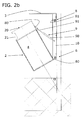
- FIG. 2b shows a waste container 2, which is pivoted by a pivot angle ⁇ from the filling position to the emptying position.
- a pivoting means 9 is attached to the support section 10 and the waste container 2, whereby a supported sprung and dampened pivoting of the waste container 2, together with the inner inner container 4 by a pivot angle ⁇ relative to the vertical can be reached.
- the waste collection device 1 according to the invention has a swivel angle ⁇ which is smaller than 90 °.
- the illustrated embodiment even has a swivel angle ⁇ less than 45 °, wherein the swivel range pivots the waste container 2 just until the lid 3, the upper discharge opening 20 releases a removal of the inner container is possible.
- the pivoting means 9 is formed here by an adjustable damping cylinder 9 as a pneumatic pivoting means, which includes a pressure tube 90 and a piston rod 91.
- the damping cylinder 9 is filled for example with oil and prevents uncontrolled pivoting of the waste container 2 about the pivot axis 5.
- the damping cylinder 9 allows by a suitable choice of the filling pressure, the adjustment of the tensile force of the piston rod 91, whereby the force on the weight of the waste container to be pivoted second can be adjusted. It is therefore adjustable to adjust the inertia of the waste container 2 during pivoting.
- the damping cylinder 9 provides a sprung and dampened pivotability of the waste container 2, with a small footprint, so that this damping mechanism is housed in the region of the holding profile 10 between the carrier 7 and the waste container 2 hidden and protected.
- a gas pressure spring 9 can be used as a hydropneumatic pivoting means 9 in a further embodiment.
- the adjustment of the filling pressure of such a gas spring 9 allows the variation of the pressure force that can be applied by the gas spring 9 for pivoting.
- the upper emptying opening 20 is pivoted by the lid 3 in such a way that the inner container 4 can be removed from the refuse container 2 approximately parallel to the longitudinal axis L.
- FIG. 3a shows a plan view of a lid 3, which is integrally formed or fixed to the support 7 on the support section 10, that the filling opening 21 is closed in position of the refuse container 2 in the filling position and no rainwater or other in the waste container 2 and the inner container 4 stored therein can penetrate.
- the fixed arrangement of the lid 3 serves to protect against vandalism.
- FIG. 3b shows a plan view of a waste collection device 1 with the omission of the lid. 3
- FIG. 3c shows a detailed representation of Verreigelungsvorraum 8, and the pivoting hinge 6.
- the two-piece locking device 8 can be seen in the foreground. Shown dashed is the lower pivot hinge 6, which has a hinge fork 60 integrally formed on the outer wall of the waste container 2 and a hinge pin 61.
- the hinge pin 61 traverses the diaphragm 10, which is U-shaped and the hinge fork 60, so that a pivoting movement about the pivot axis 5 can be achieved.
- the locking device 8 may include, for example, a locking lug 80 formed on the waste container 2, as well as a locking hook 81 operatively connected thereto on the holding device 7. With the key, the connection between the locking hook 81 and the locking eyelet 80 is releasable, so that an intended pivoting into the emptying position is possible. It is advantageous to form the locking device 8 such that an automatic locking is given during the pivoting into the filling position. In this case, the locking hook 81 snaps into the locking eyelet 80 as soon as the distance has fallen below a certain value.
- the inner container comprises a handle 40.
- the handle 40 is arranged in the region of the upper edge of the inner container 4 and formed on the inner wall of the inner container 4. With the dashed arrow, the removal direction is approximately parallel to the longitudinal axis L of the waste container 2 indicated.
- the handle 40 is not diametrically mounted over the opening of the inner container, but marginal, so that it can not be contaminated during filling as possible.
- this is preferably made of a light metal such as aluminum.
- the depth of the waste container 2 is made larger than the depth of the inner container 4. After emptying the inner container 4, this is again inserted into the waste container 2.
- FIG. 5 shows two opposing waste container 2, wherein the respective filling openings 21 are rotated by 180 ° to the carrier 7 are aligned.
- the waste containers 2 are each provided with a pivoting means 9, a pivoting hinge 6, and a locking device 8 and can be pivoted independently of each other and thus emptied.
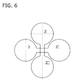
- FIG. 6 is a plan view of the lid 3 of a system comprising four waste containers 2, which are arranged on a holding device 9 in the form of a freestanding square post shown. The respectively in An angle of 90 ° to each other arranged waste container 2 are each independently filled and emptied.
- a carrier 7 may be a polygonal post or a mast, as in Figure 7a shown serve.
- a carrier 7 as a solid post 7 made of thick-walled square steel tube, hot-dip galvanized, powder-coated industrial and advantageously provided with an anti-graffiti color due to the vandalism security.
- the attachment of the waste container 2 and the holding profile 10 to the carrier 7 is in known ways, for example by means of steel strips as in Figure 7a shown or by wall fittings in the wall 7 according to FIG. 7b feasible.
Landscapes
- Engineering & Computer Science (AREA)
- Mechanical Engineering (AREA)
- Refuse Receptacles (AREA)
Abstract
Description
- Die vorliegende Erfindung beschreibt eine Abfallsammelvorrichtung befestigbar an einem Träger, mit einem, eine obere Entleerungsöffnung aufweisenden Abfallbehälter, wobei am Abfallbehälter ein Schwenkscharnier angeordnet ist, sodass der Abfallbehälter von einer Befüllposition in eine Entleerungsposition um eine, etwa senkrecht zu einer Längsachse verlaufende Schwenkachse um einen Schwenkwinkel verschwenkbar gelagert ist.
- Bekannte Abfallsammelvorrichtungen für den öffentlichen Raum zeichnen sich vor allem durch ihre Robustheit aus. Um eine möglichst lange Lebensdauer zu gewährleisten werden derartige Abfallsammelvorrichtungen aus Metallen, bevorzugt aus Stählen hergestellt, welche ausreichend korrosionsbeständig sein müssen, um Umwelteinflüssen trotzen zu können. Diese Abfallsammelvorrichtungen umfassen einen massiven Abfallbehälter welcher wahlweise mit einem Müllsack bestückt werden kann. Durch eine obere Öffnung des Abfallbehälters oder eine im Bereich einer Seitenwand des Abfallbehälters befindliche Befüllungsöffnung ist Abfall einbringbar.
- Bekannte Ausführungsformen solcher Abfallbehälter sind an einer Haltevorrichtung um eine Schwenkachse schwenkbar befestigt angeordnet, sodass der Abfallbehälter zur Entleerung aus einer Befüllposition in eine Entleerungsposition verschwenkbar ist. Die Schwenkbewegung wird durch die Lagerung des Abfallbehälters an einem Schwenkmittel, beispielsweise an einem Scharnier ermöglicht. In der Befüllposition steht der Abfallbehälter nahezu vertikal, sodass der Abfall durch die Schwerkraft im Abfallbehälter gehalten wird. In der Entleerungsposition ist der Abfallbehälter um mehr als 90° aus der nahezu vertikalen Befüllposition ausgelenkt und derart orientiert, das der gesammelte Abfall durch die obere Öffnung des Abfallbehälters nach unten austreten kann. Der Abfall wird durch ein Auffangbehältnis, beispielsweise von einem Sammelbehälter oder einem Müllsack nach der Verschwenkung des Abfallbehälters in die Entleerungsposition aufgenommen und abtransportiert.
- Aufgrund der unhandlichen, schweren und massiven Ausgestaltung des Abfallbehälters ist die Schwenkbewegung des Abfallbehälters in die Entleerungsposition und wieder zurück in die Befüllposition nur unter grossem Kraftaufwand der Person, welche den Abfallbehälter leert, möglich. Ein unkontrolliertes Umschwenken des Abfallbehälters von der Befüllposition in die Entleerungsposition kann neben dem ungewollten Entweichen von Abfall auch zu Verletzungen durch den massiven Abfallbehälter führen.
- Die vorliegende Erfindung hat sich zur Aufgabe gestellt eine Abfallsammelvorrichtung zu schaffen, die eine vereinfachte Entleerung des Abfallbehälters ohne grossen Kraftaufwand erlaubt.
- Ein bevorzugtes Ausführungsbeispiel des Erfindungsgegenstandes wird nachstehend im Zusammenhang mit den anliegenden Zeichnungen beschrieben.
- Figur 1
- zeigt eine frontale Ansicht auf eine Abfallsammelvorrichtung, während
- Figur 2a
- eine Seitenansicht der Abfallsammelvorrichtung mit teilweise geschnittenem Halteprofil in Befüllposition und
- Figur 2b
- eine Seitenansicht der verschwenkten Abfallsammelvorrichtung mit teilweise geschnittenem Halteprofil in Entleerungsposition zeigt.
- Figur 3a
- zeigt eine Aufsicht auf einen Deckel der Abfallsammelvorrichtung, während
- Figur 3b
- eine Aufsicht auf die Abfallsammelvorrichtung mit entferntem Deckel zeigt.
- Figur 3c
- zeigt den Bereich der Verriegelungsvorrichtung in einer Detailansicht gemäss
Figur 3b . - Figur 4
- zeigt eine perspektivische Ansicht der Abfallsammelvorrichtung mit in Entleerungsposition verschwenktem Abfallbehälter.
- Figur 5
- zeigt eine Gruppierung umfassend zwei Abfallsammelvorrichtungen an eine Träger in einer Seitenansicht mit teilweise entfernter Blende, während
- Figur 6
- eine Aufsicht auf die Deckel einer Vierergruppierung von Abfallsammelvorrichtungen an einem Träger befestigt zeigt.
- Figur 7a
- zeigt eine Seitenansicht einer Abfallsammelvorrichtung mit teilweise geschnittenem Halteprofil, wobei der Träger ein Mast ist, während
- Figur 7b
- eine Seitenansicht einer Abfallsammelvorrichtung an einer Wand als Träger zeigt.
- Mindestens eine erfindungsgemässe Abfallsammelvorrichtung 1 ist an einen Träger 7 schwenkbar gelagert und weist einen vertikal positionierten Abfallbehälter 2 in einer Befüllposition auf, wie in
Figur 1 in einer Seitenansicht gezeigt. Ein am Träger 7 fixierter Deckel 3 schliesst den Abfallbehälter 2 in der Befüllposition ab. Im Inneren des Abfallbehälters 2 ist ein Innenbehälter 4 angeordnet, welcher in der Ansicht schematisch dargestellt ist. - Der Innenbehälter 4 ist lösbar innerhalb des Abfallbehälters 2 gelagert, wobei die Seitenwände des Abfallbehälters 2 und des Innenbehälters 4 in etwa konzentrisch verlaufen und der Aussendurchmesser des Innenbehälters 4 geringfügig kleiner als der Innendurchmesser des Abfallbehälters 2 gewählt ist. Der Innenbehälter 4 ist in etwa parallel zur Längsachse L der Abfallsammelvorrichtung 1 angeordnet, wobei die Tiefe des Abfallbehälters 2 grösser als die Tiefe des Innebehälters 4 gewählt ist.
- Die Befüllung des Abfallbehälters 2 erfolgt durch eine, in der zylindrischen Mantelwand angeordnete Befüllungsöffnung 21, welche sich unterhalb der Oberkante des Abfallbehälters 2 und oberhalb der Oberkante des Innenbehälters 4 befindet und von einer Aussparung gebildet wird.
-
Figur 2a zeigt eine Seitenansicht der Abfallsammelvorrichtung 1, wobei ein, am Träger 7 angeformtes oder befestigtes Halteprofil 10 zum besseren Verständnis sichtseitig weggelassen worden ist. Der Abfallbehälter 2 ist mittels einem Schwenkscharnier 6 am Träger 7 befestigt. - Durch das Schwenkscharnier 6 verläuft eine virtuelle Schwenkachse 5, durch welche eine Schwenkbewegung des Abfallbehälters 2 von der Befüllposition in eine Entleerungsposition durchführbar ist.
- Um eine unbeabsichtigte Schwenkbewegung des Abfallbehälters 2 aus der Befüllposition auszuschliessen, ist eine Verriegelungsvorrichtung 8 zwischen Abfallbehälter 2 und Halteprofil 10 vorgesehen. Das Halteprofil 10 ist ein U-Profil, welches bevorzugterweise mit dem Deckle 3 fest verbunden ist und mit seiner offenen Seite zum Abfallbehälter 2 zeigt. Hierin lassen sich alle beweglichen Teile geschützt unterbringen, während in der Entleerposition das Halteprofil einsehbar ist (siehe
Fig. 4 ) und somit alle beweglichen Teile einfach unterhalten werden können. - Es sind Mittel vorgesehen, die Verriegelungsvorrichtung 8, beispielsweise durch einen Schlüssel zu entriegeln. Diese Sicherung soll eine Leerung durch nicht autorisierte Personen vermeiden. Die Verriegelungsvorrichtung 8 ist bevorzugt derart ausgestaltet, dass diese von mehreren Seiten, insbesondere von zwei gegenüberliegenden Seiten des Trägers 7 zugänglich ist und damit bequem entriegelbar ist.
-
Figur 2b zeigt einen Abfallbehälter 2, welcher um einen Schwenkwinkel α aus der Befüllposition in die Entleerungsposition geschwenkt ist. Ein Verschwenkmittel 9 ist am Halteprofil 10 und am Abfallbehälter 2 befestigt, wodurch eine unterstützte gefederte und gedämpfte Verschwenkung des Abfallbehälters 2, samt innenliegenden Innenbehälter 4 um einen Schwenkwinkel α relativ zur Vertikalen erreichbar ist. Die erfindungsgemässe Abfallsammelvorrichtung 1 weist einen Schwenkwinkel α auf, welcher kleiner als 90° ist. Die dargestellte Ausführungsform weist sogar einen Schwenkwinkel α kleiner als 45° auf, wobei der Schwenkbereich den Abfallbehälter 2 gerade soweit verschwenkt, bis der Deckel 3 die obere Entleerungsöffnung 20 freigibt un eine Entnahme des Innenbehälters möglich ist. - Das Verschwenkmittel 9 wird hier von einem einstellbaren Dämpfungszylinder 9 als pneumatisches Verschwenkmittel gebildet, welche ein Druckrohr 90 und eine Kolbenstange 91 umfasst. Der Dämpfungszylinder 9 ist beispielsweise mit Öl gefüllt und verhindert ein unkontrolliertes Verschwenken des Abfallbehälters 2 um die Schwenkachse 5. Der Dämpfungszylinder 9 gestattet durch eine geeignete Wahl des Fülldruckes die Einstellung der Zugkraft der Kolbenstange 91, womit die Kraft auf das Gewicht des zu verschwenkenden Abfallbehälters 2 eingestellt werden kann. Es ist also die Einstellung der Trägheit des Abfallbehälters 2 bei der Verschwenkung einstellbar. Der Dämpfungszylinder 9 schafft eine gefederte und gedämpfte Verschwenkbarkeit des Abfallbehälters 2, bei geringem Platzbedarf, sodass dieser Dämpfungsmechanismus im Bereich des Halteprofils 10 zwischen dem Träger 7 und dem Abfallbehälter 2 verdeckt und geschützt untergebracht ist. Je schwerer der Innenbehälter 4 beladen ist umso grösser ist der Schwenkwinkel α und umso leichter lässt sich dieser aus dem Abfallbehälter 2 entnehmen.
- Als Verschwenkmittel 9 ist in einer weiteren Ausführungsform eine Gasdruckfeder 9 als hydropneumatisches Verschwenkmittel 9 einsetzbar. Die Einstellung des Fülldruckes einer solchen Gasdruckfeder 9 erlaubt die Variation der Druckkraft, die von der Gasdruckfeder 9 zur Verschwenkung aufgebracht werden kann.
- Wenn der Abfallbehälter 2 in die Entleerungsposition verschwenkt ist, ist die obere Entleerungsöffnung 20 von dem Deckel 3 derart verschwenkt, dass der Innenbehälter 4 in etwa parallel zur Längsachse L aus dem Abfallbehälter 2 entnehmbar ist.
-
Figur 3a zeigt eine Aufsicht auf einen Deckel 3, welcher an den Träger 7 am Halteprofil 10 derart angeformt oder befestigt ist, dass die Befüllungsöffnung 21 bei Stellung des Abfallbehälters 2 in Befüllposition verschlossen ist und kein Regenwasser oder sonstiges in den Abfallbehälter 2 und den darin gelagerten Innenbehälter 4 eindringen kann. Die feste Anordnung des Deckels 3 dient dem Schutz gegen Vandalismus.Figur 3b zeigt eine Aufsicht auf eine Abfallsammelvorrichtung 1 unter Weglassung des Deckels 3. -
Figur 3c zeigt eine Detaildarstellung der Verreigelungsvorrichtung 8, sowie des Schwenkscharniers 6. Die zweiteilige Verriegelungsvorrichtung 8 ist im Vordergrund erkennbar. Gestrichelt dargestellt ist das tiefer liegende Schwenkscharnier 6, welches eine Scharniergabel 60 angeformt an der Aussenwand des Abfallbehälters 2 und einen Scharnierbolzen 61 aufweist. Der Scharnierbolzen 61 quert die Blende 10, welche U-förmig ausgestaltet ist und die Scharniergabel 60, sodass eine Schwenkbewegung um die Schwenkachse 5 erreichbar ist. - Die Verriegelungsvorrichtung 8 kann beispielsweise eine am Abfallbehälter 2 angeformte Verriegelungsöse 80, sowie einen damit wirkverbindbaren Verriegelungshaken 81 an der Haltevorrichtung 7 umfassen. Mit dem Schlüssel ist die Verbindung zwischen dem Verriegelungshaken 81 und der Verriegelungsöse 80 lösbar, sodass eine beabsichtigte Verschwenkung in die Entleerungsposition möglich wird. Es ist vorteilhaft die Verriegelungsvorrichtung 8 derart auszubilden, dass eine automatische Verriegelung bei der Verschwenkung in die Befüllposition gegeben ist. Dabei schnappt der Verriegelungshaken 81 entsprechend in die Verriegelungsöse 80 ein, sobald der Abstand einen bestimmten Wert unterschritten hat.
- Nach der Leerung des Innenbehälters 4, wird dieser wieder in den Abfallbehälter 2 eingebracht und der Abfallbehälter 2 samt Innenbehälter 4 zurück in die Befüllposition geschwenkt. Sobald der Verriegelungshaken 81 in die Verriegelungsöse 80 eingreift und die Verriegelungsvorrichtung 8 den Abfallbehälter 2 wieder fest in der Befüllposition hält, verbleibt der Abfallbehälter 2 in dieser Befüllposition. (Siehe
Fig. 3c ) - Um den Innenbehälter 4 einfach in Richtung der Längsachse L aus dem Abfallbehälter 2 zu entnehmen, umfasst der Innenbehälter einen Griff 40. In einer bevorzugten Ausführungsform gemäss
Figur 4 ist der Griff 40 im Bereich der Oberkante des Innenbehälters 4 angeordnet und an der Innenwand des Innenbehälters 4 angeformt. Mit dem gestrichelten Pfeil ist die Entnahmerichtung etwa parallel zur Längsachse L des Abfallbehälters 2 angedeutet. Der Griff 40 ist nicht diametral über der Öffnung des Innenbehälters angebracht, sondern randständig, damit dieser während des Befüllens möglichst nicht verschmutzt werden kann. - Zur Erleichterung der Entnahme des Innenbehälters 4 ist dieser bevorzugt aus einem Leichtmetall wie Aluminium hergestellt. Damit ein Befüllen durch die Befüllungsöffnung 21 möglich ist, ist die Tiefe des Abfallbehälters 2 grösser ausgeführt, als die Tiefe des Innenbehälters 4. Nach der Leerung des Innenbehälters 4 ist dieser wieder in den Abfallbehälter 2 einführbar.
- In den
Figuren 5 und6 sind Beispiele für die Anbringung einer Mehrzahl von Abfallbehältern 2 an einem Träger 7 gezeigt, welche eine Gruppierung von Abfallbehältern zur Aufnahme von Abfall bilden. -
Figur 5 zeigt zwei einander gegenüberliegende Abfallbehälter 2, wobei die jeweiligen Befüllungsöffnungen 21 um 180° verdreht zum Träger 7 ausgerichtet sind. Die Abfallbehälter 2 sind jeweils mit einem Verschwenkmittel 9, einem Schwenkscharnier 6, sowie einer Verriegelungsvorrichtung 8 versehen und können voneinander unabhängig verschwenkt und damit entleert werden. - In
Figur 6 ist eine Aufsicht auf die Deckel 3 eines Systems umfassend vier Abfallbehälter 2, welche an einer Haltevorrichtung 9 in Form eines freistehenden Vierkantpfostens angeordnet sind, gezeigt. Die jeweils in einem Winkel von 90° zueinander angeordneten Abfallbehälter 2 sind jeweils unabhängig voneinander befüll- und entleerbar. - Als Träger 7 kann ein Mehrkantpfosten oder ein Mast, wie in
Figur 7a gezeigt, dienen. Bevorzugt wird ein Träger 7 als massiver Pfosten 7 aus dickwandigem Vierkantstahlrohr, feuerverzinkt, industriell pulverbeschichtet und aufgrund der Vandalensicherheit vorteilhaft mit einer Antigraffiti-Farbe versehen, verwendet. - Ein Träger 7 in Form einer Gebäudewand oder einer freistehenden Wand, wie in
Figur 7b , ist aber ebenso wählbar. - Die Befestigung des Abfallbehälters 2 bzw. des Halteprofils 10 an dem Träger 7 ist auf bekannte Arten, beispielsweise mittels Stahlbändern wie in
Figur 7a gezeigt oder durch Wandverschraubungen in die Wand 7 gemässFigur 7b durchführbar. - Zur Erreichung einer stabilen vandalensicheren Konstruktion ist die Verwendung von Bauteilen aus Edelstahl für den Abfallbehälter 2, die Verriegelungsvorrichtung 8, das Verschwenkmittel 9 und das Halteprofil 10 vorteilhaft.
- Zum vereinfachten Entleeren des Innenbehälters 4, wird dieser aus Leichtmetall, wie Aluminium gefertigt. Da dieser Innenbehälter nur autorisierten Personen zugänglich ist, ist die Wahl von Aluminium ohne Probleme möglich.
-
- 1
- Abfallsammelvorrichtung
- 2
- Abfallbehälter
20 obere Entleerungsöffnung
21 Befüllungsöffnung - 3
- Deckel
- 4
- Innenbehälter
40 Griff - 5
- Schwenkachse
- 6
- Schwenkscharnier (Gelenk oder Scharnier)
60 Scharniergabel
61 Scharnierbolzen - 7
- Träger
- 8
- Verriegelungsvorrichtung
80 Verriegelungsöse
81 Verriegelungshaken - 9
- Verschwenkmittel (einstellbarer Dämpfungszylinder / Gasdruckfeder)
90 Druckrohr
91 Kolbenstange - 10
- Halteprofil
L Längsachse
α Schwenkwinkel
Claims (12)
- Abfallsammelvorrichtung (1) befestigbar an einem Träger (7), mit einem,
eine obere Entleerungsöffnung (20) aufweisenden Abfallbehälter (2),
wobei am Abfallbehälter (2) ein Schwenkscharnier (6) angeordnet ist, sodass der Abfallbehälter (2) von einer Befüllposition in eine Entleerungsposition um eine, etwa senkrecht zu einer Längsachse (L) verlaufende Schwenkachse (5) um einen Schwenkwinkel (α) verschwenkbar gelagert ist, dadurch gekennzeichnet, dass
am Abfallbehälter (2) ein Halteprofil (10) als U-Profil über das Schwenkscharnier (6) gelenkig verbunden ist und darin die beweglichen Teile, nämlich Schwenkscharnier (6), Verschwenkmittel (9) und Verriegelungsvorrichtung (8) untergebracht sind. - Abfallsammelvorrichtung (1) nach Anspruch 1, dadurch gekennzeichnet, dass das Verschwenkmittel (9) ein einstellbarer Dämpfungszylinder (9) ist, welcher zwischen Abfallbehälter (2) und Träger (7) am Halteprofil (10) verschwenkbar befestigt ist.
- Abfallsammelvorrichtung (1) nach Anspruch 2, dadurch gekennzeichnet, dass der einstellbare Dämpfungszylinder (9) ein Druckrohr (90) und eine Kolbenstange (91) aufweist und die Kraft in Ausschubrichtung der Kolbenstange (91) des Dämpfungszylinders (9) durch die Wahl des Fülldruckes des Öls innerhalb des Druckrohres (90) auf das Gewicht des Abfallbehälters (2) anpassbar ist.
- Abfallsammelvorrichtung (1) nach Anspruch 1, dadurch gekennzeichnet, dass das Verschwenkmittel (9) eine Gasdruckfeder (9) ist, welche zwischen Abfallbehälter (2) und Träger (7) am Halteprofil (10) verschwenkbar befestigt ist.
- Abfallsammelvorrichtung (1) nach Anspruch 1, dadurch gekennzeichnet, dass das Schwenkscharnier (6) und das Verschwenkmittel (9) ein gedämpftes Verschwenken des Abfallbehälters (2) von der Befüllposition in die Entleerungsposition um den Schwenkwinkel (α) kleiner 90° relativ zur Vertikalen erlaubt.
- Abfallsammelvorrichtung nach Anspruch 1, dadurch gekennzeichnet, dass ein Deckel (3) am Halteprofil (10) und/oder am Träger (7) derart angeformt oder befestigt ist, dass der Abfallbehälter (2) in der Befüllposition durch den Deckel (3) verschlossen ist.
- Abfallsammelvorrichtung nach Anspruch 1, dadurch gekennzeichnet, dass eine Verriegelungsvorrichtung (8) den Abfallbehälter (2) in der Befüllposition fixiert.
- Abfallsammelvorrichtung nach Anspruch 1, dadurch gekennzeichnet, dass die Tiefe des Abfallbehälters (2) grösser als die Tiefe des Innenbehälters (4) ist.
- Abfallsammelvorrichtung nach Anspruch 8, dadurch gekennzeichnet, dass eine Befüllungsöffnung (21) in der Mantelwand des Abfallbehälters (2) unterhalb der Oberkante des Abfallbehälters und oberhalb der Oberkante des Innenbehälters (4) ausgespart ist.
- Abfallsammelvorrichtung nach Anspruch 1, dadurch gekennzeichnet, dass am Innenbehälter (4) im Bereich der Oberkante des Innenbehälters (4) ein Griff (40) zur Entnahme des Innenbehälters (4) aus dem Abfallbehälter (2) angeordnet ist.
- Abfallsammelvorrichtung nach Anspruch 9, dadurch gekennzeichnet, dass der Griff (40) an der Innenwand des Innenbehälters (4) angeformt ist.
- Gruppierung von Abfallsammelvorrichtungen zur Aufnahme und Sammlung von Abfall,
dadurch gekennzeichnet, dass eine Mehrzahl von Abfallsammelvorrichtungen (1) gemäss Anspruch 1 mit je einem Halteprofil (10) an einem Träger (7) befestigt angeordnet ist.
Applications Claiming Priority (1)
| Application Number | Priority Date | Filing Date | Title |
|---|---|---|---|
| CH1622009A CH700368A2 (de) | 2009-02-05 | 2009-02-05 | Abfallsammelvorrichtung. |
Publications (2)
| Publication Number | Publication Date |
|---|---|
| EP2216272A1 true EP2216272A1 (de) | 2010-08-11 |
| EP2216272B1 EP2216272B1 (de) | 2016-10-12 |
Family
ID=42077813
Family Applications (1)
| Application Number | Title | Priority Date | Filing Date |
|---|---|---|---|
| EP10151666.4A Active EP2216272B1 (de) | 2009-02-05 | 2010-01-26 | Abfallsammelvorrichtung |
Country Status (2)
| Country | Link |
|---|---|
| EP (1) | EP2216272B1 (de) |
| CH (1) | CH700368A2 (de) |
Cited By (1)
| Publication number | Priority date | Publication date | Assignee | Title |
|---|---|---|---|---|
| DE102017111231A1 (de) | 2017-05-23 | 2018-11-29 | Man Truck & Bus Ag | Behältersystem für ein Kraftfahrzeug |
Citations (4)
| Publication number | Priority date | Publication date | Assignee | Title |
|---|---|---|---|---|
| EP0060794A2 (de) * | 1981-03-17 | 1982-09-22 | COMPAGNIE PLASTIC OMNIUM Société Anonyme dite: | Papierkorb |
| DE8807167U1 (de) * | 1988-06-01 | 1988-07-14 | Beck Industrieformen + Bauelemente GmbH, 73760 Ostfildern | Abfallbehälter |
| DE29512488U1 (de) * | 1995-08-03 | 1996-01-25 | Peltsarszky, Peter, 42285 Wuppertal | Behältersystem zur Mülltrennung insbesondere zur Verwendung im privaten und öffentlichen Bereich |
| DE19740675A1 (de) * | 1997-09-16 | 1999-03-18 | Otto Geb Kg | Abfallbehälter |
-
2009
- 2009-02-05 CH CH1622009A patent/CH700368A2/de not_active Application Discontinuation
-
2010
- 2010-01-26 EP EP10151666.4A patent/EP2216272B1/de active Active
Patent Citations (4)
| Publication number | Priority date | Publication date | Assignee | Title |
|---|---|---|---|---|
| EP0060794A2 (de) * | 1981-03-17 | 1982-09-22 | COMPAGNIE PLASTIC OMNIUM Société Anonyme dite: | Papierkorb |
| DE8807167U1 (de) * | 1988-06-01 | 1988-07-14 | Beck Industrieformen + Bauelemente GmbH, 73760 Ostfildern | Abfallbehälter |
| DE29512488U1 (de) * | 1995-08-03 | 1996-01-25 | Peltsarszky, Peter, 42285 Wuppertal | Behältersystem zur Mülltrennung insbesondere zur Verwendung im privaten und öffentlichen Bereich |
| DE19740675A1 (de) * | 1997-09-16 | 1999-03-18 | Otto Geb Kg | Abfallbehälter |
Cited By (1)
| Publication number | Priority date | Publication date | Assignee | Title |
|---|---|---|---|---|
| DE102017111231A1 (de) | 2017-05-23 | 2018-11-29 | Man Truck & Bus Ag | Behältersystem für ein Kraftfahrzeug |
Also Published As
| Publication number | Publication date |
|---|---|
| CH700368A2 (de) | 2010-08-13 |
| EP2216272B1 (de) | 2016-10-12 |
Similar Documents
| Publication | Publication Date | Title |
|---|---|---|
| DE69811754T2 (de) | Verriegelungsvorrichtung für einen Behälterdeckel und damit ausgerüsteter Behälter | |
| EP4001171B1 (de) | Mülltonne mit einer schlossvorrichtung | |
| EP2216272B1 (de) | Abfallsammelvorrichtung | |
| DE19708193A1 (de) | Müll- oder ähnlicher über Kopf zu entleerender Behälter | |
| DE69809328T2 (de) | Vorrichtung zum unterirdischen Sammeln von Müll | |
| DE102013201012B4 (de) | Behältnis zum Aufbewahren von Boldmunition auf einem Schiff | |
| DE3029982A1 (de) | Sammelbehaelter, insbesondere fuer altglas | |
| DE4209069A1 (de) | Schachtabdeckung | |
| DE102010017955A1 (de) | Verriegelungsvorrichtung für einen Müllbehälter und Müllbehälter | |
| DE2709836A1 (de) | Muellbehaelter-schrank mit drehscheibe | |
| DE4216991C2 (de) | Tragbarer Mülleimer | |
| DE202017102440U1 (de) | Vorrichtung zur Aufnahme von Gefahrstoffen | |
| DE4103686C1 (en) | Waste container with good stability - includes device for attachment to walls and can accommodate an inner container e.g. wire basket | |
| DE9209862U1 (de) | Vorrichtung zum vorzugsweise getrennten Sammeln von Abfall | |
| DE202015103194U1 (de) | Reingungsvorrichtung für einen Schachteinsatz | |
| EP3945042A1 (de) | Müllcontainer | |
| DE29512609U1 (de) | Müllbehälter mit angelenktem Verschlußdeckel | |
| EP0819623B1 (de) | Vorrichtung zum Entleeren von Müllgrossbehältern | |
| DE202008000530U1 (de) | Vorrichtung zum Handhaben eines Fasses | |
| DE3935152C2 (de) | ||
| DE10053637C2 (de) | Frontumleerbehälter mit am Behälterkorpus angeordneten verriegel-und schwenkbaren Zwischenrahmen | |
| DE102023112473A1 (de) | Aufnahmebehälter | |
| DE1931163A1 (de) | Vorrichtung zur Aufnahme von Muelltonnen | |
| DE151107C (de) | ||
| DE10031448B4 (de) | Tresenmodul mit Haube |
Legal Events
| Date | Code | Title | Description |
|---|---|---|---|
| PUAI | Public reference made under article 153(3) epc to a published international application that has entered the european phase |
Free format text: ORIGINAL CODE: 0009012 |
|
| AK | Designated contracting states |
Kind code of ref document: A1 Designated state(s): AT BE BG CH CY CZ DE DK EE ES FI FR GB GR HR HU IE IS IT LI LT LU LV MC MK MT NL NO PL PT RO SE SI SK SM TR |
|
| 17P | Request for examination filed |
Effective date: 20110204 |
|
| 17Q | First examination report despatched |
Effective date: 20110503 |
|
| GRAP | Despatch of communication of intention to grant a patent |
Free format text: ORIGINAL CODE: EPIDOSNIGR1 |
|
| INTG | Intention to grant announced |
Effective date: 20160531 |
|
| GRAS | Grant fee paid |
Free format text: ORIGINAL CODE: EPIDOSNIGR3 |
|
| GRAA | (expected) grant |
Free format text: ORIGINAL CODE: 0009210 |
|
| AK | Designated contracting states |
Kind code of ref document: B1 Designated state(s): AT BE BG CH CY CZ DE DK EE ES FI FR GB GR HR HU IE IS IT LI LT LU LV MC MK MT NL NO PL PT RO SE SI SK SM TR |
|
| REG | Reference to a national code |
Ref country code: GB Ref legal event code: FG4D Free format text: NOT ENGLISH |
|
| REG | Reference to a national code |
Ref country code: CH Ref legal event code: EP |
|
| REG | Reference to a national code |
Ref country code: AT Ref legal event code: REF Ref document number: 836287 Country of ref document: AT Kind code of ref document: T Effective date: 20161015 |
|
| REG | Reference to a national code |
Ref country code: CH Ref legal event code: NV Representative=s name: SCHNEIDER FELDMANN AG PATENT- UND MARKENANWAEL, CH |
|
| REG | Reference to a national code |
Ref country code: IE Ref legal event code: FG4D Free format text: LANGUAGE OF EP DOCUMENT: GERMAN |
|
| REG | Reference to a national code |
Ref country code: DE Ref legal event code: R096 Ref document number: 502010012538 Country of ref document: DE |
|
| REG | Reference to a national code |
Ref country code: LT Ref legal event code: MG4D |
|
| REG | Reference to a national code |
Ref country code: NL Ref legal event code: MP Effective date: 20161012 |
|
| PG25 | Lapsed in a contracting state [announced via postgrant information from national office to epo] |
Ref country code: LV Free format text: LAPSE BECAUSE OF FAILURE TO SUBMIT A TRANSLATION OF THE DESCRIPTION OR TO PAY THE FEE WITHIN THE PRESCRIBED TIME-LIMIT Effective date: 20161012 |
|
| PG25 | Lapsed in a contracting state [announced via postgrant information from national office to epo] |
Ref country code: GR Free format text: LAPSE BECAUSE OF FAILURE TO SUBMIT A TRANSLATION OF THE DESCRIPTION OR TO PAY THE FEE WITHIN THE PRESCRIBED TIME-LIMIT Effective date: 20170113 Ref country code: LT Free format text: LAPSE BECAUSE OF FAILURE TO SUBMIT A TRANSLATION OF THE DESCRIPTION OR TO PAY THE FEE WITHIN THE PRESCRIBED TIME-LIMIT Effective date: 20161012 Ref country code: NO Free format text: LAPSE BECAUSE OF FAILURE TO SUBMIT A TRANSLATION OF THE DESCRIPTION OR TO PAY THE FEE WITHIN THE PRESCRIBED TIME-LIMIT Effective date: 20170112 Ref country code: SE Free format text: LAPSE BECAUSE OF FAILURE TO SUBMIT A TRANSLATION OF THE DESCRIPTION OR TO PAY THE FEE WITHIN THE PRESCRIBED TIME-LIMIT Effective date: 20161012 |
|
| PGFP | Annual fee paid to national office [announced via postgrant information from national office to epo] |
Ref country code: DE Payment date: 20170117 Year of fee payment: 8 |
|
| PG25 | Lapsed in a contracting state [announced via postgrant information from national office to epo] |
Ref country code: FI Free format text: LAPSE BECAUSE OF FAILURE TO SUBMIT A TRANSLATION OF THE DESCRIPTION OR TO PAY THE FEE WITHIN THE PRESCRIBED TIME-LIMIT Effective date: 20161012 Ref country code: ES Free format text: LAPSE BECAUSE OF FAILURE TO SUBMIT A TRANSLATION OF THE DESCRIPTION OR TO PAY THE FEE WITHIN THE PRESCRIBED TIME-LIMIT Effective date: 20161012 Ref country code: BE Free format text: LAPSE BECAUSE OF NON-PAYMENT OF DUE FEES Effective date: 20170131 Ref country code: NL Free format text: LAPSE BECAUSE OF FAILURE TO SUBMIT A TRANSLATION OF THE DESCRIPTION OR TO PAY THE FEE WITHIN THE PRESCRIBED TIME-LIMIT Effective date: 20161012 Ref country code: PL Free format text: LAPSE BECAUSE OF FAILURE TO SUBMIT A TRANSLATION OF THE DESCRIPTION OR TO PAY THE FEE WITHIN THE PRESCRIBED TIME-LIMIT Effective date: 20161012 Ref country code: PT Free format text: LAPSE BECAUSE OF FAILURE TO SUBMIT A TRANSLATION OF THE DESCRIPTION OR TO PAY THE FEE WITHIN THE PRESCRIBED TIME-LIMIT Effective date: 20170213 Ref country code: IS Free format text: LAPSE BECAUSE OF FAILURE TO SUBMIT A TRANSLATION OF THE DESCRIPTION OR TO PAY THE FEE WITHIN THE PRESCRIBED TIME-LIMIT Effective date: 20170212 Ref country code: HR Free format text: LAPSE BECAUSE OF FAILURE TO SUBMIT A TRANSLATION OF THE DESCRIPTION OR TO PAY THE FEE WITHIN THE PRESCRIBED TIME-LIMIT Effective date: 20161012 |
|
| PGFP | Annual fee paid to national office [announced via postgrant information from national office to epo] |
Ref country code: AT Payment date: 20161223 Year of fee payment: 8 |
|
| REG | Reference to a national code |
Ref country code: DE Ref legal event code: R097 Ref document number: 502010012538 Country of ref document: DE |
|
| PG25 | Lapsed in a contracting state [announced via postgrant information from national office to epo] |
Ref country code: RO Free format text: LAPSE BECAUSE OF FAILURE TO SUBMIT A TRANSLATION OF THE DESCRIPTION OR TO PAY THE FEE WITHIN THE PRESCRIBED TIME-LIMIT Effective date: 20161012 Ref country code: SK Free format text: LAPSE BECAUSE OF FAILURE TO SUBMIT A TRANSLATION OF THE DESCRIPTION OR TO PAY THE FEE WITHIN THE PRESCRIBED TIME-LIMIT Effective date: 20161012 Ref country code: DK Free format text: LAPSE BECAUSE OF FAILURE TO SUBMIT A TRANSLATION OF THE DESCRIPTION OR TO PAY THE FEE WITHIN THE PRESCRIBED TIME-LIMIT Effective date: 20161012 Ref country code: CZ Free format text: LAPSE BECAUSE OF FAILURE TO SUBMIT A TRANSLATION OF THE DESCRIPTION OR TO PAY THE FEE WITHIN THE PRESCRIBED TIME-LIMIT Effective date: 20161012 Ref country code: EE Free format text: LAPSE BECAUSE OF FAILURE TO SUBMIT A TRANSLATION OF THE DESCRIPTION OR TO PAY THE FEE WITHIN THE PRESCRIBED TIME-LIMIT Effective date: 20161012 |
|
| PLBE | No opposition filed within time limit |
Free format text: ORIGINAL CODE: 0009261 |
|
| STAA | Information on the status of an ep patent application or granted ep patent |
Free format text: STATUS: NO OPPOSITION FILED WITHIN TIME LIMIT |
|
| PG25 | Lapsed in a contracting state [announced via postgrant information from national office to epo] |
Ref country code: BG Free format text: LAPSE BECAUSE OF FAILURE TO SUBMIT A TRANSLATION OF THE DESCRIPTION OR TO PAY THE FEE WITHIN THE PRESCRIBED TIME-LIMIT Effective date: 20170112 Ref country code: IT Free format text: LAPSE BECAUSE OF FAILURE TO SUBMIT A TRANSLATION OF THE DESCRIPTION OR TO PAY THE FEE WITHIN THE PRESCRIBED TIME-LIMIT Effective date: 20161012 Ref country code: SM Free format text: LAPSE BECAUSE OF FAILURE TO SUBMIT A TRANSLATION OF THE DESCRIPTION OR TO PAY THE FEE WITHIN THE PRESCRIBED TIME-LIMIT Effective date: 20161012 |
|
| 26N | No opposition filed |
Effective date: 20170713 |
|
| PG25 | Lapsed in a contracting state [announced via postgrant information from national office to epo] |
Ref country code: MC Free format text: LAPSE BECAUSE OF FAILURE TO SUBMIT A TRANSLATION OF THE DESCRIPTION OR TO PAY THE FEE WITHIN THE PRESCRIBED TIME-LIMIT Effective date: 20161012 |
|
| REG | Reference to a national code |
Ref country code: FR Ref legal event code: ST Effective date: 20170929 |
|
| PG25 | Lapsed in a contracting state [announced via postgrant information from national office to epo] |
Ref country code: FR Free format text: LAPSE BECAUSE OF NON-PAYMENT OF DUE FEES Effective date: 20170131 |
|
| REG | Reference to a national code |
Ref country code: IE Ref legal event code: MM4A |
|
| PG25 | Lapsed in a contracting state [announced via postgrant information from national office to epo] |
Ref country code: SI Free format text: LAPSE BECAUSE OF FAILURE TO SUBMIT A TRANSLATION OF THE DESCRIPTION OR TO PAY THE FEE WITHIN THE PRESCRIBED TIME-LIMIT Effective date: 20161012 Ref country code: LU Free format text: LAPSE BECAUSE OF NON-PAYMENT OF DUE FEES Effective date: 20170126 |
|
| REG | Reference to a national code |
Ref country code: BE Ref legal event code: MM Effective date: 20170131 |
|
| PG25 | Lapsed in a contracting state [announced via postgrant information from national office to epo] |
Ref country code: IE Free format text: LAPSE BECAUSE OF NON-PAYMENT OF DUE FEES Effective date: 20170126 |
|
| REG | Reference to a national code |
Ref country code: DE Ref legal event code: R119 Ref document number: 502010012538 Country of ref document: DE |
|
| REG | Reference to a national code |
Ref country code: AT Ref legal event code: MM01 Ref document number: 836287 Country of ref document: AT Kind code of ref document: T Effective date: 20180126 |
|
| PG25 | Lapsed in a contracting state [announced via postgrant information from national office to epo] |
Ref country code: MT Free format text: LAPSE BECAUSE OF FAILURE TO SUBMIT A TRANSLATION OF THE DESCRIPTION OR TO PAY THE FEE WITHIN THE PRESCRIBED TIME-LIMIT Effective date: 20161012 |
|
| PG25 | Lapsed in a contracting state [announced via postgrant information from national office to epo] |
Ref country code: DE Free format text: LAPSE BECAUSE OF NON-PAYMENT OF DUE FEES Effective date: 20180801 |
|
| PG25 | Lapsed in a contracting state [announced via postgrant information from national office to epo] |
Ref country code: AT Free format text: LAPSE BECAUSE OF NON-PAYMENT OF DUE FEES Effective date: 20180126 |
|
| PGFP | Annual fee paid to national office [announced via postgrant information from national office to epo] |
Ref country code: GB Payment date: 20190123 Year of fee payment: 10 |
|
| PG25 | Lapsed in a contracting state [announced via postgrant information from national office to epo] |
Ref country code: HU Free format text: LAPSE BECAUSE OF FAILURE TO SUBMIT A TRANSLATION OF THE DESCRIPTION OR TO PAY THE FEE WITHIN THE PRESCRIBED TIME-LIMIT; INVALID AB INITIO Effective date: 20100126 |
|
| PG25 | Lapsed in a contracting state [announced via postgrant information from national office to epo] |
Ref country code: CY Free format text: LAPSE BECAUSE OF NON-PAYMENT OF DUE FEES Effective date: 20161012 |
|
| PG25 | Lapsed in a contracting state [announced via postgrant information from national office to epo] |
Ref country code: MK Free format text: LAPSE BECAUSE OF FAILURE TO SUBMIT A TRANSLATION OF THE DESCRIPTION OR TO PAY THE FEE WITHIN THE PRESCRIBED TIME-LIMIT Effective date: 20161012 |
|
| PG25 | Lapsed in a contracting state [announced via postgrant information from national office to epo] |
Ref country code: TR Free format text: LAPSE BECAUSE OF FAILURE TO SUBMIT A TRANSLATION OF THE DESCRIPTION OR TO PAY THE FEE WITHIN THE PRESCRIBED TIME-LIMIT Effective date: 20161012 |
|
| GBPC | Gb: european patent ceased through non-payment of renewal fee |
Effective date: 20200126 |
|
| REG | Reference to a national code |
Ref country code: CH Ref legal event code: PFA Owner name: BURRI PUBLIC ELEMENTS AG, CH Free format text: FORMER OWNER: BURRI PUBLIC ELEMENTS AG, CH |
|
| PG25 | Lapsed in a contracting state [announced via postgrant information from national office to epo] |
Ref country code: GB Free format text: LAPSE BECAUSE OF NON-PAYMENT OF DUE FEES Effective date: 20200126 |
|
| PGFP | Annual fee paid to national office [announced via postgrant information from national office to epo] |
Ref country code: CH Payment date: 20250201 Year of fee payment: 16 |
|
| REG | Reference to a national code |
Ref country code: CH Ref legal event code: U11 Free format text: ST27 STATUS EVENT CODE: U-0-0-U10-U11 (AS PROVIDED BY THE NATIONAL OFFICE) Effective date: 20260201 |